Table of Contents
Advertisement
SVM170-A
RETURN TO MAIN MENU
October, 2006
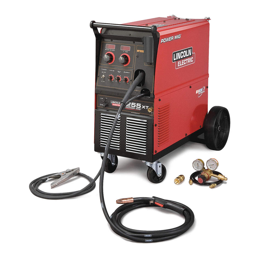
POWER MIG 255C
For use with machines having Code Number : 11192, 11218
Safety Depends on You
Lincoln arc welding and cutting
equipment is designed and built
with safety in mind. However,
your overall safety can be
increased by proper installation
. . . and thoughtful operation on
your part. DO NOT INSTALL,
OPERATE OR REPAIR THIS
EQUIPMENT WITHOUT READ-
ING THIS MANUAL AND THE
SAFETY PRECAUTIONS CON-
TAINED THROUGHOUT. And,
most importantly, think before
you act and be careful.
SERVICE MANUAL
Copyright © 2006 Lincoln Global Inc.
• World's Leader in Welding and Cutting Products •
• Sales and Service through Subsidiaries and Distributors Worldwide •
Cleveland, Ohio 44117-1199 U.S.A. TEL: 216.481.8100 FAX: 216.486.1751 WEB SITE: www.lincolnelectric.com
Advertisement
Chapters
Table of Contents
Troubleshooting

Related Manuals for Lincoln Electric POWER MIG SVM170-A


Summary of Contents for Lincoln Electric POWER MIG SVM170-A
-
Page 1: Service Manual
SVM170-A RETURN TO MAIN MENU October, 2006 POWER MIG 255C For use with machines having Code Number : 11192, 11218 Safety Depends on You Lincoln arc welding and cutting equipment is designed and built with safety in mind. However, your overall safety can be increased by proper installation . - Page 2 Miami, Florida 33135 or CSA Standard W117.2-1974. A Free copy of “Arc Welding Safety” booklet E205 is available from the Lincoln Electric Company, 22801 St. Clair Avenue, Cleveland, Ohio 44117-1199. BE SURE THAT ALL INSTALLATION, OPERATION, MAINTENANCE AND REPAIR PROCEDURES ARE PERFORMED ONLY BY QUALIFIED INDIVIDUALS.
-
Page 3: Electric Shock Can Kill
ELECTRIC SHOCK can kill. 3.a. The electrode and work (or ground) circuits are electrically “hot” when the welder is on. Do not touch these “hot” parts with your bare skin or wet clothing. Wear dry, hole-free gloves to insulate hands. 3.b. - Page 4 WELDING SPARKS can cause fire or explosion. 6.a. Remove fire hazards from the welding area. If this is not possible, cover them to prevent the welding sparks from starting a fire. Remember that welding sparks and hot materials from welding can easily go through small cracks and openings to adjacent areas.
- Page 5 PRÉCAUTIONS DE SÛRETÉ Pour votre propre protection lire et observer toutes les instructions et les précautions de sûreté specifiques qui parraissent dans ce manuel aussi bien que les précautions de sûreté générales suiv- antes: Sûreté Pour Soudage A L’Arc 1. Protegez-vous contre la secousse électrique: a.
- Page 6 RETURN TO MAIN MENU MASTER TABLE OF CONTENTS FOR ALL SECTIONS Page Safety ........... . . i-iv Installation .
-
Page 7: Table Of Contents
SECTION A Installation ............... Section A Technical Specifications —... -
Page 8: Installation
TECHNICAL SPECIFICATIONS – POWER MIG 255C Standard Voltage/Frequency Input Current @ 200 Amp Rated Output Input Current @ 250 Amp Rated Output 208/230/60 Hz 230/460/575/60 Hz Duty Cycle 100% Welding Current Range (Continuous) 30 – 300 Amps RECOMMENDED INPUT WIRE AND FUSE SIZES Input Voltage/ Fuse or Breaker Frequency (Hz) -
Page 9: Safety Precautions
Read entire installation section before starting installation. SAFETY PRECAUTIONS WARNING ELECTRIC SHOCK can kill. • Only qualified personnel should perform this installation. • Only personnel that have read and under- stood the POWER MIG 255C Operating Manual should install and operate this equip- ment. -
Page 10: Dual Voltage Machine Input Connections
FIGURE A.1 — DUAL VOLTAGE MACHINE INPUT CONNECTIONS. 3. The 208/230 volt 60 Hz model POWER MIG is shipped with a 10 ft. input cable and plug con- nected to the welder. A matching receptacle is supplied with the machine. Mount the receptacle in a suitable location using the screws provided. -
Page 11: Triple Voltage Machine Input Connections
FIGURE A.2 — TRIPLE VOLTAGE MACHINE INPUT CONNECTIONS. FIGURE A.3 — RECEPTACLE DIAGRAM. CONNECT TO A SYSTEM GROUNDING WIRE. SEE THE UNITED STATES NATIONAL ELECTRICAL CODE AND/OR LOCAL CODES FOR OTHER DETAILS AND MEANS FOR PROPER GROUNDING. CONNECT TO HOT WIRES OF A THREE-WIRE, SINGLE PHASE SYSTEM OR TO ONE PHASE OF A TWO OR... -
Page 12: Gun And Cable Installation
GUN AND CABLE INSTALLATION The Magnum 250L gun and cable provided with the POWER MIG 255C is factory installed with a liner for 0.035-0.045 in. (0.9-1.2 mm) electrode and an 0.035 in. (0.9 mm) contact tip. Install the 0.045 tip (also pro- vided) if this wire size is being used. - Page 13 SECTION B Operation ............... . Section B Product Description .
-
Page 14: Operation
Read entire Operation section before operating the POWER MIG 255C. Observe all safety information throughout this manual. OPERATION WARNING ELECTRIC SHOCK can kill. • Do not touch electrically live parts or electrode with skin or wet clothing. Insulate yourself from work and ground. -
Page 15: Product Description
A simple control scheme, consisting of continuous full range voltage and wire feed speed controls, provides versatility with ease of use and accuracy. -
Page 16: Description Of Controls
DESCRIPTION OF CONTROLS Power ON/OFF Switch — Place the lever in the "ON" position to energize the POWER MIG 255C. When the power is on, the red LED display lights illuminate. Voltage Control — This is a continuous control that gives full range adjustment of power source output voltage. -
Page 17: Procedure For Changing Drive And Idle Roll Sets
PROCEDURE FOR CHANGING DRIVE AND IDLE ROLL SETS 1. Turn off the power source. 2. Release the pressure on the idle roll by swinging the adjustable pressure arm down toward the back of the machine. Lift the cast idle roll assembly and allow it to sit in an upright position. -
Page 18: To Start The Welder
TO START THE WELDER Turn the Power Switch switch to ON. This lights the red LED display lights. With the desired voltage and wire speed selected, operate the gun trigger for welder out- put and to energize the wire feed motor. FEEDING WIRE ELECTRODE WARNING When triggering, the electrode and drive mecha-... - Page 19 5. Loosen the socket head cap screw that holds the connector bar against the gun bushing. Important: Do not attempt to completely remove the socket head cap screw. 6. Remove the outer wire guide, and push the gun bushing out of the wire drive. Because of the pre- cision fit, light tapping may be required to remove the gun bushing.
-
Page 20: Setting Run-In Speed On Standard Power Mig Feeder
SETTING RUN-IN SPEED ON STAN- DARD POWER MIG FEEDER FAST OR SLOW RUN-IN MODE SELECTION, (When Timer Option is not installed) The POWER MIG 255C is factory set for fast run-in mode where the wire feed will accelerate directly to the preset wire feed speed when the gun trigger is closed. -
Page 21: Avoiding Wire Feeding Problems
WARNING When using an open arc process, it is necessary to use correct eye, head, and body protection. 8. Position electrode over joint. End of electrode may be lightly touching the work. 9. Lower welding helmet, close gun trigger, and begin welding. -
Page 22: Welding Thermal Overload Protection
B-10 WELDING THERMAL OVERLOAD PROTECTION The POWER MIG 255C has built-in protective thermostats that respond to excessive temperature. They open the wire feed and welder output circuits if the machine exceeds the maximum safe operating temperature because of a frequent overload, or high ambient temperature plus overload. - Page 23 SECTION C Accessories ..............Section C Drive Roll Kits .
-
Page 24: Drive Roll Kits
DRIVE ROLL KITS Refer to Table C.1 for various drive roll kits that are available for the POWER MIG. All items in Bold are supplied standard with the POWER MIG. TABLE C.1 — AVAILABLE DRIVE ROLL KITS. Electrode Type Wire Size Solid Steel .023”-.030”... - Page 25 OPERATING INSTRUCTIONS FOR TIMER If the optional Timer Kit (K1701-1) is installed, select the desired mode with the selector switch: A. Normal Welding mode provides weld power only while the trigger switch is depressed. This is the same operation as when the Timer Kit is not installed.
- Page 26 MAKING A WELD WITH THE PRINCE XL SPOOL GUN The POWER MIG control circuitry is designed to sense either the spool gun or (built in) wire feeder trigger circuitry. The spool gun can easily be plugged in and will be ready to use. CAUTION Closing either gun trigger will cause the electrode of both guns to be electrically "HOT".
- Page 27 CAUTION Closing either gun trigger will cause the electrode of both guns to be electrically "HOT". Be sure unused gun is positioned so electrode or tip will not contact metal case or other metal common to work. ----------------------------------------------------------------------------- 1. Pulling the trigger for the built-in feeder gun: a.
- Page 28 NOTES POWER MIG 255...
- Page 29 SECTION D Maintenance ..............Section D Safety Precautions .
- Page 30 SAFETY PRECAUTIONS WARNING • Have a qualified electrician do the maintenance and troubleshooting work. • Disconnect the input power off using the disconnect switch at the main input supply before working inside machine. • Unplug the power cable if it is connected to a receptacle.
-
Page 31: Gun Handle Disassembly
TABLE D.1 Replace Size Fixed Nozzle No. de Parte del ment Stencilled on Gas Diffuser Número de Tamaño Grabado Difusor de Gas Line End of liner Part No. (and Diámetro de Parte de la en el extremo del de la Tobera Fija Diameter of Part Bushing... - Page 32 ACCESSORIES AND EXPENDABLE REPLACE- MENT PARTS FOR MAGNUM 250L GUN AND Description CABLE LINER For 15' (4.5 m) or CONTACTS TIPS Standard Duty Heavy Duty Tapered Notched (For Alum.) GAS NOZZLES Fixed (Flush) Fixed Requires: Gas Adjustable Slip On Requires: Nozzle Insulator Requires: Gas diffuser...
- Page 33 SECTION E THEORY OF OPERATION -THEORY OF OPERATION SECTION- Theory of Operation ............. . . Section E Input Line Voltage and Main Transformer .
-
Page 34: Theory Of Operation
THEORY OF OPERATION FIGURE E.2 — INPUT LINE VOLTAGE AND MAIN TRANSFORMER. WIRE SPEED VOLTAGE 115 VAC 30 VAC LINE SWITCH RECONNECT MAIN TRANSFORMER INPUT LINE VOLTAGE AND MAIN TRANSFORMER The desired single phase input power is connected to the POWER MIG 255C through a line switch located on the front panel. - Page 35 THEORY OF OPERATION FIGURE E.3 — OUTPUT RECTIFICATION AND FEEDBACK. WIRE SPEED VOLTAGE 115 VAC 30 VAC LINE SWITCH RECONNECT MAIN TRANSFORMER OUTPUT RECTIFICATION AND FEEDBACK CONTROL The AC output from the main transformer secondary weld winding is rectified and controlled through the SCR rectifier assembly.
- Page 36 THEORY OF OPERATION FIGURE E.4 — CONSTANT VOLTAGE OUTPUT. WIRE SPEED VOLTAGE 115 VAC 30 VAC LINE SWITCH RECONNECT MAIN TRANSFORMER CONSTANT VOLTAGE OUTPUT The controlled DC output from the SCR rectifier assembly is supplied to the power factor enhancement choke which limits the rate at which the supply current rises through the capacitors.
-
Page 37: Wire Drive Motor And Feedback
THEORY OF OPERATION FIGURE E.5 — WIRE DRIVE MOTOR AND FEEDBACK. WIRE SPEED VOLTAGE 115 VAC 30 VAC LINE SWITCH RECONNECT MAIN TRANSFORMER WIRE DRIVE MOTOR AND FEEDBACK The wire drive motor is controlled by the control board. A motor speed feedback signal is generated at the motor tach and sent to the control board. - Page 38 THEORY OF OPERATION THERMAL AND OVERLOAD PROTECTION The POWER MIG 255C has built-in protective ther- mostats that respond to excessive temperatures. One is located on the output choke. The other thermostat is located on the SCR heat sink assembly. They open the wire feed and welder output circuits if the machine exceeds the maximum safe operating temperature.
-
Page 39: Scr Operation
THEORY OF OPERATION INPUT CATHODE OUTPUT ANODE GATE SCR OPERATION A silicon controlled rectifier (SCR) is a three terminal device used to control rather large currents to a load. An SCR acts very much like a switch. See Figure E.6 for a graphical representation of SCR operation. - Page 40 NOTES POWER MIG 255C...
- Page 41 TROUBLESHOOTING AND REPAIR -TROUBLESHOOTING AND REPAIR SECTION- Troubleshooting and Repair ............Section F How to Use Troubleshooting Guide .
-
Page 42: How To Use Troubleshooting Guide
TROUBLESHOOTING AND REPAIR HOW TO USE TROUBLESHOOTING GUIDE Service and Repair should only be performed by Lincoln Electric Factory Trained Personnel. Unauthorized repairs performed on this equipment may result in danger to the technician and machine operator and will invalidate your factory warranty. For your safety and to avoid Electrical Shock, please observe all safety notes and precautions detailed throughout this manual. -
Page 43: Pc Board Troubleshooting Procedures
- If the PC board uses protective shorting jumpers, don’t remove them until installation is complete. - If you return a PC board to The Lincoln Electric Company for credit, it must be in the static-shielding bag. This will prevent further damage and allow prop- er failure analysis. -
Page 44: Troubleshooting Guide
The machine display may be lit. If for any reason you do not understand the test procedures or are unable to perform the tests/repairs safely, contact the Lincoln Electric Service Department for technical troubleshooting assistance before you proceed. Call 1-888-935-3877. - Page 45 200 amps at 28 volts. If for any reason you do not understand the test procedures or are unable to perform the tests/repairs safely, contact the Lincoln Electric Service Department for technical troubleshooting assistance before you proceed. Call 1-888-935-3877.
- Page 46 NOT acti- vated. If for any reason you do not understand the test procedures or are unable to perform the tests/repairs safely, contact the Lincoln Electric Service Department for technical troubleshooting assistance before you proceed. Call 1-888-935-3877.
- Page 47 The machine stops feeding wire while welding. If for any reason you do not understand the test procedures or are unable to perform the tests/repairs safely, contact the Lincoln Electric Service Department for technical troubleshooting assistance before you proceed. Call 1-888-935-3877.
- Page 48 Normal open circuit voltage is present. If for any reason you do not understand the test procedures or are unable to perform the tests/repairs safely, contact the Lincoln Electric Service Department for technical troubleshooting assistance before you proceed. Call 1-888-935-3877.
- Page 49 If for any reason you do not understand the test procedures or are unable to perform the tests/repairs safely, contact the Lincoln Electric Service Department for technical troubleshooting assistance before you proceed. Call 1-888-935-3877.
- Page 50 The arc striking is poor. If for any reason you do not understand the test procedures or are unable to perform the tests/repairs safely, contact the Lincoln Electric Service Department for technical troubleshooting assistance before you proceed. Call 1-888-935-3877.
-
Page 51: Test Procedures
MAIN TRANSFORMER TEST WARNING Service and repair should only be performed by Lincoln Electric factory trained personnel. Unauthorized repairs performed on this equipment may result in dan- ger to the technician or machine operator and will invalidate your factory war- ranty. - Page 52 F-12 TROUBLESHOOTING AND REPAIR MAIN TRANSFORMER TEST (continued) FIGURE F.1 — G3521 CONTROL PC BOARD AND M19248 SNUBBER PC BOARD MAIN TRANSFORMER TEST POINTS. TEST PROCEDURE WARNING The ON/OFF POWER SWITCH will be “hot” during these tests. ---------------------------------------------------------- NOTE: Secondary voltages will vary pro- portionately with the primary input voltage.
- Page 53 F-13 TROUBLESHOOTING AND REPAIR MAIN TRANSFORMER TEST (continued) 6. Connect main input power to the machine. 7. Turn the POWER MIG 255C ON/OFF POWER SWITCH to ON. 8. Carefully make the following voltage tests at plug J6. a. Turn the machine OFF between each test.
-
Page 54: Troubleshooting And Repair
F-14 TROUBLESHOOTING AND REPAIR MAIN TRANSFORMER TEST (continued) 14. Locate the following leads on plug J5 on the Control PC board. See Figure F.1. LEAD LEAD Turn the machine ON. 16. Make the following voltage tests at plug J5 on the Control PC board. a. -
Page 55: Rectifier Diode Bridge Test
RECTIFIER DIODE BRIDGE TEST WARNING Service and repair should only be performed by Lincoln Electric factory trained personnel. Unauthorized repairs performed on this equipment may result in dan- ger to the technician or machine operator and will invalidate your factory war- ranty. - Page 56 F-16 TROUBLESHOOTING AND REPAIR RECTIFIER DIODE BRIDGE TESTING (continued) FIGURE F.2 — G3521 RECTIFIER DIODE BRIDGE LOCATION. RECTIFIER DIODE BRIDGE (D2) TEST PROCEDURE 1. Disconnect the main AC input power to the machine. 2. Remove the case top and side panels with a 3/8 in.
- Page 57 F-17 TROUBLESHOOTING AND REPAIR RECTIFIER DIODE BRIDGE TESTING (continued) 6. Turn the POWER MIG 255C ON/OFF POWER SWITCH to ON. 7. Carefully make the following voltage tests: a. Turn the machine OFF between each test. b. Carefully connect the meter plugs to the exposed lead connections.
- Page 58 F-18 F-18 NOTES POWER MIG 255C...
-
Page 59: Static Scr Rectifier Assembly Test
STATIC SCR RECTIFIER ASSEMBLY TEST WARNING Service and repair should only be performed by Lincoln Electric factory trained personnel. Unauthorized repairs performed on this equipment may result in dan- ger to the technician or machine operator and will invalidate your factory war- ranty. - Page 60 F-20 TROUBLESHOOTING AND REPAIR STATIC SCR RECTIFIER ASSEMBLY TEST (continued) FIGURE F.3 — REMOVE PLUGS J6 AND J5 TO PERFORM STATIC RECTIFIER ASSEMBLY TEST. TEST PROCEDURE 1. Disconnect main AC input power to the machine. 2. Remove the case top and side panels with a 3/8 in.
-
Page 61: Active Scr Rectifier Assembly Test
F-21 TROUBLESHOOTING AND REPAIR STATIC SCR RECTIFIER ASSEMBLY TEST (continued) FIGURE F.4 — LOCATION OF LEADS X2 AND X3. NEGATIVE CAPACITOR BANK BUSS 6. Disconnect leads X2 and X3 (braided copper strap) from the negative capaci- tor bank buss bar using a 1/2 in. open end wrench. - Page 62 F-22 F-22 NOTES POWER MIG 255C...
- Page 63 ACTIVE SCR RECTIFIER ASSEMBLY TEST WARNING Service and repair should only be performed by Lincoln Electric factory trained personnel. Unauthorized repairs performed on this equipment may result in dan- ger to the technician or machine operator and will invalidate your factory war- ranty.
- Page 64 F-24 TROUBLESHOOTING AND REPAIR ACTIVE SCR RECTIFIER ASSEMBLY TEST (continued) FIGURE F.6 — CONTROL BOARD MOLEX PLUG LOCATIONS FOR G3521 PC CONTROL BOARD. TEST PROCEDURE 1. Disconnect main AC input power to the machine. 2. Remove the case top and side panels with a 3/8 in.
- Page 65 F-25 TROUBLESHOOTING AND REPAIR ACTIVE SCR RECTIFIER ASSEMBLY TEST (continued) 6. Disconnect leads X2 and X3 (braided copper strap) from the negative capaci- tor bank buss bar using a 1/2 in. open end wrench. See Figure F.7. FIGURE F.7 — LOCATION OF LEADS X2 AND X3.
- Page 66 F-26 TROUBLESHOOTING AND REPAIR ACTIVE SCR RECTIFIER ASSEMBLY TEST (continued) 9. Connect the tester to the SCR 1 as shown in Figure F.8. a. Connect tester lead (A) to the anode. b. Connect tester lead (C) to the cathode. c. Connect tester lead (G) to the gate. 10.
-
Page 67: Wire Drive Motor And Tachometer Feedback Test
WIRE DRIVE MOTOR AND TACHOMETER FEEDBACK TEST WARNING Service and repair should only be performed by Lincoln Electric factory trained personnel. Unauthorized repairs performed on this equipment may result in dan- ger to the technician or machine operator and will invalidate your factory war- ranty. - Page 68 F-28 TROUBLESHOOTING AND REPAIR WIRE DRIVE MOTOR AND TACHOMETER FEEDBACK TEST (continued) FIGURE F.9 — PLUG J1 LOCATION ON CONTROL PC BOARD. TEST PROCEDURE NOTE: POLARITY MUST BE OBSERVED FOR THESE TESTS. Test for Correct Wire Drive Motor Armature Voltage 1.
- Page 69 F-29 TROUBLESHOOTING AND REPAIR WIRE DRIVE MOTOR AND TACHOMETER FEEDBACK TEST (continued) 6. Make the following voltage tests: a. Turn the machine OFF between each test. b. Carefully insert the meter probes into the back of each Molex plug pin cavity to perform the test. c.
- Page 70 F-30 TROUBLESHOOTING AND REPAIR WIRE DRIVE MOTOR AND TACHOMETER FEEDBACK TEST (continued) TEST FOR FEEDBACK VOLTAGE TO CONTROL BOARD 1. Disconnect the main AC input power to the machine. 2. Locate plug J1 on the control PC board. 3. Locate the following leads on plug J1 (see Figure F.9): LEAD 206B...
-
Page 71: Normal Open Circuit Voltage Waveform
F-31 TROUBLESHOOTING AND REPAIR NORMAL OPEN CIRCUIT VOLTAGE WAVEFORM 20.0 V This is a typical DC output voltage waveform generated from a properly operating machine. Note that each vertical division represents 20 volts and that each horizontal division represents 2.5 milliseconds in time. NOTE: Scope probes connected at machine output terminals: (+) probe to elec-... -
Page 72: Typical Output Voltage Waveform - Machine Loaded
F-32 TROUBLESHOOTING AND REPAIR TYPICAL OUTPUT VOLTAGE WAVEFORM - MACHINE LOADED 20.0 V MACHINE LOADED TO 250 AMPS AT 26 VDC This is a typical DC output voltage waveform generated from a properly operating machine. Note that each vertical division represents 20 volts and that each horizontal division represents 5 milliseconds in time. -
Page 73: Abnormal Output Voltage Waveform - Machine Loaded One Output Scr Not Functioning
F-33 TROUBLESHOOTING AND REPAIR ABNORMAL OUTPUT VOLTAGE WAVEFORM - MACHINE LOADED ONE OUTPUT SCR NOT FUNCTIONING 20.0 V MACHINE LOADED TO 220 AMPS AT 22 VDC This is NOT a typical DC output voltage waveform. One output SCR is not function- ing. -
Page 74: Abnormal Open Circuit Voltage Output Capacitor Bank Not Functioning
F-34 TROUBLESHOOTING AND REPAIR ABNORMAL OPEN CIRCUIT VOLTAGE OUTPUT CAPACITOR BANK NOT FUNCTIONING 20.0 V This is NOT the typical DC output voltage waveform. The output capacitors are not functioning. Note the lack of “filtering” in the output waveform. The output capacitor bank was disconnected. -
Page 75: Typical Scr Gate Voltage Waveform
F-35 TROUBLESHOOTING AND REPAIR TYPICAL SCR GATE VOLTAGE WAVEFORM 2.00 V This is a typical SCR gate pulse voltage waveform. The machine was in an open circuit condition (no load) and operating properly. Note that each vertical division represents 2 volts and each horizontal division represents 5 milliseconds in time. - Page 76 F-36 F-36 NOTES POWER MIG 255C...
-
Page 77: Component Replacement Procedures
CONTROL PC BOARD REMOVAL AND REPLACEMENT WARNING Service and repair should only be performed by Lincoln Electric factory trained personnel. Unauthorized repairs performed on this equipment may result in dan- ger to the technician or machine operator and will invalidate your factory war- ranty. - Page 78 F-38 TROUBLESHOOTING AND REPAIR CONTROL PC BOARD REMOVAL AND REPLACEMENT (continued) FIGURE F.10 — WIRING HARNESS AND MOLEX PLUG LOCATIONS. REMOVAL AND REPLACEMENT PROCEDURE 1. Disconnect main input power the machine. 2. Open the side panels and remove the tool tray using a 5/16 in. nutdriver. 3.
- Page 79 F-39 TROUBLESHOOTING AND REPAIR CONTROL PC BOARD REMOVAL AND REPLACEMENT (continued) FIGURE F.11 — CONTROL BOARD MOUNTING. MOUNTING PC CONTROL STANDOFF BOARD NOTE: TOP COVER SHOWN REMOVED FOR CLARITY. 4. Ensure a static electricity grounding strap is used before handling the con- trol PC boards.
- Page 80 F-40 F-40 NOTES POWER MIG 255C...
-
Page 81: Wire Drive Assembly Removal And Replacement
WIRE DRIVE ASSEMBLY REMOVAL AND REPLACEMENT WARNING Service and repair should only be performed by Lincoln Electric factory trained personnel. Unauthorized repairs performed on this equipment may result in dan- ger to the technician or machine operator and will invalidate your factory war- ranty. - Page 82 F-42 TROUBLESHOOTING AND REPAIR WIRE DRIVE ASSEMBLY REMOVAL AND REPLACEMENT (continued) FIGURE F.12 — WIRE DRIVE ASSEMBLY REMOVAL Wire Drive Final Assembly, Includes: Wire Drive Assembly, Includes: Gearbox Mounting Panel Feedplate Assembly, Includes: Connection Bar Socket Head Cap Screw Plain Washer Retaining Ring Idle Arm (Not Shown) Adjustment Arm Assembly...
- Page 83 F-43 TROUBLESHOOTING AND REPAIR WIRE DRIVE ASSEMBLY REMOVAL AND REPLACEMENT (continued) PROCEDURE 1. Disconnect main input power to the machine. 2. Remove the wire gun and wire. 3. Lift the wire drive door to gain access to the wire drive assembly. 4.
- Page 84 F-44 F-44 NOTES POWER MIG 255C...
-
Page 85: Scr Output Rectifier Removal And Replacement
SCR OUTPUT RECTIFIER REMOVAL AND REPLACEMENT WARNING Service and repair should only be performed by Lincoln Electric factory trained personnel. Unauthorized repairs performed on this equipment may result in dan- ger to the technician or machine operator and will invalidate your factory war- ranty. - Page 86 F-46 TROUBLESHOOTING AND REPAIR SCR OUTPUT RECTIFIER REMOVAL AND REPLACEMENT (continued) PROCEDURE 1. Remove the case side panels using a 3/8 in. nutdriver. 2. Disconnect lead #208S and trans- former lead X1 from the heat sink on the left side of the machine using a 1/2 in.
- Page 87 F-47 TROUBLESHOOTING AND REPAIR SCR OUTPUT RECTIFIER REMOVAL AND REPLACEMENT (continued) FIGURE F.15 — RIGHT HEAT SINK LEAD DISCONNECTION. ASSEMBLY LEAD #320 LEAD #209S LEAD 5. Remove lead #209S and transformer lead X4 from the right side heat sink using a 1/2 in. socket wrench and 1/2 in.
- Page 88 F-48 F-48 NOTES POWER MIG 255C...
-
Page 89: Capacitor Bank Removal And Replacement
CAPACITOR BANK REMOVAL AND REPLACEMENT WARNING Service and repair should only be performed by Lincoln Electric factory trained personnel. Unauthorized repairs performed on this equipment may result in dan- ger to the technician or machine operator and will invalidate your factory war- ranty. - Page 90 F-50 TROUBLESHOOTING AND REPAIR CAPACITOR BANK REMOVAL AND REPLACEMENT (continued) FIGURE F.16 — LOCATION OF CAPACITOR BANK REMOVAL AND REPLACEMENT COMPONENTS. SCR DIODE LEAD SHUNT X1 AND X2 PROCEDURE See Figure F.16 for location of capacitor bank removal and replacement components. 1.
-
Page 91: Main Transformer And Output Choke Removal And Replacement
REMOVAL AND REPLACEMENT WARNING Service and repair should only be performed by Lincoln Electric factory trained personnel. Unauthorized repairs performed on this equipment may result in dan- ger to the technician or machine operator and will invalidate your factory war- ranty. - Page 92 F-52 TROUBLESHOOTING AND REPAIR MAIN TRANSFORMER AND OUTPUT CHOKE REMOVAL AND REPLACEMENT (continued) FIGURE F.17 — MAIN TRANSFORMER REMOVAL. LEAD OUTPUT CHOKE POSITIVE LEAD MAIN TRANSFORMER PROCEDURE 1. Disconnect main input power to the machine. 2. Remove the case side panels using a 3/8 in.
- Page 93 F-53 TROUBLESHOOTING AND REPAIR MAIN TRANSFORMER AND OUTPUT CHOKE REMOVAL AND REPLACEMENT (continued) 11. Unplug and label leads X5, X6, X7, X8, and X9. These leads have connectors near the trans- former which can be disconnected. 12. Disconnect the output choke lead from the posi- tive capacitor bank buss using two 1/2 in.
- Page 94 F-54 F-54 NOTES POWER MIG 255C...
- Page 95 FAN MOTOR ASSEMBLY REMOVAL AND REPLACEMENT WARNING Service and repair should only be performed by Lincoln Electric factory trained personnel. Unauthorized repairs performed on this equipment may result in dan- ger to the technician or machine operator and will invalidate your factory war- ranty.
- Page 96 F-56 TROUBLESHOOTING AND REPAIR FAN MOTOR ASSEMBLY REMOVAL AND REPLACEMENT (continued) FIGURE F.18 — FAN MOTOR ASSEMBLY REMOVAL. LEAD #353 LEAD #352 PROCEDURE 1. Disconnect main input power to the machine. 1. Remove the case side panels using a 3/8 in. nutdriver. 2.
-
Page 97: Retest After Repair
F-57 F-57 TROUBLESHOOTING AND REPAIR RETEST AFTER REPAIR INPUT IDLE AMPS AND WATTS Input Volts/Hertz Maximum Idle Amps Maximum Idle Watts 230/60 OPEN CIRCUIT VOLTAGE 35-40 VDC WIRE SPEED RANGE 50 - 700 IPM (1.27 - 17.8 m/minute) POWER MIG 255C... - Page 98 NOTES POWER MIG 255C...
- Page 99 Section G-1 TABLE OF CONTENTS Section G-1 - ELECTRICAL DIAGRAMS SECTION - Electrical Diagrams ...Section G Wiring Diagram - Entire Machine - Code 11192 - (L12464) ....G-2 Wiring Diagram - Entire Machine - Code 11218 - (L12506) .
-
Page 100: Electrical Diagrams
ELECTRICAL DIAGRAMS WIRING DIAGRAM - ENTIRE MACHINE - CODE 11192 (L12464) NOTE: This diagram is for reference only. It may not be accurate for all machines covered by this manual. The wiring diagram specific to your code is pasted inside one of the enclosure panels of your machine. POWER MIG 255C... -
Page 101: Wiring Diagram - Entire Machine Code 11218 (L12506)
ELECTRICAL DIAGRAMS WIRING DIAGRAM - ENTIRE MACHINE CODE 11218 (L12506) NOTE: This diagram is for reference only. It may not be accurate for all machines covered by this manual. The wiring diagram specific to your code is pasted inside one of the enclosure panels of your machine. POWER MIG 255C... -
Page 102: Schematic - Entire Machine - (G4752
ELECTRICAL DIAGRAMS SCHEMATIC - ENTIRE MACHINE - (G4752) NOTE: This diagram is for reference only. It may not be accurate for all machines covered by this manual. POWER MIG 255C... -
Page 103: Schematic - Control Pc Board - (G4823-2D1 Sheet 1
ELECTRICAL DIAGRAMS SCHEMATIC - CONTROL PC BOARD - (G4823-2D1 SHEET 1) NOTE: This diagram is for reference only. It may not be accurate for all machines covered by this manual. POWER MIG 255C... -
Page 104: Schematic - Control Pc Board - (G4823-2D1 Sheet 2
ELECTRICAL DIAGRAMS SCHEMATIC - CONTROL PC BOARD - (G4823-2D1 SHEET 2) NOTE: This diagram is for reference only. It may not be accurate for all machines covered by this manual. POWER MIG 255C... -
Page 105: Schematic - Control Pc Board - (G4823-2D1 Sheet 3
ELECTRICAL DIAGRAMS SCHEMATIC - CONTROL PC BOARD - (G4823-2D1 SHEET 3) NOTE: This diagram is for reference only. It may not be accurate for all machines covered by this manual. POWER MIG 255C... -
Page 106: Pc Board Assembly - Control - (G4824-2D1
Lincoln Electric discourages board level troubleshooting and repair since it may compromise the quality of the design and may result in danger to the Machine Operator or Technician. -
Page 107: Schematic - Display Pc Board (L10951)
SCHEMATIC - DISPLAY PC BOARD (L10951) LATCH .0047 .0047 MOSI .0047 7805 ELECTRICAL DIAGRAMS BANK4 BANK3 BANK2 BANK1 BANK5 DISP3 DATA IN CLOCK /ENABLE DATA OUT MC14489 BANK4 BANK3 BANK2 BANK1 BANK5 DISP7 DATA IN /ENABLE CLOCK DATA OUT MC14489 +5VA HEXINV MC14489... - Page 108 Lincoln Electric discourages board level troubleshooting and repair since it may compromise the quality of the design and may result in danger to the Machine Operator or Technician.
- Page 109 Your Company__________________________ Your Name_____________________________ Please give detailed description below: ___________________________________________________________________________ ___________________________________________________________________________ ___________________________________________________________________________ ___________________________________________________________________________ ___________________________________________________________________________ ___________________________________________________________________________ ___________________________________________________________________________ ___________________________________________________________________________ ___________________________________________________________________________ ___________________________________________________________________________ ___________________________________________________________________________ ___________________________________________________________________________ ___________________________________________________________________________ SD287 04/06 Thank You, Technical Services Group Lincoln Electric Co. 22801 St. Clair Ave. Cleveland, Ohio 44117-1199 FAX 216-481-2309...