Table of Contents
Advertisement
Quick Links
Operator's Manual
Vantage
Register your machine:
www.lincolnelectric.com/register
Authorized Service and Distributor Locator:
www.lincolnelectric.com/locator
Save for future reference
Date Purchased
Code: (ex: 10859)
Serial: (ex: U1060512345)
IM10191-C
| Issue D ate Apr-21
© Lincoln Global, Inc. All Rights Reserved.
400
®
For use with machines having Code Numbers:
12270, 13177
Need Help? Call 1.888.935.3877
to talk to a Service Representative
Hours of Operation:
8:00 AM to 6:00 PM (ET) Mon. thru Fri.
After hours?
Use "Ask the Experts" at lincolnelectric.com
A Lincoln Service Representative will contact you
no later than the following business day.
For Service outside the USA:
Email: globalservice@lincolnelectric.com
Advertisement
Table of Contents

Related Manuals for Lincoln Electric 12270


Summary of Contents for Lincoln Electric 12270
- Page 1 Operator’s Manual Vantage ® For use with machines having Code Numbers: 12270, 13177 Need Help? Call 1.888.935.3877 Register your machine: to talk to a Service Representative www.lincolnelectric.com/register Authorized Service and Distributor Locator: Hours of Operation: www.lincolnelectric.com/locator 8:00 AM to 6:00 PM (ET) Mon. thru Fri.
- Page 2 THANK YOU FOR SELECTING A QUALITY PRODUCT BY KEEP YOUR HEAD OUT OF THE FUMES. DON’T get too close to the arc. LINCOLN ELEC TRIC. Use corrective lenses if necessary to stay a reasonable distance away from the arc. READ and obey the Safety Data PLEASE EXAMINE CARTON AND EQUIPMENT FOR Sheet (SDS) and the warning label DAMAGE IMMEDIATELY...
- Page 3 W117.2. A Free copy of “Arc Welding Safety” booklet E205 is available from the Lincoln Electric Company, 22801 2.d. All welders should use the following procedures in order to St. Clair Avenue, Cleveland, Ohio 44117-1199.
- Page 4 SAFETY ELECTRIC SHOCK ARC RAYS CAN BURN. CAN KILL. 3.a. The electrode and work (or ground) circuits are 4.a. Use a shield with the proper filter and cover plates to protect your electrically “hot” when the welder is on. Do eyes from sparks and the rays of the arc when welding or not touch these “hot”...
- Page 5 SAFETY WELDING AND CUTTING CYLINDER MAY EXPLODE IF SPARKS CAN CAUSE DAMAGED. FIRE OR EXPLOSION. 7.a. Use only compressed gas cylinders containing the correct shielding gas for the process used 6.a. Remove fire hazards from the welding area. If and properly operating regulators designed for this is not possible, cover them to prevent the welding sparks the gas and pressure used.
-
Page 6: Table Of Contents
Welding Terminals......................A-5 Welding Output Cables....................A-5 Cable Installation......................A-5 Auxiliary Power Receptacles and Plugs................A-6 Standby Power Connections....................A-6 Premises Wiring........................A-7 Connection of Lincoln Electric Wire Feeders..............A-8,A-9 ________________________________________________________________________________ Operation.........................Section B Safety Precautions ......................B-1 For Auxiliary Power......................B-1 Engine Operation........................B-1 Add Fuel.......................... - Page 7 TABLE OF CONTENTS Maintenance......................Section D Safety Precautions....................D-1 Routine Maintenance.................... D-1 Engine Service Items.....................D-1 Engine Oil Change..................D-2 Engine Oil Filter Change.................D-2 Air Cleaner ..................... D-2 Service Instructions And Installation Tips for Engine Air Filter....... D-3 Cooling System..................... D-4 Fan Belt......................D-4 Fuel.........................
-
Page 8: General Description
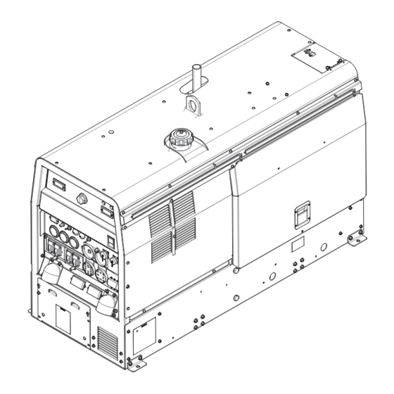
VANTAGE GENERAL DESCRIPTION ® GENErAL DESCrIPTION The VANTAGE 400 is a diesel engine powered DC ® multi-process welding power source and 120 / 240 volt AC power generator. The engine drives a generator that supplies three phase power for the DC welding cir- cuit, single phase and Three Phase power for the AC auxiliary outlets. -
Page 9: Installation
INSTALLATION VANTAGE INSTALLATION ® TECHNICAL SPECIFICATIONS - VANTAGE 400 (K2410-5) ® INPUT - DIESEL ENGINE Make/Model Description Speed (rPM) Displacement Starting Capacities PErKINS cu. in. (ltrs.) System 4 cylinder 135.6(2.2) 12VDC Battery & Fuel: 20 gal. 32.7 HP High Idle 1880 starter (75.7 L) (K2410-5) -
Page 10: Safety Precautions
SAFETY PrECAUTIONS VANTAGE INSTALLATION ® WArNING FIGUrE A.1 Do not attempt to use this equipment until you have thoroughly read the engine manufacturer’s (VRD)-VOLTAGE REDUCTION DEVICE SWITCH IS LOCATED IN THIS AREA. manual supplied with your welder. It includes important safety precautions, detailed engine starting, operating and maintenance instructions, and parts lists. -
Page 11: High Altitude Operation
VANTAGE INSTALLATION ® 1. Design capacity of trailer vs. weight of Lincoln equipment and WArNING likely additional attachments. 2. Proper support of, and attachment to, the base of the welding • Lift only with equipment of ade- equipment so there will be no undue stress to the framework. quate lifting capacity. -
Page 12: Oil
VANTAGE INSTALLATION ® NOTE: This machine is furnished with a wet charged bat- tery; if unused for several months, the battery may require a The VANTAGE 400 is shipped with the engine booster charge. Be careful to charge the battery with the crankcase filled with high quality SAE 10W-30 Oil that ®... -
Page 13: Electrical Connections
VANTAGE INSTALLATION ® is provided on the front of the welder. The 14-pin connector is used to directly connect a wire feeder control cable. In the CV-WIRE mode, when the control cable is WELDING TErMINALS connected to the 14-pin connector, the auto-sensing circuit The VANTAGE 400 is equipped with a toggle switch WArNING... -
Page 14: Standby Power Connections
VANTAGE INSTALLATION ® • Do not cross the welding cables at the output ter- NOTE: The 240 V receptacle has two 120 V circuits, minal connection. Keep the cables isolated and but are of opposite polarities and cannot be paral- separate from one another. -
Page 15: Premises Wiring
CONNECTION OF VANTAGE 400 TO PrEMISES WIrING VANTAGE INSTALLATION ® ® 240 VOLT GROUNDED CONDUCTOR POWER 240 Volt 120 VOLT 60 Hz. COMPANY 3-Wire 120 VOLT Service METER NEUTRAL LOAD DOUBLE POLE DOUBLE THROW SWITCH RATING TO BE THE SAME AS OR GREATER THAN PREMISES SERVICE OVERCURRENT PROTECTION. -
Page 16: Connection Of Lincoln Electric Wire Feeders
VANTAGE INSTALLATION ® FIGURE A.2 CONNECTION OF LINCOLN ELECTRIC WIRE FEEDERS Weld Set to Local Terminals On Set Mode to CONNECTION OF ACROSS THE ARC WIRE FEEDERS CV Wire TO THE VANTAGE ® These connections instructions apply to both the LN-25 Pro and Activ8 models. -
Page 17: Safety Precautions
VANTAGE INSTALLATION SAFETY PrECAUTIONS ® WArNING WArNING ADD FUEL Do not attempt to use this equipment until you • Stop engine while fueling. have thoroughly read the engine manufacturer’s • Do not smoke when fueling. manual supplied with your welder. It includes important safety precautions, detailed engine •... - Page 18 VANTAGE OPERATION ® FIGUrE B.1 WELDING CONTrOLS (Figure B.1) PUT CONTROL is used to preset the voltage. When in the TOUCH START TIG mode and when an 1. OUTPUT CONTrOL- Amptrol is connected to the 6-Pin Connector, the OUT- The OUTPUT dial is used to PUT dial is used to set the maximum current range of the preset the output voltage or current as displayed on the CURRENT CONTROL of the Amptrol.
- Page 19 VANTAGE OPERATION ® 10. WIrE FEEDEr VOLTMETEr SWITCH: 4. ArC CONTrOL - The ARC CONTROL dial is active in Matches the polarity of the wire feeder voltmeter to the CV-WIRE, CC-STICK and DOWNHILL PIPE modes, the polarity of the electrode. and has different functions in these modes.
-
Page 20: Engine Controls
VANTAGE OPERATION ® 17. ENGINE HOUr METEr- ENGINE CONTrOLS: Displays the total time that the engine has been running. This meter is useful for 12. rUN/STOP SWITCH - RUN position energizes the scheduling prescribed maintenance. engine prior to starting. STOP position stops the 18. -
Page 21: Constant Current (Stick) Welding
VANTAGE OPERATION ® NOTE: If the unit fails to start turn Run/Stop switch The ARC CONTROL dial sets the short circuit current (arc-force) during stick welding to adjust for a soft or to off and repeat step 3 through step 7 after crisp arc. -
Page 22: Tig Welding
VANTAGE OPERATION ® When in the TOUCH START TIG mode and when a The OUTPUT CONTROL dial adjusts the full output Amptrol is connected to the 6-Pin connector the OUT- range for pipe welding. PUT CONTROL dial is used to set the maximum cur- rent range of the current control of the Amptrol. -
Page 23: Wire Welding-Cv
VANTAGE OPERATION ® ArC GOUGING • Set the "WELDING TERMINALS" switch to the "REMOTELY CONTROLLED" position. This will keep the The VANTAGE 400 can be used for arc gouging. For opti- ® "Solid State" contactor open and provide a "cold" elec- mal performance, set the MODE switch to ARC GOUGING. -
Page 24: Accessories
FIELD INSTALLED OPTIONS / ACCES- VANTAGE ACCESSORIES ® WIrE FEEDEr OPTIONS SOrIES K449 LN-25 - Includes internal contactor for across the arc operation (no control cable). Provides “cold” electrode until K2641-2 FOUr WHEELED STEErABLE YArD TrAILEr gun trigger is pressed. Includes gas solenoid. For in plant and yard towing. -
Page 25: Maintenance
VANTAGE MAINTENANCE SAFETY PrECAUTIONS ® read the Safety Precautions in the front of this manual and in the Engine Owner’s Manual before WArNING working on this machine. • Have qualified personnel do all maintenance Keep all equipment safety guards, covers, and and troubleshooting work. -
Page 26: Engine Oil Change
VANTAGE MAINTENANCE ® ENGINE OIL CHANGE OIL FILTEr CHANGE Drain the engine oil while the engine is warm to assure • Drain the oil. rapid and complete draining. It is recommended that each time the oil is changed the oil filter be changed as •... - Page 27 VANTAGE MAINTENANCE ®...
-
Page 28: Cooling System
VANTAGE MAINTENANCE ® FUEL COOLING SYSTEM WArNING At the end of each day’s use, refill the fuel tank to min- imize moisture condensation and dirt contamination in HOT COOLANT can burn skin. the fuel line. Do not overfill; leave room for the fuel to expand. -
Page 29: Fuel Filter
VANTAGE MAINTENANCE ® CLEANING THE BATTErY FUEL FILTEr Keep the battery clean by wiping it with a damp cloth 1. Check the fuel filter and fuel pre-filter for water when dirty. If the terminals appear corroded, discon- accumulation or sediment. nect the battery cables and wash the terminals with an ammonia solution or a solution of 1/4 pound (0.1113 2. -
Page 30: Welder / Generator Maintenance
(3) hours or less, and it also • Service and repair should only be performed by automatically tests within (5) seconds of power to the Lincoln Electric Factory Trained Personnel. device. Unauthorized repairs performed on this equip- •... -
Page 31: Troubleshooting
HOW TO USE TrOUBLESHOOTING GUIDE WArNING Service and Repair should only be performed by Lincoln Electric Factory Trained Personnel. Unauthorized repairs performed on this equipment may result in danger to the technician and machine operator and will invalidate your factory warranty. For your safety and to avoid Electrical Shock, please observe all safety notes and precautions detailed throughout this manual. - Page 32 VANTAGE TROUBLE SHOOTING ® Observe all Safety Guidelines detailed throughout this manual PrOBLEMS POSSIBLE rECOMMENDED (SYMPTOMS) CAUSE COUrSE OF ACTION Major Physical or Electrical Damage 1. Contact your local Lincoln Authorized Field Service is Evident. Facility. Engine will not "crank". 1.
- Page 33 VANTAGE TROUBLE SHOOTING ® Observe all Safety Guidelines detailed throughout this manual PrOBLEMS rECOMMENDED POSSIBLE (SYMPTOMS) CAUSE COUrSE OF ACTION Engine shuts down while under a 1. High radiator coolant temperature. load. Reduce load if it is exceeding machine rating. Add coolant to system if low.
- Page 34 VANTAGE TROUBLE SHOOTING ® Observe all Safety Guidelines detailed throughout this manual PrOBLEMS POSSIBLE rECOMMENDED (SYMPTOMS) CAUSE COUrSE OF ACTION Engine will not go to high idle when 1. Auxiliary power load is less than using auxiliary power. 100 watts. Idler may not respond with less than a 100 watt load.
- Page 35 VANTAGE TROUBLE SHOOTING ® Observe all Safety Guidelines detailed throughout this manual PrOBLEMS POSSIBLE rECOMMENDED (SYMPTOMS) CAUSE COUrSE OF ACTION No welding power output. 1. Poor work lead connection to work. Make sure work clamp is tightly connected to clean base metal.
- Page 36 VANTAGE TROUBLE SHOOTING ® Observe all Safety Guidelines detailed throughout this manual PrOBLEMS POSSIBLE rECOMMENDED (SYMPTOMS) CAUSE COUrSE OF ACTION The welding arc is “cold.” The weld- 1. Make sure the MODE selector ing arc is not stable or is not satisfac- switch is in the correct position for tory.
- Page 37 VANTAGE DIAGRAMS ®...
- Page 38 VANTAGE DIAGRAMS ®...
- Page 39 VANTAGE DIAGRAMS ®...
- Page 40 VANTAGE DIAGRAMS ®...
- Page 41 VANTAGE DIAGRAMS ®...
- Page 42 VANTAGE DIAGRAMS ®...
- Page 43 VANTAGE DIAGRAMS ®...
- Page 44 VANTAGE DIAGRAMS ®...
- Page 45 VANTAGE NOTES ®...
- Page 46 nOteS Vantage ®...
- Page 47 WARNING Do not touch electrically live parts or Keep flammable materials away. Wear eye, ear and body protection. electrode with skin or wet clothing. Insulate yourself from work and AVISO DE ground. Spanish PRECAuCION No toque las partes o los electrodos Mantenga el material combustible Protéjase los ojos, los oídos y el bajo carga con la piel o ropa moja-...
- Page 48 WARNING Keep your head out of fumes. Turn power off before servicing. Do not operate with panel open or Use ventilation or exhaust to guards off. remove fumes from breathing zone. AVISO DE Spanish PRECAuCION Los humos fuera de la zona de res- Desconectar el cable de ali- No operar con panel abierto o piración.
- Page 49 Lincoln Electric for advice or information about their use of our products. We respond to our customers based on the best information in our possession at that time. Lincoln Electric is not in a position to warrant or guarantee such advice, and assumes no liability, with respect to such information or advice.