Baxi Bermuda 45/4 M Installation And Servicing Instructions
Hide thumbs
Also See for Bermuda 45/4 M:
- User's operating (8 pages) ,
- Servicing instructions (40 pages)
Table of Contents
Advertisement
Baxi Bermuda 45/4 & 57/4 Boilers
Gas Fired Central Heating Unit
Gas Type G20 (Natural Gas)
o
Comp N
241794 - Iss 9 - 6/00
Baxi Bermuda 45/4 M
Baxi Bermuda 57/4 M
Baxi Bermuda 45/4 E
Baxi Bermuda 57/4 E
These Instructions must be read in conjunction with those
for the separate Firefront.
o
-
G.C.N
44 077 71
o
-
G.C.N
44 077 72
o
-
G.C.N
44 077 73
o
-
G.C.N
44 077 74
Installation
And
Servicing
Instructions
Advertisement
Table of Contents

Related Manuals for Baxi Bermuda 45/4 M


Summary of Contents for Baxi Bermuda 45/4 M
-
Page 1: Servicing Instructions
Baxi Bermuda 45/4 & 57/4 Boilers Gas Fired Central Heating Unit Gas Type G20 (Natural Gas) Comp N 241794 - Iss 9 - 6/00 Baxi Bermuda 45/4 M G.C.N 44 077 71 Baxi Bermuda 57/4 M G.C.N 44 077 72 Baxi Bermuda 45/4 E G.C.N... - Page 2 Type test for purpose of Regulation 5 certified by: Notified Body 0086. We hope you get a satisfactory service from Baxi. If not, please let us know. Product/production certified by: Notified Body 0086. Baxi is a BS-EN ISO 9001...
-
Page 3: Table Of Contents
CONTENTS - Page 3 Introduction PAGE 4 Technical Data PAGE 5 PAGE 6 - 8 System Details Water Circulating Systems Treatment of Water Circulating Systems Pipework System Controls Fully Pumped System Overheat Kit & Sealed Systems Storage Systems Pumped Heating & Gravity Hot Water Site Requirements PAGE 9 - 12 Builders &... -
Page 4: Introduction
INTRODUCTION - Page 4 Description The Baxi Bermuda is a combined central heating boiler and gas fire designed for installation within a builders opening in the living space of a dwelling. These installation and servicing instructions cover all natural gas models. There are two physical sizes of boiler, the Bermuda 45 being the smaller. -
Page 5: Technical Data
TECHNICAL DATA - Page 5 Bermuda Boiler 57/4 Bermuda Boiler 45/4 Sedbuk Declaration For Bermuda 45/4 and 57/4 Boilers The seasonal efficiency (SEDBUK) are 45/4M 72.7% 45/4E 76.8% 57/4M 71.8% 57/4E 75.8% This value is used in the UK Government’s Standard Assessment Procedure (SAP) for energy rating of dwellings. -
Page 6: System Details
SYSTEM DETAILS - Page 6 Water Circulating Systems The appliance is suitable for open vented systems which are either fully pumped or pumped central heating with gravity domestic hot water. An overheat thermostat modification kit is available where additional control protection is required and for sealed system applications. - Page 7 SYSTEM DETAILS - Page 7 System Controls For optimum operating conditions, the heating system into which the appliance is installed should include a control system. Such a system would comprise a timer control and a separate room and/or cylinder thermostat as appropriate. The boiler should be controlled so that it operates on demand only.
- Page 8 (This must not be used on gravity systems.) Baxi Part N 235565 for Electronic Controls Baxi Part N 234885 for Manual Controls The boiler can be applied to a sealed system with the use of the overheat kit.
-
Page 9: Site Requirements
SITE REQUIREMENTS - Page 9 Builders & Fireplace Opening The boiler unit is designed to fit within a standard builders opening cavity, the minimum dimensions of which are 343mm(13½in) deep x 584mm(23in) wide x 584mm(23in) high. The opening should be soundly constructed of brick, pre- cast concrete or be a proprietary builders opening. - Page 10 SITE REQUIREMENTS - Page 10 FLUE Prior to installation it is important to establish that the flue will perform satisfactorily. Do not proceed with the installation if the flue does not operate correctly. The Bermuda is fitted with an Atmospheric sensing Device that will automatically shut the appliance down under adverse flue conditions and where insufficient flue pull exists.
- Page 11 SITE REQUIREMENTS - Page 11 Ventilation Ventilation air supply to BS 5440 Pt 2 is required. The permanent ventilation area size requirements are given in the firefront Installation and Servicing Instructions. The permanent vent may be directly into the room containing the appliance.
- Page 12 SITE REQUIREMENTS - Page 12 Functional Flow Diagram It is preferable to route the input cable from the left hand side of the builders opening. The cable can be secured to either the boiler base or fire support plate using the ‘P’ clip supplied in the kit. NOTE: Polarity of the appliance MUST be correct otherwise the appliance will not operate correctly.
- Page 13 INSTALLATION - Page 13 Initial Preparation Remove the outer carton and locate the fitting kit. Remove and discard the packing pieces and unpack the boiler hood. The hood may be fitted now or when the boiler is in situ. Use the four nuts and set screws provided.
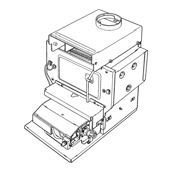
- Page 14 INSTALLATION - Page 14 Siting the Boiler The fireplace and builders opening should be as described under ‘site requirements’ and be clean, sound and level. The flue should be installed as described under ‘site requirements’. Locate the centre line of the opening and hearth. Hold the boiler by its combustion box at either side of the heat exchanger, lift from the packing base and place into the opening.
- Page 15 For systems requiring an overheat thermostat, a modification kit is available. The flow pipe arrangement for this type of installation is covered in the instructions supplied with that kit. Baxi Part N 235565 for 4514E & 57/4E Baxi Part N 234885 for 45/4M &...
- Page 16 INSTALLATION - Page 16 Pumped Heating & Gravity Hot Water A 1in x 22mm threaded adaptor, two compression nuts and olives and a brass injector tee piece are provided in the kit for the return connection. NOTE: The injector tee must be fitted to the return of all systems with gravity domestic hot water.
- Page 17 INSTALLATION - Page 17 Electrical Connection The appliance requires an electrical supply from the heating controls system. A permanent live is required for firefronts which have electronic ignition and/or light effects. WARNING The appliance must be earthed. The input cable for the appliance must be not less than 0.75mm to IEC 53 Code 227 (heat resistant).
- Page 18 INSTALLATION - Page 18 For installations requiring a permanent live ie:- where the firefront is equipped with either lighting effects or lighting effects and electronic ignition proceed as follows:- Connect the inlet supply cable(s) as indicated:- Permanent live to L Controls system switched live to SL Control system neutral to N Earth to...
- Page 19 INSTALLATION - Page 19 MANUAL CONTROL MODELS NOTE: The cover must be replaced after making electrical connections. Undo the screw retaining the socket cover and plug and socket to their mounting bracket. Disconnect the input socket from the controls plug. Remove the socket cover and inlet cable clamp.
- Page 20 INSTALLATION - Page 20 Refitting the Controls Take the controls assembly and locate the slots in the controls mounting bracket under the screws in the base tray. Align the .holes in the burner mounting plate with those in the combustion box sides and insert the screws. Tighten the four screws.
- Page 21 INSTALLATION - Page 21 MANUAL CONTROL MODELS Replace the combustion box door and secure with the screws previously removed. Ensure that the sensing pipe locates over the pilot breather sealing washer. The screws must be tight to achieve the required seal and to ensure correct operation of the Atmospheric Sensing Device.
- Page 22 INSTALLATION - Page 22 Flue Connection If not already fitted, secure the boiler hood to the combustion box using the 4 hexagon set screws and nuts from the kit. Locate the flue within the flue socket and secure with the three self tapping screws provided in the kit. Seal the flue into the flue outlet socket.
-
Page 23: Commissioning The Appliance
COMMISSIONING THE APPLIANCE - Page 23 Reference should be made to BS 5449 section 5 when commissioning the boiler and system. Flush the whole system in accordance with BS7593: 1992. (see System Details section of these instructions). Check for water leaks. Turn the gas service cock ¼... - Page 24 COMMISSIONING THE APPLIANCE - Page 24 ELECTRONIC CONTROLS MODELS On Electronic Controls models the pilot is intermittent and lights when the boiler thermostat is calling for heat. To operate the pilot turn the thermostat to HIGH. The burner will also light shortly after the pilot has been established. Electronic Control Models are fitted with a series of diagnostic indicator lights that indicate the status of the boiler.
-
Page 25: Annual Servicing
ANNUAL SERVICING - Page 25 To perform annual servicing of the back boiler it is necessary to remove the firefront. After servicing, complete the relevant section of the “Benchmark” Installation, Commissioning and Service Record Log Book. This should be in the possession of the user. - Page 26 ANNUAL SERVICING - Page 26 Manual Controls Models Remove the thermostat phial from the heat exchanger and carefully remove the capillary from its routing clips. Remove the controls heat shield from its retaining Remove the four screws retaining the combustion box door and remove the door.
-
Page 27: Cleaning The Pilot / A.s.d. Assembly
ANNUAL SERVICING - Page 27 Cleaning the Lint Arrestor Remove the lint arrestor from the controls and clean away any deposits. Cleaning the Burner and Main Injector Remove the four hexagon headed screws holding the burner to the burner mounting plate. Carefully clean any deposits from the burner blades and venturi inlet. -
Page 28: Cleaning The Heat Exchanger
ANNUAL SERVICING - Page 28 Cleaning the Heat Exchanger Remove the top baffle and the central baffles from the heat exchanger. Remove the side and rear insulation pieces by undoing the screws retaining the support brackets and sliding the rear bracket to the left and both side brackets forward. -
Page 29: Removal Of Firefront
CHANGING COMPONENTS - Page 29 To change any components on the back boiler it is necessary to remove the fire front. After changing any components carry out gas soundness checks. Removal of Firefront Isolate the electrical supply to the appliance and ensure the permanent live (when fitted) has also been isolated. -
Page 30: Gas Valve
CHANGING COMPONENTS - Page 30 Gas Valve ELECTRONIC CONTROL MODELS Remove the screw holding the valve cover to the controls mounting bracket and remove the cover. Disconnect the electrical connections from the valve, noting the position of each wire. Remove the two screws holding the valve to the controls mounting bracket adjacent to the union nut and tailpiece. - Page 31 CHANGING COMPONENTS - Page 31 MANUAL CONTROL MODELS Remove the control knob. Remove the screw holding the valve cover to the controls mounting bracket and remove the cover. Disconnect the electrical connections from the valve. Remove the two screws holding the valve to the controls mounting bracket adjacent to the union nut and tailpiece.
-
Page 32: Burner & Main Injector
The thermocouple cannot be changed as an individual component. The complete assembly must be replaced in the event of one or other component failure(s). Only use a Genuine Baxi Spare Part. Remove the controls heat shield from its clips if not already done so. -
Page 33: Thermostat
CHANGING COMPONENTS - Page 33 Thermostat MANUAL CONTROLS ONLY Remove the control knob. Undo the screw retaining the valve cover and remove the cover. Undo the locknut retaining the thermostat to the controls mounting bracket. Ease the thermostat away from the bracket and disconnect the electrical connections noting their positions. -
Page 34: Thermostat Sensor
CHANGING COMPONENTS - Page 34 Thermostat Sensor ELECTRONIC CONTROLS ONLY Undo the three screws retaining the control box cover and remove the cover. Disconnect the thermostat sensor plug from the PCB. Thermostat Potentiometer ELECTRONIC CONTROLS ONLY Remove the controls heat shield from its retaining clips if not already done so. -
Page 35: Printed Circuit Board
SHORT PARTS LIST - Page 35 G.C. Description Manufacturers Part No. 183 936 Igniter Piezo (M models) 040456 E01-683 Burner - Large 239376 Aeromatic AC02/011452 E01-682 Burner Small 239355 Aeromatic AC02/01 1453 378 845 Injector Burner 45/4 M 234511 Stereomatic B20 378 845 Injector Burner 45/4 E 234511... - Page 36 FAULT FINDING 57/4M & 45/4M - Page 36...
- Page 37 FAULT FINDING 57/4M & 45/4M - Page 37...
- Page 38 FAULT FINDING 57/4E & 45/4E - Page 38...
- Page 39 FAULT FINDING 57/4E&45/4E - Page 39...
- Page 40 FAULT FINDING 57/4E&45/4E - Page 40 Click here for Helplines...