Argox OS-214 plus User Manual
Desktop barcode printer
Hide thumbs
Also See for OS-214 plus:
- User manual (77 pages) ,
- User manual (39 pages) ,
- User manual (44 pages)
Table of Contents
Advertisement
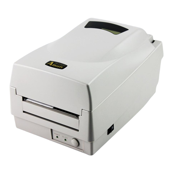
OS-214 plus
Desktop Barcode Printer
User's Manual
Proprietary Statement
This manual contains proprietary information of Argox Information Co., Ltd. It is
intended solely for the information and use of parties operating and maintaining the
equipment described herein. Such proprietary information may not be used, reproduced,
or disclosed to any other parties for any other purpose without the expressed written
permission of Argox Information Co., Ltd.
Product Improvements
Continuous improvement of products is a policy of Argox Information Co., Ltd. All
specifications and signs are subject to change without notice.
FCC Compliance Statement
This equipment has been tested and found to comply with the limits for a Class A
digital device, pursuant to Part 15 of the FCC Rules. These limits are designed to
provide reasonable protection against harmful interference in a residential installation.
This equipment generates, uses, and can radiate radio frequency energy and, if not
installed and used in accordance with the instructions, may cause harmful interference
to radio communications. However, there is no guarantee that the interference will not
occur in a particular installation. If this equipment does cause harmful interference to
radio or television reception, which can be determined by turning the equipment off and
on, the user is encouraged to try to correct the interference by the following measures:
•
Reorient or relocate the receiving antenna.
•
Increase the separation between the equipment and the receiver.
•
Connect the equipment into a different outlet on a different circuit.
•
Consult the dealer or an experience Radio/TV technician for help.
This unit was tested with shielded cables on the peripheral devices. Shielded cables
must be used with the unit to insure compliance. The user is cautioned that any changes
or modifications not expressly approved by Argox Information Co., Ltd. could void the
user's authority to operate the equipment.
Liability Disclaimer
Argox Information Co., Ltd. takes steps to assure that the company's published
engineering specifications and manuals are correct; however, errors do occur. Argox
Information Co., Ltd. reserves the right to correct any such errors and disclaims any
resulting liability. In no event shall Argox Information Co., Ltd. or anyone else involved
in the creation, production, or delivery of the accompanying product (including
hardware and software) be liable for any damages whatsoever (including, without
limitation, damages for loss of business profits, business interruption, loss of business
information, or other pecuniary loss) arising out of the use of or the results of use of or
inability to use such product, even if Argox Information Co., Ltd. has been advised of
the possibility of such damages.
I
Advertisement
Table of Contents

Related Manuals for Argox OS-214 plus


Summary of Contents for Argox OS-214 plus
-
Page 1: Product Improvements
Argox Information Co., Ltd. has been advised of the possibility of such damages. -
Page 2: Table Of Contents
A Letter to Our Customers Dear Customers, Congratulation on selecting an Argox OS series printer! We believe soon you will find that you have made a cleverest choice! This booklet is a small gift from us. It is intended for helping you to know your printer better, then further to optimize it. -
Page 3: Getting Started
Appendix II - Installing the Cutter... 74 Getting Started Congratulations on choosing the Argox OS-214 plus desktop barcode printer. This manual will help you get to know your new printer. There are two parts to this manual, an operation guide and related information. -
Page 4: Package Contents
Note the location of the Ribbon power jack for different models in the diagrams below. 2. Plug the other end of the cord into an AC electrical outlet. Power Switch AC Electrical Outlet Power Jack Barrel Connector Power Adapter OS-214 plus Cord... -
Page 5: Getting To Know Your Printer
Getting to Know Your Printer Parts and features of the OS-214 plus are illustrated below. Parts and Features Top Cover H Cover Power Indicator Ready Indicator Feed Button OS-214 plus Ribbon Pick-up Holder Power Switch Release Levers Ribbon Supply Holder... -
Page 6: Controls And Indicators
Controls and Indicators The printer’s controls and indicators are shown in the diagram Peel-Off Option Cutter Option below. The following table explains control and indicator functions. Top Cover Cutter White Plastic Roller Power Indicator Power Switch Ready Indicator Feed Button... -
Page 7: Loading Ribbon And Media
Loading Ribbon and Media This section describes how to load ribbon and media into the OS-214 plus printer. Loading a Ribbon Note: This section does not apply to direct thermal printing. 1. Lift the top cover to expose the media compartment. - Page 8 Media Compartment Print Head Module Release Lever Ribbon Supply Holder 4. Unwrap the ribbon roll pack and separate the ribbon roll and the bare core. 5. Attach the edge of the ribbon on the bare core and wind it a little bit onto the core. 6.
- Page 9 7. Put the print head module down and insert the bare core into the pick-up holder. (First snap in the left side, and then the right side.) Ribbon Pick-up Holder 8. Turn the wheel of the print head module to ensure the 9.
-
Page 10: Loading Media
Loading Media The OS-214 plus offers three different loading modes: standard, peel-off, or cutting. Standard mode allows you to collect each label freely. • Peel-off mode peels backing material away from the label • as it prints. After a label is removed, the next label prints. - Page 11 4. Click the media hanger back into the media compartment. 5. Align the media roll to the left end. 6. Move the shield from right to left until it leans against the media. Media Compartment Media Roll 7. Unlatch the print head module. 8.
-
Page 12: Peel Off Mode
10. Put the print head module down and press down firmly until you hear a snap. 11. Close the top cover and turn on the printer or press the "FEED" button if the printer is already on. Print Head Module Feed Button Peel Off Mode Note: For Peel-off mode you must first install the dispenser kit. - Page 13 10. Trim the front edge of the label backing paper with scissors or a knife. 11. Lead the backing paper over the dispenser bar, then thread it back into the slot between the dispenser bar and H cover, ensuring that it is inserted between the white plastic roller and platen roller.
-
Page 14: Cutting Mode
Note: The "FEED" button does not make the printer peel. Peeling occurs only when the software is properly set. Label Cutting Mode Note: For Cutting mode you must first install the cutter. Please refer to Appendix I. Follow Steps 1 to 8 listed in Standard Mode above. 9. -
Page 15: Configuration
11. Close the top cover and turn on the printer or press the "FEED" button if the printer is already on. Note: The "FEED" button does not make the printer cut. Cutting occurs only when the software is properly set. Configuration This section discusses calibration, printing configuration and resetting the printer to factory defaults. -
Page 16: Resetting To Factory Default Settings
Resetting to Factory Default Settings 1. Turn on the printer and wait for 5 or more seconds. 2. Press the "Feed" button for 10 seconds, and the "Ready" indicator and "Power" indicator will go off in order. 3. When the two indicators relight, release the feed button. 4. -
Page 17: Serial (Rs-232) Interface Requirements
Serial (RS-232) Interface Requirements The required cable must have a nine-pin "D" type male connector on one end, which is plugged into the mating serial port located on the back of the printer. The other end of the signal interface cable connects to a serial port on the host computer. -
Page 18: Communicating With The Printer
Communicating with the Printer The bundled printer driver can be applied to all applications under Windows 98/2000/NT, and Windows XP. With this driver you can run any popular Windows software applications such as MS-Word and print to this printer. Before Installation 1. - Page 19 Label Dr. 200 (or Label Dr. 300) driver and set it as the current printer driver: 3. If you install new bar code application software such as Bartender Ultra Lite, you should activate the seagull driver for Argox printer. ArgoBar File → New→ Select Printer→ Label Dr. on LPT1: → OK LabelView File→...
-
Page 20: Installing The Usb Driver (Plug And Play)
Installing the USB Driver (Plug and Play) Note: The printer driver needs to install version 1.4.00 or later and support “USB Plug and Play” for Windows XP, Windows 2003 and Windosw 2000. 1. Extract the PrinterDriver.exe to the fixed route. (“C:\Label Dr. 200”, for example) 2. - Page 21 6. Select “Continue Anyway”. 7. Click “Finish”. The Label Dr200 (4 inch model) printer is added in “Printers and Faxes”. 9. Reboot the system.
-
Page 22: Setting Parameters
More options To use the cutter or peeler function, enter (Accessories) More Options and select one of the items. Device options Set print speed. For the OS-214 plus, the (Speed) speed ranges from 1~ 3 ips. -
Page 23: Parameters For Win 98
Parameters for Win 98 Ports In the Properties menu: → Click "Details" → Select the IO port. → Click "OK" Paper size Orientation Paper source (Media type) Media choice (Darkness) Copies In the Properties menu: →Click "Paper" →Click items to select the desired parameters →Click "OK"... -
Page 24: Parameters For Win 2000
Create a custom size In the Properties menu: → Click "Paper" → Select "Custom" → User-Defined Size → Set a custom size → Click "OK" Parameters for Win 2000 Ports In the Properties menu: → Click "Ports" → Select the IO port →... - Page 25 Orientation Page order In Printing Preferences: → Click "Layout" → Select "Portrait" or "Landscape" → Click "Page order”" → Select "Front to Back" or "Back to Front" → Click "OK" Paper size Copies Print quality (Speed) Output bin (Accessory setting) In Printing Preferences: →...
-
Page 26: For Nt 4.0
Create a custom size In the Printers menu: → Right click → Select "Server Properties" → Enter a form name for in "Form Description for" → Reset paper size in "Measurements" → Click "OK" For NT 4.0 Ports In the Properties menu: →... -
Page 27: For Win Xp
Paper/Output (Speed) Print quality (Darkness) In Default Document: → Click "Advanced" → Click item to select desired parameters → Click "OK" Create a custom size Please refer to Create a custom size in Win 2000 above. For Win XP Ports In the Properties menu: →... - Page 28 Orientation Page order In Printing Preferences: → Click "Layout" → Select "Portrait" or "Landscape" → Click "Page order”" → Select "Front to Back" or "Back to Front" → Click "OK" Paper size Copies Print quality (Speed) Output bin (Accessory setting) In Printing Preferences: →...
-
Page 29: Troubleshooting
Create a custom size In the Printers menu: → Right click → Select "Server Properties" → Enter a “Form name” → Reset paper size in the "Form description" → Click "OK" Troubleshooting Normally, when the printer is in not working properly, the "Power" LED blinks continuously;... -
Page 30: Miscellaneous
LED Indicators: Power and Ready LEDs blink alternately Power LED Ready LED Possible Problems Solutions Ribbon out Supply the ribbon roll Ribbon jam Recover the jam Ribbon sensor error Replace ribbon sensor LED Indicators: Only the Power LED blinks Power LED Ready LED Possible Problems Solutions Serial IO error... -
Page 31: Recovery
Clean the print head. If the problem persists, replace the print head. Poor printout quality: The ribbon may not be qualified. • The media may not be qualified. • Adjust the Darkness (heat temperature). • Slow down the print speed. •... -
Page 32: Replacing The Thermal Print Head
Replacing the Thermal Print Head 1. Switch off the power and wait for both LEDs to go off. 2. Unlatch the print head module. 3. Remove the ribbon. 4. Push the print head firmly into the casing and shift it to the left. -
Page 33: Technical Reference
Technical Reference General Specifications Specification Model OS-214 plus Print method Direct thermal and thermal transfer Resolution 203 DPI (8 dots/mm) Max. print width 4.1 in. (104 mm) Max. print length 43 in (1092mm) Max. print speed 3 inches (76 mm) per second... -
Page 34: Fonts, Bar Codes And Graphics Specification
(PPL) through which the host communicates with your printer. There are two PPLs for models OS-214 plus. They are PPLA and PPLB. Note: Improper firmware updating may crash printer firmware. Please contact your supplier for assistance. -
Page 35: Interface Specifications
Interface Specifications USB series “B” Receptacle Interface Signal Name VBUS Connector Terminal Pin Assignment Serial For the OS-214 plus, the RS232 connector on the printer side is a female, DB-9. Direction Definition RxData TxData Ground Note: Pin 9 on the OS-214 plus is reserved for a KDU (keyboard device unit). -
Page 36: Parallel (Centronics)
The simplest way to connect to other hosts (not PC compatible) or terminals is: Printer Terminal/Host Pin 2- RxData ……… TxData Pin 3- TxData ……… RxData Pin 5- Ground ……… Ground In general, as long as the data quantity is not too large and you use Xon/Xoff as flow control, it will be problem free. -
Page 37: Ascii Table
ASCII TABLE " XOFF & ‛ < > Appendix I - Installing Dispenser Kit 1. Turn off the printer power and unplug the printer. 2. Unwrap the dispenser kit and take out screws, the shaft, Top Cover 3. Take off the top cover of the printer. 4. -
Page 38: Middle Cover
Sensor Cable Base Housing Base Housing Middle Cover 12. Release the screw on the left bracket of the chassis. 8. Release the two screws at the bottom of the base housing. 9. Remove the middle cover. 10. Take off the H. Cover. 11. - Page 39 13. Unlatch the print head module. Hook the white roller on the brackets of the chassis, ensuring the long thinner end is on the left side. 14. Guide the shaft through the respective holes on the left bracket, the white roller and then the right bracket in order. (To smooth this procedure, hold the white roller with one hand.) 15.
-
Page 40: Appendix Ii - Installing The Cutter
Appendix II - Installing the Cutter 1. Turn off the printer power and unplug the power cable and Centronics / Serial cable. 2. Remove the top cover. 3. Remove the two screws under the base housing. 4. Remove the whole print head assembly by releasing the 4 screws at its feet. - Page 41 6. Secure the four screws attaching the cutter. Cutter 7. Plug the cutter's connector into the PCB's header connector (JP16). 8. Reattach the print head assembly by securing the 4 screws. 9. Click back the middle cover. 10. Secure the two screws for the base housing. 11.