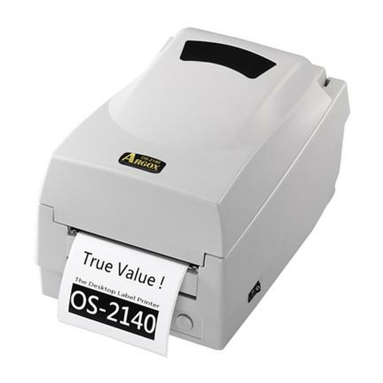
Argox OS-214plus User Manual
Desktop barcode printer
Hide thumbs
Also See for OS-214plus:
- User manual (77 pages) ,
- User manual (39 pages) ,
- User manual (46 pages)
Table of Contents
Advertisement
Quick Links
Download this manual
See also:
User Manual
Advertisement
Table of Contents

Related Manuals for Argox OS-214plus


Summary of Contents for Argox OS-214plus
- Page 1 ESKTOP ARCODE RINTER OS-214plus/OS-2140D/ OS-2140/OS-2140Z/ OS-2140DZ/OS-2140E User’s Manual 9001283 (A) - ENG Website: http://www.satoamerica.com...
-
Page 2: Safety
Proprietary Statement product, even if Argox Information Co., Ltd. has been advised of the possibility of This manual contains proprietary information of Argox Information Co., Ltd. It is such damages. -
Page 3: Table Of Contents
For Support Table of Contents For any issues or questions, contact SATO America, Inc. using the contact Safety ..................2 information shown here. Getting Started ..............6 Unpacking ..................6 Package Contents ..............7 Limitation of liability Connecting the Power Supply............8 SATO Corporation and/or its subsidiaries in Japan, the United States, and other Getting to Know Your Printer.......... -
Page 4: Getting Started
Media Sensor ...............61 Getting Started Thermal Print Head..............61 Replacing the Thermal Print Head........64 Congratulations on choosing the Argox Important notice during TPH replacement ....66 OS-214plus/OS-2140D/OS-2140/OS-2140Z/OS-2140DZ/ Technical Reference............67 OS-2140E desktop barcode printers. This manual will help you General Specifications .............67 get to know your new printer. There are two parts to this manual, Fonts, Bar Codes and Graphics Specification ......71... -
Page 5: Package Contents
Connecting the Power Supply Connect the power supply as below. WARNING! Do not operate the printer and power supply in an area where they can get wet. Make sure the power switch is in the "O" position. 1. Insert the barrel connector of the power supply into the power jack on the back of the printer. - Page 6 Power Cord OS-2140E OS-214plus...
-
Page 7: Getting To Know Your Printer
The illustrations that follow describe the printer’s parts, features, controls, and indicators. Parts and Features Ribbon Pick-up Holder Top Cover Media Hanger H Cover Ribbon module Release Levers (not included with OS-2140D) Power Switch Power Indicator Ready Indicator Feed Button OS-214plus/OS-2140D/OS-2140/OS-2140E/OS-2140Z/OS-2140DZ... -
Page 8: Controls And Indicators
Controls and Indicators The printer’s controls and indicators are shown in the diagram Ribbon Supply Holder below. The following table explains control and indicator Thermal Print head functions. Platen Roller Top Cover Power Switch Power Indicator Power Switch Ready Indicator Feed Button... -
Page 9: Loading Ribbon And Media
Loading Ribbon and Media Control / Function This section describes how to load ribbon and media in the OS Indicator Series printer. On: turns on normal operation Off: turns off power Loading Ribbon Power Switch Note: Turn power off before connecting or disconnecting cables Note: This section does not apply to direct thermal printing. - Page 10 Media Compartment 4. Unwrap the ribbon roll pack and separate the ribbon roll and the bare core. 5. Attach the edge of the ribbon on the bare core and wind it Print Head Module a little bit onto the core. 6.
- Page 11 7. Turn back the print head module and then insert the bare 8. Turn the wheel of the print head module to ensure the core into the pick-up holder. (First snap in the left side, and ribbon is tightly wound. then the right side.) 9.
-
Page 12: Loading Media
2. Remove the media hanger. Loading Media The OS-214plus/OS-2140D/OS-2140/OS-2140Z/OS-2140DZ/ OS-2140E printers offer Two different loading modes: standard or with a cutter. Media Compartment Media Hanger Standard mode allows you to collect each label freely. Cutter mode automatically cuts the label after it prints. - Page 13 4. Click the media hanger back into the media compartment. 7. Unlatch the print head module. 5. Align the media roll to the left end. 8. Hold the print head module upright with one hand to 6. Move the shield from right to left until it leans against the allow the media to pass under it.
-
Page 14: Cutter Mode
Cutter Mode 10. Put the print head module down and press down firmly Note: For Cutter mode you must first install the cutter and add until you hear a snap. the cutter baby board to J16 on the main board. Please 11. -
Page 15: Calibration And Configuration
11. Close the top cover and turn on the printer or press the Calibration and Configuration "FEED" button if the printer is already on. This section discusses calibration, printing configuration and Note: The "FEED" button does not make the printer cut. Cutting resetting the printer to factory defaults. -
Page 16: Resetting To Factory Default Settings
Resetting to Factory Default Settings Computer Connections 1. Turn on the printer and wait for 5 or more seconds. 2. Press the "Feed" button for 10 seconds, and the "Ready" Note: You must insert the power supply’s barrel connector into the power jack on the back of the printer before indicator and "Power"... -
Page 17: Serial (Rs-232) Interface Requirements
Serial (RS-232) Interface Requirements Serial Cabling Requirements The required cable must have a nine-pin "D" type male connector Data cables must be of fully shielded construction and fitted with on one end, which is plugged into the mating serial port located metal or metalized connector shells. -
Page 18: Parallel Interface Requirements
For pin-out information, Indicator to stop blinking and then can start to use printer. refer to the Reference Technical Information, Interface Specification. Power Jack Serial Port Parallel Port USB Port RS-232 Serial Port Ethernet Port (OS-2140E Model) USB Port OS-2140E OS-214plus... -
Page 19: Communicating With The Printer
With this driver you can operate any popular Speed LED Green LED On: 100 Mbps link Off: l0 Mbps link Windows software applications including Argox Bartender UL Link/Activity LED label editing software or MS Word, etc., to print to this printer. Amber LED... - Page 20 USB port on the printer and on the PC. 2. Turn on the printer. If the printer supports Plug-and-Play, and you have successfully connected it using a USB cable, then the Windows Add Hardware Wizard will automatically detect the printer and display a dialog that allows you to install a driver.
- Page 21 6. Enter Printer name (i.e. Argox OS-2140 PPLA) and select "do not share this printer”, and click "Next". Argox OS-2140 PPLA Argox OS-2140 PPLA Then click “Next.”...
- Page 22 7. Check all the data on the showing screen, if it is correct, click 8. After the related files have been copied to your system, click "Finish". "Finish". Argox OS-2140 PPLA USB002 Installing printer ‘Argox OS-2140 PPLA’… Argox OS-2140 PPLA 7.1.9_M-5...
-
Page 23: Installing The Printer Driver
Connect the USB cable, Serial cable, or Ethernet cable to the proper port on the printer and on your computer. Installed printer Argox OS-2140 PPLA 2. Prepare the documentation and software CD-Rom from printer package and then install to CD-Rom drive of your computer. - Page 24 3. Under OS-2140 product selection prompt, choose Seagull 4. On the prompt, Windows Printer Driver, select “I accept…” Driver version and then start installation: and click "Next". Instead of the flash prompt above, another way to install Seagull driver is to run the DriverWizard utility from the Installation Directory where the Seagull driver files are located.
- Page 25 6. Click "Finish". 5. Assign the directory to keep Seagull driver, (for example: C:\Seagull) and click "Next".
- Page 26 7. Select Install printer drivers and Click "Next" 8. Select model & emulation - the following examples are based on model OS-2140 PPLA: A rgox OS-2140 PPLA...
- Page 27 10. Enter Printer name (i.e. Argox OS-2140 PPLA) and select "do not share this printer”, and click "Next". 9. Select the port of the printer and click "Next". Argox OS-2140 PPLA...
- Page 28 11. Check all the data on the showing screen, if it is correct, click 12. After the related files have been copied to your system, click "Finish". "Finish". Argox OS-2140 PPLA USB001 Installing printer ‘Argox OS-2140 PPLA’… Argox OS-2140 PPLA 7.1.9_M-5...
-
Page 29: Troubleshooting
LED blinks continuously; while printing and communication between the host and printer stops. LED Diagnosis Installed printer Argox OS-2140 PPLA Power and Ready LEDs blinking continuously indicates printer errors. To understand the problem, please observe the Power and Ready LEDs and refer to the following solutions:... - Page 30 LED Indicators: Power and Ready LEDs blink alternately LED Indicators: Only the Ready LED blinks Power LED Ready LED Power LED Ready LED Possible Problems Solutions Remarks Possible Problems Solutions Remarks Print head too hot Printing will stop until the Ribbon out Supply the ribbon roll Not applicable to...
-
Page 31: Miscellaneous
Miscellaneous Poor printout quality: The ribbon may not be qualified. If the host shows "Printer Time out" The media may not be qualified. 1. Check if the communication cable (parallel or serial) is Adjust the Darkness (heat temperature). connected securely to your parallel or serial port on the ... -
Page 32: Caring For Your Printer
TPH Cleaning Interval: Caring for Your Printer It’s strongly recommended to regularly clean print heads at least when changing every one ribbon roll (in thermal transfer Adhesives and coatings of media can over time transfer onto the printing mode), or every one label roll (in direct thermal printing printer components along the media path including the thermal mode). -
Page 33: Replacing The Thermal Print Head
Replacing the Thermal Print Head 1. Switch off the power and wait for both LEDs to go off. 2. Unlatch the print head module. 3. Remove the ribbon. 4. Push the print head firmly into the casing and shift it to the left. -
Page 34: Important Notice During Tph Replacement
6. Disassemble the print head and the mounting bracket by Important notice during TPH replacement releasing screws. 1. Heater line should NOT be touched by bare hands to 7. Replace with a new print head. Reassemble the print head prevent any damage caused by ESD or corrosion. module in reverse order. -
Page 35: Technical Reference
Codabar, Code subset A/B/C, UCC/EAN-128, Specificatio OS-2140D OS-2140 OS-214plus UCC/EAN-128 K-MART, UCC/EAN-128 , Random Weight, Printing method Direct Transfer Direct Transfer/Thermal Transfer Plessey, HBIC, Telepen, FIM, UPC2, UPC5, GS1 Data Bar Printing 203 dpi (8dots/mm) PPLB: Code 39 (standard/with checksum digit),Code 93... - Page 36 Optional Items (Traditional Chinese, Simplified Chinese, Korean and only), QR code, Composite codes Japanese) 2D Barcodes OS-214plus: Agency Listing PPLA: PDF-417, MaxiCode, Data Matrix (ECC200 only) ,QR CE, FCC, cTUVus, CCC, Code, Composite codes PPLB: MaxiCode, PDF-417, QR Code, Composite codes OS-2140 &...
-
Page 37: Fonts, Bar Codes And Graphics Specification
Printer Programming Language B, PPLB Fonts, Bar Codes and Graphics Specification Programming The specifications of fonts, bar codes and graphics depends on PPLB Language the printer emulation. The emulations PPLA, PPLB and PPLZ are Internal fonts 5 fonts with different point size printer programming languages, through which the host can 8 bits code page : 437, 850, 852, 860, 863, 865, communicate with your printer. -
Page 38: Printer Programming Language Z, Pplz
Printer Programming Language Z, PPLZ Notes: 1. The bare core for the ribbon must be 11 cm in length. It Programming should have two opposite slits at two ends. If the ribbon PPLZ Language itself is less than 11 cm, it must be aligned with the bare 8 (A~H) fonts with different point size. -
Page 39: Interface Specifications
Interface Specifications Serial The RS232 connector on the printer side is a female, DB-9. USB Interface Direction Definition This is port complies with USB 2.0 Full Speed. Shorted to Pin 6 RxData Connector Terminal Pin Assignment TxData Signal Description N.C. VBUS Ground Differential data signaling... -
Page 40: Ethernet
Ethernet Parallel (Centronics) The following port complies with Ethernet communication. The parallel port is a standard 36-pin Centronics, which complies with IEEE 1284 standard (compatibility mode). Pin assignments Signal are as follows: Transmit+ Transmit- Direction Definition Direction Definition Receive+ n/STROBE Ground Reserved Chassis... -
Page 41: Connection With Host
Connection with host Printer Terminal/Host Pin 2- RxData ……… TxData Pin 3- TxData ……… RxData Host 25S Printer 9P Host 9S Printer 9P Pin 5- Ground ……… Ground (PC or compatible) (PC or compatible) In general, as long as the data quantity is not too large and you DTR 20 ……... -
Page 42: Appendix I - Installing The Cutter
Appendix I - Installing the Cutter 4. Remove the whole print head assembly by releasing the 4 screws at its feet. 1. Turn off the printer power and unplug the power cable and Serial / USB cable. 2. Remove the top cover. 3. -
Page 43: Appendix Ii - Installing The Extension Card
Appendix II - Installing the Extension Card 6. Secure the four screws attaching the cutter. Extension Card designated for all optional extension modules. For example, RTC card and Add-on card. Install the extension card into the printer as follows: 1. Turn off the printer power. 2. - Page 44 4. Remove the middle cover. 5. Mount the extension card to J14 on the main board. Slot for Extension card 6. Click back the middle cover. 7. Secure the two screws for the base housing. 8. Click the top cover into place.