Table of Contents
Advertisement
10" Variable Speed Drill Press
(Model DP250)
PART NO. 906771 - 07-01-02
Copyright © 2002 Delta Machinery
To learn more about DELTA MACHINERY
ESPAÑOL: PÁGINA 17
visit our website at: www.deltamachinery.com.
For Parts, Service, Warranty or other Assistance,
1-800-223-7278 (
1-800-463-3582).
please call
In Canada call
Advertisement
Table of Contents

Related Manuals for Delta ShopMaster DP250


Summary of Contents for Delta ShopMaster DP250
- Page 1 10" Variable Speed Drill Press (Model DP250) PART NO. 906771 - 07-01-02 Copyright © 2002 Delta Machinery To learn more about DELTA MACHINERY ESPAÑOL: PÁGINA 17 visit our website at: www.deltamachinery.com. For Parts, Service, Warranty or other Assistance, 1-800-223-7278 ( 1-800-463-3582).
-
Page 2: General Safety Rules
If you have any questions relative to a particular application, DO NOT use the machine until you have first contacted Delta to determine if it can or should be performed on the product. -
Page 3: For Drill Presses
ADDITIONAL SAFETY RULES FOR FOR DRILL PRESSES WARNING: FAILURE TO FOLLOW THESE RULES MAY RESULT IN SERIOUS PERSONAL INJURY. 1. DO NOT OPERATE THIS TOOL UNTIL it is 14. TURN THE MACHINE “OFF” AND WAIT FOR THE assembled and installed according to the DRILL BIT, CUTTING TOOL, OR SANDER TO instructions. -
Page 4: Motor Specifications
POWER CONNECTIONS A separate electrical circuit should be used for your machines. This circuit should not be less than #12 wire and should be protected with a 20 Amp time lag fuse. If an extension cord is used, use only 3-wire extension cords which have 3- prong grounding type plugs and matching receptacle which will accept the machine’s plug. -
Page 5: Extension Cords
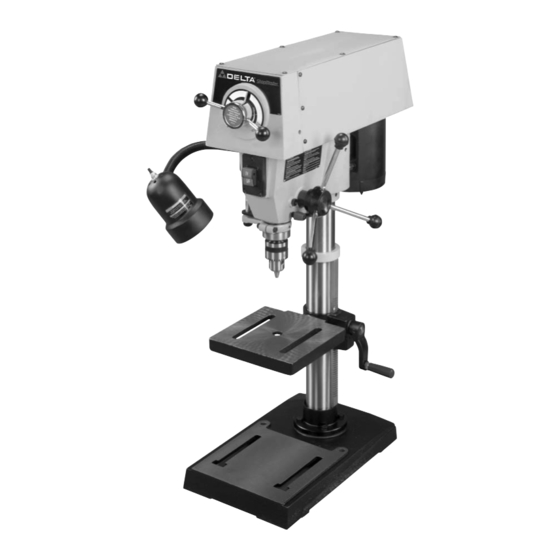
FOREWORD Delta ShopMaster Model DP250 is a 10", variable speed, bench drill press with a flexible work lamp. The Model DP250 allows the operator to quickly and easily change the drill speeds without removing the cover and adjusting belts. The Delta ShopMaster Model DP250 is a valuable tool for any workshop. - Page 6 DRILL PRESS PARTS Fig. 2 Fig. 1 Fig. 1 Fig. 2 5 - Chuck 1 - Drill Press Head and Motor 6 - Clamp Handle 2 - Column, Base Flange, and Rack 7 - Pinon Shaft Handles (3) 3 - Table 8 - Table Raising and Lowering Handle 4 - Base 9 - M8x1.25x125mm Carriage Head Screws (2),...
- Page 7 ASSEMBLY WARNING: FOR YOUR OWN SAFETY, DO NOT CONNECT THE MACHINE TO THE POWER SOURCE UNTIL THE MACHINE IS COMPLETELY ASSEMBLED AND YOU READ AND UNDERSTAND THE ENTIRE INSTRUCTION MANUAL. 1. Assemble the column (A) Fig. 3, to the base (B) using the four screws, three of which are shown at (C).
- Page 8 4. Slide raising rack (F) Fig. 7, table and table bracket onto drill press column, as shown. Make sure bottom of Fig. 7 raising rack (F) Fig. 8, is inside the flange (J) on drill press base. 5. Re-assemble ring (E) Fig. 9, which was removed in STEP 1.
- Page 9 7. Thread stud on clamp handle (M) Fig. 12, into hole in rear of table bracket, as shown. Fig. 12 8. Place the drill press head (N) Fig. 13, onto the column as far as it will go. Align head (A) Fig. 13A, to table (B), and base (C).
-
Page 10: Operating Controls And Adjustments
10. IMPORTANT: Make certain the spindle taper (Q) Fig. 15, and tapered hole in chuck (R) are clean and free of any grease, lacquer or rust preventive coatings. NOTE: Household oven cleaner can effectively remove any sub- stance from the spindle and chuck; however, carefully follow the manufacturer's safety rules concerning its use. -
Page 11: Table Adjustments
FLEXIBLE LAMP The flexible lamp operates independently of the drill press. To turn the lamp “ON” and “OFF”, rotate switch (A) Fig. 18A. WARNING: To reduce the risk of fire, use 40 watt or less, 120 volt, reflector track type light bulb (not supplied). -
Page 12: Variable Speed Control
VARIABLE SPEED CONTROL IMPORTANT: To avoid damaging the drive belts and pulleys, DO NOT turn speed control handles (A) Fig. 24, unless motor is running. The pilot wheel handles (A) are turned clockwise to increase speed and counterclockwise to decrease speed. The speed range is 500 rpm to 3100 rpm. -
Page 13: Adjusting Spindle Return Spring
Use scrap material for practice to get a feel of the machine before attempting regular work. WARNING: The use of accessories and attachments not recommended by Delta may result in risk of injury. IMPORTANT: When the workpiece is long enough it should always be positioned on the table with one end against the left side of the column, as shown in Fig. -
Page 14: Correct Drilling Speeds
INSTALLING AND REMOVING DRILL BITS 1. DISCONNECT MACHINE FROM POWER SOURCE. 2. Insert smooth end of drill bit (A) Fig. 29, into chuck (B), as far as it will go, and then back the bit out 1/16", or up to the flutes for small bits. 3. -
Page 15: Maintenance
MAINTENANCE LUBRICATION 1. DISCONNECT MACHINE FROM POWER SOURCE. 2. Remove the six screws (A) Fig. 30 that hold the top cover in place, and remove the top cover. 3. The variable speed pulleys should be oiled weekly with a few drops of light machine oil in the two oil holes (B) Fig. -
Page 16: Parts, Service Or Warranty Assistance
Two Year Limited Warranty Delta will repair or replace, at its expense and at its option, any Delta machine, machine part, or machine accessory which in normal use has proven to be defective in workmanship or material, provided that the customer returns the product prepaid to a Delta factory service center or authorized service station with proof of purchase of the product within two years and provides Delta with reasonable opportunity to verify the alleged defect by inspection.