Table of Contents
Advertisement
Quick Links
Download this manual
See also:
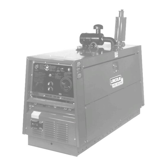
Operator's Manual
IMA 523D
OPERATING MANUAL
SHIELD-ARC
SAM-400
®
KA 1355
SAFETY DEPENDS ON YOU
Lincoln welders are designed and built with safety in mind. However, your overall safety can be increased
by proper installation . . . and thoughtful operation on your part. Read and observe the general safety
precautions on page 2 and follow specific installation and operating instructions included in this manual.
Most importantly, think before you act and be careful.
THE LINCOLN ELECTRIC COMPANY
(AUSTRALIA) PTY. LTD.
A.C.N. 000 040 308
SYDNEY. AUSTRALIA
A Subsidiary of
THE LINCOLN ELECTRIC CO. U.S.A.
Associated Subsidiaries in Australia, Europe, Asia, North and South America.
THE WORLD'S LEADER IN WELDING AND CUTTING PRODUCTS
Advertisement
Table of Contents

Related Manuals for Lincoln Electric Shield-Arc SAM400


Summary of Contents for Lincoln Electric Shield-Arc SAM400
-
Page 1: The Lincoln Electric Company
Most importantly, think before you act and be careful. THE LINCOLN ELECTRIC COMPANY (AUSTRALIA) PTY. LTD. A.C.N. 000 040 308 SYDNEY. AUSTRALIA A Subsidiary of THE LINCOLN ELECTRIC CO. U.S.A. Associated Subsidiaries in Australia, Europe, Asia, North and South America. THE WORLD'S LEADER IN WELDING AND CUTTING PRODUCTS... - Page 2 PROTECT YOURSELF AND OTHERS FROM POSSIBLE SERIOUS INJURY OR DEATH. READ AND UNDERSTAND BOTH THE SPECIFIC INFORMATION GIVEN IN THE OPERATING MANUAL FOR THE WELDER AND/OR OTHER EQUIPMENT TO BE USED AS WELL AS THE FOLLOWING GENERAL INFORMATION. ARC WELDING SAFETY PRECAUTIONS ARC RAYS can burn ELECTRIC SHOCK can kill 1.
- Page 3 3. Parts should be ordered from The Lincoln Electric Company, its offices or the nearest Authorised Field Service Shop. (The “Lincoln Service Directory” listing these shops geographically is available on request.) * “Hardware”...
- Page 4 WELDING EMF AND PACEMAKERS All welders should follow safe practices that minimise their Welders with Pacemakers exposure to electric and magnetic fields (EMF). There is no question that the fields in arc welding can interfere For welders wearing implanted pacemakers, safe welding with a pacemakers function.
- Page 5 INSTRUCTIONS FOR ELECTROMAGNETIC COMPATIBILITY Methods of Reducing Emissions WARNING Maintenance of the Welding Equipment This welding machine must be used by trained operators only. The welding equipment should be routinely maintained Read this manual carefully before attempting to use the according to the manufacturer’s recommendations.
- Page 6 SPECIFICATIONS ENGINE WELDER Model Specification No. Perkins 4/236 Diesel KA-1355 Capacity 3.9 litres (236 cu. ins.) Model Shield-Arc ® SAM400 Lubrication High pressure forced feed Rated Output 400 amps @ 40 arc volts and from rotary type oil pump 60% duty cycle (exceeds Cooling Water cooling with circulation AS1966 requirements)
- Page 7 If the oil pressure gauge does not show normal oil TO STOP THE ENGINE pressure (207/414kPa) 10 seconds after starting, Turn the key switch to “O” position. The engine speed stop the engine and consult the engine instruction has been pre-set in the factory for optimum welder manual.
- Page 8 USE OF WELDERS AS STAND-BY POWER UNITS actual welding voltage, the arc must be established. Welders with 240 volt 60Hz auxiliary AC outlets can be Constant Voltage Welding with Variable Inductance used as stand-by power units. To avoid the possibility of Control electric shock and/or damage to the welding machine, Variable inductance or slope control is usually required...
- Page 9 IMPORTANT SAFETY INSTRUCTIONS BATTERY FILLING AND SERVICE INSTRUCTIONS • Battery electrolyte contains SULPHURIC ACID which is corrosive to skin and clothing. TO GAIN ACCESS TO BATTERIES: • Batteries also contain EXPLOSIVE GASES. Remove the lower rear panel (radiator end). • Do not do anything to cause sparks near the battery. NOTE: Batteries must not be filled or “Topped Up”...
-
Page 10: Ground Test Procedure
Commutators and slip rings require little attention. contact is made across the full face of the brushes. However, if they are black or appear uneven, have an After stoning blow out the dust with low pressure air. experienced maintenance man clean them with fine CAUTION: Uncovered rotating equipment can be sandpaper or a commutator stone. - Page 11 AM2530-1 NOTES: N.A. Extend lead 21 using 2.5mm or larger insulated wire physically suitable for the installation. An S16586-[ ] remote voltage sensing work lead is available for this purpose. Connect it directly to the work piece keeping it electrically separate from the welding work lead circuit and connection.
- Page 12 AM2530-1 LN21 1. Turn off the engine and connect the KA1379 control cable from the LN21 to the welder terminal strip exactly as shown in the drawing. 2. The Portable Field Control shipped with the SAM Welder must be connected as shown. If this is not done there will be no control of the machine output.
- Page 13 VARIABLE STICK ELECTRODE WELDING VOLTAGE (VARIABLE VOLTAGE) 1 Set Toggle switch to “Variable Voltage”. CONSTANT 2 Set “Electrode Polarity” to “Variable Voltage – Positive” or “Variable Voltage – Negative” as desired. VOLTAGE 3 Set “Current Control” for approximate current desired using the high scale. 4 Use “Variable”...
- Page 14 VARIABLE INNERSHIELD AND MOST OTHER VOLTAGE OPEN ARC WELDING (CONSTANT VOLTAGE) CONSTANT Set Toggle switch to “Constant Voltage”. VOLTAGE Set “Electrode Polarity” on “Constant Voltage – Positive” or “Constant Voltage – Negative” as desired. Set “Constant Voltage” range selector to “11 to 18 arc volts' position, if operating in this range. Set “Constant Voltage”...
-
Page 15: Troubleshooting Guide
TROUBLESHOOTING GUIDE Use in conjunction with Wiring Diagram AL2341 and Schematic Diagram AL2342 NOTES: (A) If at any time the PCB is replaced, follow the calibration procedure outlined at the end of this guide. The OCV will be out of range if trimmers are not properly set. If both lower limit trimmers are set at minimum, the machine may lose excitation. - Page 16 Continuity Check. 1) Turn off machine. 2) Remove all leads and plugs from PCB. 3) Place electrode polarity switch in constant voltage positive position. 4) Place toggle switch to mode in question. 5) Check continuity of the following. Mode in Question. Constant Voltage.
- Page 17 P.C.B. CALIBRATION (VARIABLE VOLTAGE) P.C.B. CALIBRATION (CONSTANT VOLTAGE) The toggle switch must be at variable voltage and both the variable Turn both constant voltage control and portable field control to voltage control and the portable field control set at High. Locate High.
-
Page 18: Wiring Diagram
Wiring Diagram A10-7-91 Page 18 Shield-Arc SAM-400 IMA 523D... -
Page 19: Schematic Diagram
Schematic Diagram This diagram is typical of the machine’s wiring. For specific detail refer to the diagram attached to the machine itself. If the diagram has been destroyed or defaced, contact the factory quoting the machine’s serial number and code number from the nameplate. A10-7-91 IMA 523D Shield-Arc SAM-400... - Page 20 GENERAL ASSEMBLY AP-27-C Note:In all Parts lists, left and right hand side should be determined while standing facing The Generator end of the welder. 20, 15, 16, 17 53,54 30, 31 26, 27 11,60 14 12,20 8, 34 46,47,48 When ordering parts, quote machine serial number and code number, Parts List Number, Item Number and Description. Quote AP-27-C plus Machine Code No.
- Page 21 AP-27-C.1 When ordering parts, quote machine serial number and code number, Parts List Number, Item Number and Description. Quote AP-27-C plus Machine Code No. and Serial No. Quote AP-27-C plus Machine Code No. and Serial No. Item Part Name and Description Req’d Item Part Name and Description...
- Page 22 ELECTRONIC – COMPONENT PANEL ASSEMBLY AP-36-E.1 (FIELD REGULATOR) AL-1966 11/7/90 When ordering parts, quote machine serial number and code number, Parts List Number, Item Number and Description. Quote AP-36-E1 plus Machine Code No. and Serial No. Quote AP-36-E1 plus Machine Code No. and Serial No. Item Part Name and Description Item...
- Page 23 CONTROL PANEL & OUTPUT STUD ASSEMBLY AP-36-D Ref: AM 3060-I (A28-2-93) AL 2345 (A28-4-88) Hex. Nut Section A-A Rd Hd Screw Hex. Nut Starwasher Section A-A Earth Screw Detail Rd Hd Screw AM3040-37 AM3040-37 AM3040-270 AM3040A282 Starwasher Earth Screw Aux. 240V 115V Outlet...
- Page 24 ALTERNATOR ASSEMBLY, ALTERNATOR BRUSH HOLDER AND DIODE HEAT SINK ASSEMBLY Figure 1: Alternator Assy. see AP-27-G Figure 2: Alternator Brush Holder Figure 3: Diode Heat Sink Assy. see AP-27-G see AP-36-F Ref. No. AL 1948 (A2-3-94M) When ordering parts, quote machine serial number and code number, Parts List Number, Item Number and Description. Parts List AP-27-G Parts List AP-36-F Item...
- Page 25 WELDING GENERATOR AND COUPLING AP-27-F FOR ALTERNATOR PARTS SEE AP-27-G When ordering parts, quote machine serial number and code number, Parts List Number, Item Number and Description. Quote AP-27-F plus Machine Code No. and Serial No. Item Part Name and Description Item Part Name and Description Req’d...
- Page 26 FRAME, FUEL, TANK AND REACTOR AP-33-E (plan view) When ordering parts, quote machine serial number and code number, Parts List Number, Item Number and Description. Quote AP-33-E plus Machine Code No. and Serial No. Item Part Name and Description Item Part Name and Description Req’d Req’d...
- Page 27 GENERATOR BRUSH HOLDER AP-9-G Parts List AP-9-G Item Part Name and Description Req’d Brush holder Assy., includes ......Brush holder Stud ........Retainer Assembly........Washer............Insulating Washer ........Insulating Tube ........... Washer............Spring Clip ..........Spring............Lockwasher (3/8") ........Hex. Head Bolt (3/8" W x 3/4") ....Hex.
- Page 28 S-78 STARTER AP-27-L STARTERS ARE EITHER S-67 OR S-78 CONTACTORS Not all parts are interchangeable. When ordering parts identify them as for S-67 or S-78, which will be marked either on vertical leg of Item 1 or Item 5. Also advise Input Supply. S-78 CAN BE USED IN PLACE OF S-67 COMPLETE Quote AP-27-L (1/6/86) plus Machine Code No.
- Page 29 UNDERCARRIAGE ( 2-wheel type) AP-22-A Tow-eye for undercarriage W/o brakes shown only AL-1870 UNSPRUNG TYPE (25/5/83) AL-1871 SPRUNG TYPE (27/2/85) Optional brake mechanism shown in hidden detail When ordering parts, quote machine serial number and code number, Parts List Number, Item Number and Description. Quote AP-22-A plus Machine Code No.
- Page 30 UNDERCARRIAGE ( 4-wheel type) AP-89 Chassis Channel Spring Manager When ordering parts, quote machine serial number and code number, Parts List Number, Item Number and Description. Item Part Name and Description Req’d Front Axle ............Rear Axle............Front Spring – 3 leaf.......... Rear Spring –...
- Page 31 NOTES IMA 523D Shield-Arc SAM-400 Page 31...
- Page 32 WARRANTY The Lincoln Electric Company (Australia) Pty Limited (“Lincoln”) warrants all new At the date of this warranty the details of those manufacturers warranties are as machinery and equipment (“goods”) manufactured by Lincoln against defects in follows: workmanship and material subject to certain limitations hereinafter provided.