Vertex Standard VXR-7000 Operating Manual
25 watt fm repeater
Hide thumbs
Also See for VXR-7000:
- Service manual (146 pages) ,
- Operating manual (44 pages) ,
- Alignment manual (4 pages)

Related Manuals for Vertex Standard VXR-7000


Summary of Contents for Vertex Standard VXR-7000
- Page 1 VXR-7000 Operating Manual DESKTOP REPEATER POWER BUSY ANI RESET REPEATER REMOTE VXR 7000 BASE LOCAL MONITOR ACCESSORY Vertex Standard LMR, Inc.
-
Page 2: Table Of Contents
Contents Introduction............................1 Controls.&.Connectors..........................2 Front Panel .............................2 Rear Panel ............................3 ACC.Connector.Port..........................4 LINE.Interface.Port..........................6 Installation..............................7 Antenna Considerations ......................7 DC Power Supply Backup ......................7 Equipment Location ........................7 CE27.Programming.Software.Instruction..................8 Duplexer.Installation..........................12 Specifications............................14 Accessories............................15 Attention.in.case.of.use This repeater works on frequencies which are not generally per- List of the Practicable Area mitted. For frequency allocation, apply for a licence at your local spec- trum management authority. -
Page 3: Introduction
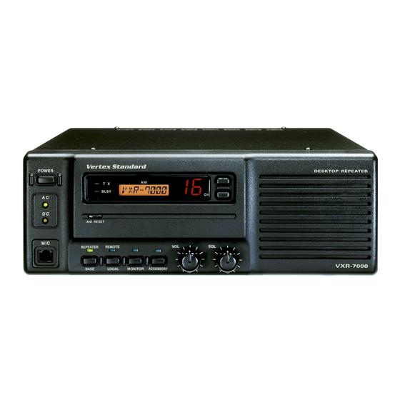
DESKTOP REPEATER POWER BUSY ANI RESET REPEATER REMOTE VXR 7000 BASE LOCAL MONITOR ACCESSORY The VXR-7000 is commercial quality 25-watt FM repeater designed to provide reliable, continuous-duty two- way communications over a wide range of environmental conditions. Designed to be a stylish base station, with high-grade components utilized throughout, the VXR-7000 utilizes the latest computer-aided design and manufacturing processes to ensure a high level of reliability for users. Im- portant channel frequency data is stored in EEPROM, and is easily programmable by a Servicing Technician or Dealer using an IBM compatible personal computer and the FIF-10A (or FIF-12) + CT-104A USB Programming Interface and CE27 Software. Please take a few minutes to read this manual carefully. The information presented here will allow you to derive maximum performance from your VXR-7000. After reading it, keep this manual handy for quick reference, in case questions arise later on. Important Note: Internal service work, programming, and accessory installations should only be performed by your authorized Vertex Standard Dealer. Dangerous conditions and/or possibly illegal operation may result... -
Page 4: Controls.&.Connectors
“REMOTE” mode and “LOCAL” mode. When ⑨.SQL Knob the “LOCAL” mode is selected, the LED above it This control knob selects the noise squelch thresh- is off, and the repeater operates according to the old level. Set it to a position just above the point control data programmed into the repeater. While where the BUSY lamp goes out when no signal is in the “REMOTE” mode, the LED glows green, present. and the repeater operates according to the con- trol instructions received from an external device ⑩ Channel Selector Buttons ( and ) (connected to the ACC jack on the rear panel). Press one of these buttons to select the operating channel. VXR-7000 FM Repeater Operating Manual... -
Page 5: Rear Panel
12 volts, 55 Ah (minimum) is recommended for ④.ACC Jack short-term emergency/backup operation. This DB-25 connector provides a data interface Never short-circuit these terminal while operat- between the microprocessor in the VXR-7000 and ing from AC mains. peripheral devices (such as the VX-TRUNK Unit). VXR-7000 FM Repeater Operating Manual... -
Page 6: Acc.connector.port
ACC Connector Port Pin 8: RSSI [ Analog Output ] The VXR-7000 repeater is provided with a 25-pin DB-25F female connector for interconnections to ac- A DC voltage proportional to the strength of the cessories. Use a DB-25M 25-pin male connector to signal currently being received (Receiver Signal connect accessories to the repeater. The pins on the Strength Indicator) is provided on this pin. This... - Page 7 Channel ( D3 ) ( D2 ) ( D1 ) ( D0 ) pre-emphasis and limiting stage, so excess signal input levels are clipped. Pin 25: TXD HI [ Digital Input for the DATA Communications ] This pin is intended to be used as a high speed digital data signal input to the repeater. This digi- tal data signal is injected after transmitter splatter filter stage. VXR-7000 FM Repeater Operating Manual...
-
Page 8: Line.interface.port
LINE Interface Port Pins 5 & 6: [ LINE OUT ( Rx Line Audio )] The VXR-7000 is provided with an 8-pin modular jack for line interfacing applications. A Western Receiver audio is available from this pair, subject ® Electric modular-type RJ45 plug should be used to to internal CTCSS or DCS decode if the received connect to this jack. The LINE jack pin-out is shown signal strength is above the squelch threshold. below. As shipped from the factory, a 1-kHz receiver sig- nal with standard deviation gives ‒10 dBm on the Note that there are both 4-line and 8-line types of line, but this can be varied by VR4002 and S4001 modular plugs. If a 4-line modular plug is used,... -
Page 9: Installation
Do not place equipment, books, or papers on top and bottom of the repeater. Also, provide 30 centimeters of space on either side of the repeater. Protect the repeater from wind and rain, and ex- tremes in temperature or humidity that may shorten the useful life of the equipment. Try to locate the re- peater in an environment that is also comfortable for service personnel, if possible. VXR-7000 FM Repeater Operating Manual... -
Page 10: Ce27.Programming.software.instruction
Important.Note! quickly and easily program the Vertex Standard . Do. not. run. the. original. CE27. program- VXR-7000 repeater ’s channels and configuration ming. software. directly.. Copy. the. pro- from your personal computer. Channel data pro- gramming. software. to. your. computer’s. - Page 11 This function is only used to move a spurious re- Double-click the left mouse button to toggle “on” sponse “birdie” should it fall on a current frequency. or “off”. When this parameter is set to “on”, this Double-click the left mouse button to toggle “yes” or function causes the VXR-7000 to send out a “blip” “no”. on the portable/mobile radio is frequency each time the portable radio is unkeyed. This provides audible NSQ Mode: [ Noise Squelch Mode ]...
- Page 12 ”BCLO” inhibits transmitting while there is carrier ming. present. “BTLO” inhibits transmitting while there is carrier present unless there also is a valid tone pres- Action Mode: [ Select the repeater operation mode ] ent. Double-click the left mouse button to toggle between “Duplex” operation or “Simplex” operation. Tx Freq.: Edit Transmit Frequency Use the [ 0 ] - [ 9 ] keys to enter the desired channel fre- quency directly, and press the [ e ] key. Nter VXR-7000 FM Repeater Operating Manual...
- Page 13 RPT HT: [ Enable/disable the Repeater Hang-on Timer ] This parameter selects the desired power output Double-click the left mouse button to toggle the Re- from the VXR-7000 on the current channel. The peater Hang-on Timer selects “yes” or “no”. When available values are HIGH and LOW. this parameter is set to “yes”, the repeater will re- Double-click the left mouse button to select “Hi” or...
-
Page 14: Duplexer.installation
Be.certain.to.observe.and.comply.with.the.specifications.for.frequency.separation.and.maximum.transmitter. power.for.the.duplexer.connected.to.the.VXR-7000,.particularly.when.using.the.VXD-60.xx.internal.duplexer.. When.the.VXD-60.xx.is.used,.the.frequency.separation.must.be.5.MHz.(minimum).to.10.MHz.(maximum). If.the.VXR-7000.output.power.(50.Watts).is.in.excess.of.the.range.of.the.duplexer’s.capability,.you.may.reduce. the. TX. output. power. of. the. VXR-7000. before. installing. the. Antenna. Duplexer,. using. the. following. proce- dure: 1. Connect the VXR-7000’s TX antenna port to a 5. Keep the holding in the PTT key, press and hold wattmeter and dummy load (the duplexer must in the ACCESSORY button for at least two sec- not be connected at this point). Connect any... - Page 15 ð ï ð ò ò ÷ ø ï igure Bottom Side Bottom Side Remove Mounting Bracket Loosen ò Slide the Front Panel igure igure igure VXR-7000 FM Repeater Operating Manual...
-
Page 16: Specifications
Maximum.Deviation: ±5 kHz @ SEP 25 kHz, ±2.5 kHz @ SEP 12.5 kHz Audio.Frequency.Response: +1/‒3dB from the 6 dB/oct. pre-emphasis curve Audio.Distortion: < 2.5 % Specifications are subject to change without notice or obligation. VXR-7000 FM Repeater Operating Manual... -
Page 17: Accessories
CT-68 Antenna Cable w/mounting screw (for the Antenna Duplexer) MR-3 4U Size 19” Cabinet Rack-Mount Unit FIF-12 USB Programming Interface CT-104A PC Programming Cable (for FIF-12 ) VXR-7000 FM Repeater Operating Manual... - Page 18 Note VXR-7000 FM Repeater Operating Manual...
- Page 19 Disposal.of.your.Electronic.and.Electric.Equipment Products with the symbol (crossed-out wheeled bin) cannot be disposed as household waste. Electronic and Electric Equipment should be recycled at a facility capable of handling these items and their waste by products. In EU countries, please contact your local equipment supplier representative or service center for information about the waste collection system in your country.
- Page 20 No portion of this manual may be reproduced without the per- mission of Vertex Standard LMR, Inc. Vertex Standard is a trademark of Vertex Standard LMR, Inc. All other trademarks are the property of their respective owners. ©2015 Vertex Standard LMR, Inc. All rights reserved.