Vertex Standard VXR-7000 Service Manual
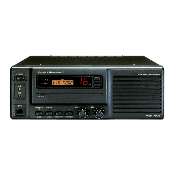
Desktop repeater, uhf
Hide thumbs
Also See for VXR-7000:
- Service manual (134 pages) ,
- Operating manual (44 pages) ,
- Alignment manual (4 pages)
Table of Contents
Advertisement
Desktop Repeater
VXR-7000
Service Manual
Introduction
This manual provides technical information necessary for servicing the VXR-7000 FM Land Mobile Repeater.
Servicing this equipment requires expertise in handling surface-mount chip components. Attempts by non-qualified
persons to service this equipment may result in permanent damage not covered by the warranty, and may be illegal in
some countries.
Two PCB layout diagrams are provided for each double-sided circuit board in the repeater. Each side of is referred to
by the type of the majority of components installed on that side ("leaded" or "chip-only"). In most cases one side has only
chip components, and the other has either a mixture of both chip and leaded components (trimmers, coils, electrolytic
capacitors, ICs, etc.), or leaded components only.
While we believe the technical information in this manual to be correct, VERTEX STANDARD assumes no liability
for damage that may occur as a result of typographical or other errors that may be present. Your cooperation in pointing
out any inconsistencies in the technical information would be appreciated.
After Lot. 78 of this transceiver is assembled using Pb (lead) free solder, based on the RoHS specification.
Only lead-free solder (Alloy Composition: Sn-3.0Ag-0.5Cu) should be used for repairs performed on this apparatus. The
solder stated above utilizes the alloy composition required for compliance with the lead-free specification, and any solder with
the above alloy composition may be used.
Operating Manual Reprint .......................... 2
CE27 Programming Software Instruction ............10
Specifications ............................................... 16
Block Diagram ............................................. 21
Interconnection Diagram........................... 24
Circuit Description .................................... 25
Alignment ..................................................... 28
Board Unit (Schematics, Layouts & Parts)
PA Unit (Lot.1-61) .................................................. 33
VXR-7000 UHF Service Manual
(UHF)
Important Note
Contents
Vertex Standard LMR, Inc.
© 2015 Vertex Standard LMR, Inc.
E136890N
PA-2 Unit (Lot.62-) ................................................. 41
TX Unit (Lot.1-59) .................................................. 49
TX-2 Unit (Lot.60-) ................................................. 57
RX Unit (Lot.1-59) .................................................. 67
RX-2 Unit (Lot.60-) ................................................. 77
CNTL Unit .............................................................. 87
Display Unit .......................................................... 105
Key Unit ................................................................ 113
Filter Unit (50W Type) ........................................ 123
Filter-2 Unit (25W Type) ..................................... 129
SW Unit (25W Type) ............................................ 135
VR Unit .................................................................. 137
SQL Unit ................................................................ 139
PS Unit ................................................................... 141
1
Advertisement
Table of Contents

Related Manuals for Vertex Standard VXR-7000


Summary of Contents for Vertex Standard VXR-7000
-
Page 1: Table Of Contents
ICs, etc.), or leaded components only. While we believe the technical information in this manual to be correct, VERTEX STANDARD assumes no liability for damage that may occur as a result of typographical or other errors that may be present. Your cooperation in pointing out any inconsistencies in the technical information would be appreciated. -
Page 2: Operating Manual Reprint
High/Low power selection, as determined by your “REPEATER” mode and the “BASE” transceiver Vertex Standard dealer. The LED above it glows green mode. When the “REPEATER” mode is selected, the when this function is activated. For further details, con- LED above it glows green. - Page 3 This DB-25 connector provides a data interface be- When operating from AC mains, a small trickle cur- tween the microprocessor in the VXR-7000 and pe- rent is present at these terminals to maintain battery ripheral devices (such as the VX-TRUNK Unit).
- Page 4 Operating Manual Reprint Pin 7: GND ACC Connector Port Chassis ground for all logic levels and power supply The VXR-7000 repeater is provided with a 25-pin DB- return. 25F female connector for interconnections to accesso- Pin 8: RSSI [Analog Output] ries.
- Page 5 This digital data sig- nal is injected after transmitter splatter filter stage. Pin 16 Pin 17 Pin 18 Pin 19 Channel ( D3 ) ( D2 ) ( D1 ) ( D0 ) VXR-7000 UHF Service Manual...
- Page 6 Operating Manual Reprint LINE Interface Port Installation The VXR-7000 is provided with an 8-pin modular jack Antenna Considerations for line interfacing applications. A Western Electric ® modu- Repeater operation without a duplexer requires that two lar-type RJ45 plug should be used to connect to this jack.
- Page 7 Never reapply AC power to the repeater with a discharged battery connected, as the DC startup current can dam- age the repeater and battery. While operating from a battery or DC supply, the repeater requires approximately 7 amperes at 12 Volts during trans- mit. VXR-7000 UHF Service Manual...
- Page 8 Important!: If you change the AC voltage range, you must move the heatsink from the Switching Regulator Unit. also change the AC fuse on the FILTER Unit. Do not re- place with a slow-blow type fuse. FILTER Unit Switching Regulator Unit Figure 2 Figure 1 VXR-7000 UHF Service Manual...
- Page 9 Operating Manual Reprint Switching Regulator Unit Figure 4 Figure 3 VXR-7000 UHF Service Manual...
-
Page 10: Ce27 Programming Software Instruction
Before creating the programming data for your Before connecting the VXR-7000 for programming, VXR-7000 via the CE27 programming software, turn off both the computer and the VXR-7000. Now con- upload the current factory hardware environ- nect the FIF-10A (or FIF-12) + CT-104A USB Program- ment data from the VXR-7000, using the [F5] ming Interface to the computer’s USB port and the VXR-... - Page 11 This number (1 - 16) is used to identify the channel. Chan- This function selects the channel spacing environment in nel numbers occur in sequence, and their order can not be which the VXR-7000 operates. changed. W (Wide) = 25 kHz Channel Spacing, ±5 kHz De- viation.
- Page 12 When this parameter is set to “on,” this function caus- Double-click the left mouse button on the “Multi Tone es the VXR-7000 to send out a “blip” on the portable/ Enable” to toggle the Multi Tone Operation between se- mobile radio is frequency each time the portable radio is lections “yes (“...
- Page 13 This parameter selects the desired power output from the The inhibit time is determined via dealer programing. VXR-7000 on the current channel. The available values are HIGH and LOW. Double-click the left mouse button to select “Hi” or “Lo.”...
- Page 14 Operating Manual Reprint 1. Connect the VXR-7000’s TX antenna port to a watt- meter and dummy load (the duplexer must not be con- Duplexer Installation nected at this point). Connect any Vertex Standard microphone to the MIC jack, and place the BASE/ Important Notes! REPEATER switch in the “BASE”...
- Page 15 6. Connect the optional Antenna Cable CT-68 between the TX antenna jack of the repeater and ANT (center) jack of the duplexer. Top Side Bottom Side Figure 1 Bottom Side Bottom Side Figure 2 Figure 3 Figure 4 VXR-7000 UHF Service Manual...
-
Page 16: Specifications
±5.0 kHz (25 kHz spacing), ±2.5 kHz (12.5 kHz spacing) Maximum Deviation: 16K0G3E/8K50G3E Modulation Type: Less than 2.5 % @ 1 kHz Audio Distortion: < –36 dBm @ <1 GHz, <–30 dBm @ >1 GHz Spurious Emissions: Specifications subject to change without notice or obligation. VXR-7000 UHF Service Manual... -
Page 17: Exploded View & Miscellaneous Parts
TOOTHED LOCK WASHER OW4NI CONNECTOR Ⓔ M4090066 Non-designated parts are available only as part of a designated assembly. RA0181200 SPEAKER HOLDER (MJ) SQL Unit RA0065800 RUBBER HOLDER (SP) Ⓘ VOL Unit RA0180700 RA0180500 PUSH KNOB (4pcs) VOLUME KNOB VXR-7000 UHF Service Manual... - Page 18 TOOTHED LOCK WASHER OW4NI CONNECTOR RA0181200 SPEAKER SQL Unit HOLDER (MJ) Non-designated parts are available only as part of a designated assembly. RA0065800 RUBBER HOLDER (SP) Ⓘ VOL Unit RA0180500 RA0180700 VOLUME KNOB PUSH KNOB (4pcs) VXR-7000 UHF Service Manual...
- Page 19 Heat sink PA-2 ASSY CS1861001 for 25 W CS1861002 for 50 W Main Heat Sink Plate (No Part # and impossible to purchase this part only) Rubber Spacer Heat Sink Plate Screws M2.6X5 RA0766400 RA0766900 U32450001 VXR-7000 UHF Service Manual...
- Page 20 Non-designated parts are available only as part of a designated assembly. FOOT (4pcs) P1091073 Ⓔ M4090066 CONNECTOR RA0181200 SPEAKER SQL Unit HOLDER (MJ) RA0065800 RUBBER HOLDER (SP) Ⓘ VOL Unit RA0180500 RA0180700 VOLUME KNOB PUSH KNOB (4pcs) VXR-7000 UHF Service Manual...
-
Page 21: Block Diagram
Block Diagram VXR-7000 UHF Service Manual... - Page 22 Block Diagram VXR-7000 UHF Service Manual...
- Page 23 Block Diagram VXR-7000 UHF Service Manual...
-
Page 24: Interconnection Diagram
Interconnection Diagram VXR-7000 UHF Service Manual... -
Page 25: Circuit Description
When no carrier is received, noise at the output of the ity to compensate for audio level variations, then passes audio detector stage of Q3012 is amplified by Q3015 through audio amplifier Q4014-1 (NJM2902), audio (2SC4116GR), and then rectified by D3015 (MA143) VXR-7000 UHF Service Manual... - Page 26 (derived from the RX VCO) and that derived from the crystal are applied to the phase detector section of the PLL IC Q3001, which produces a pulsed output with pulse duration depending on the phase difference between the VXR-7000 UHF Service Manual...
- Page 27 MIC jack via a VPL-1 programming cable. The output from the Main CPU Q4012, contains serial control data used for REPEATER/BASE mode control, as well as TX and RX PLL data. Crystal X4001 oscillates VXR-7000 UHF Service Manual...
-
Page 28: Alignment
Alignment Required Test Equipment The VXR-7000 is carefully aligned at the factory for RF Signal Generator with calibrated output level at the specified performance across the entire operating fre- quency range. Realignment should therefore not be nec- 1,000 MHz ... - Page 29 0 (00h) ~ 255 (FFh) Alignment Setup Maximum Deviation 0 (00h) ~ 255 (FFh) CTCSS Deviation 0 (00h) ~ 255 (FFh) DCS Deviation 0 (00h) ~ 255 (FFh) VCV Check Point TC2001 TX Unit Alignment Points VXR-7000 UHF Service Manual...
- Page 30 Select the Center channel, adjust TC3001 (on the RX Unit), if necessary, so that the frequency counter reading is within ±100 Hz of the programmed Cen- ter channel frequency. J3001 TC3001 VCV Check Point RX Unit Alignment Points VXR-7000 UHF Service Manual...
- Page 31 1 kHz. Key the repeater, and adjust VR4003 (on the CNTL Unit) so that the deviation meter reading (TX devia- tion) is 3.0 kHz (±0.1 kHz) deviation. S4002 VR4003 VR4001 S4001 VR4002 CNTL Unit Alignment Points VXR-7000 UHF Service Manual...
- Page 32 Note: VXR-7000 UHF Service Manual...
-
Page 33: Pa Unit (Lot.1-61)
RESISTOR VALUES ARE IN . 1/16W ; CAPACITOR VALUES ARE IN μF. 50V ; (T) CAPACITOR VALUES ARE TANTALUM ; ELECTOROLYTIC CAPACITORS ARE IN μF. 16V ; INDUCTOR VALUES ARE IN H ; COIL VALUES ARE IN H ; UNLESS OTHERWISE NOTED. VXR-7000 UHF Service Manual... -
Page 34: Vxr-7000 Uhf Service Manual
RESISTOR VALUES ARE IN . 1/16W ; CAPACITOR VALUES ARE IN μF. 50V ; (T) CAPACITOR VALUES ARE TANTALUM ; ELECTOROLYTIC CAPACITORS ARE IN μF. 16V ; INDUCTOR VALUES ARE IN H ; COIL VALUES ARE IN H ; UNLESS OTHERWISE NOTED. VXR-7000 UHF Service Manual... -
Page 35: Vxr-7000 Uhf Service Manual
PF0341A (Ver. A) (Q1502) TA75S01F (SA) NJM78L09UA (8H) (Q1509) (Q1508) UN5213 (8C) 2SB1122S (BE) (Q1506) (Q1503, 1505) Side A 2SC3357 (RK) 2SC4116GR (LG) (Q1501) (Q1504) 1SS319 (A4) MA143 (MC) (D1503, 1504) (D1502) RN739F (5F) (D1501) Side B VXR-7000 UHF Service Manual... -
Page 36: Vxr-7000 Uhf Service Manual
PA Unit (Lot. 1-61: Replaced by PA-2 Unit) Note VXR-7000 UHF Service Manual... -
Page 37: Vxr-7000 Uhf Service Manual
C 1542 FILM CAP. 27pF 500V UC232H0270J-T K33279023 VERS. A C 1542 FILM CAP. 18pF 500V UC232H0180J-T K33279029 VERS. D C 1543 FILM CAP. 500V UC232H0060D-T K33279045 1-17 C 1543 FILM CAP. 500V UC232H0040D-T K33279044 VERS. A VXR-7000 UHF Service Manual... -
Page 38: Vxr-7000 Uhf Service Manual
VERS. D, EIA (CE) FB1505 CORE 3A4-TMEC-TR16A L9190126 VERS. A, EIA (CE) FB1505 CORE 3A4-TMEC-TR16A L9190126 VERS. D, EIA (CE) FB1506 CORE 3A4-TMEC-TR16A L9190126 VERS. A, EIA (CE) FB1506 CORE 3A4-TMEC-TR16A L9190126 VERS. D, EIA (CE) VXR-7000 UHF Service Manual... -
Page 39: Vxr-7000 Uhf Service Manual
R 1525 CHIP RES. 6.8k 1/16W RMC1/16 682JATP J24185682 VERS. A, EIA (CE) R 1525 CHIP RES. 1/16W RMC1/16 153JATP J24185153 VERS. D R 1525 CHIP RES. 1/16W RMC1/16 153JATP J24185153 VERS. D, Ex. EIA (CE) 19- VXR-7000 UHF Service Manual... -
Page 40: Vxr-7000 Uhf Service Manual
VERS. A, EIA (CE) LEAF SPRING R0140031 VERS. A, EIA (CE) LEAF SPRING R0140031 VERS. A, EIA (CE) LEAF SPRING R0140031 VERS. D, EIA (CE) LEAF SPRING R0140031 VERS. A, EIA (CE) LEAF SPRING R0140031 VERS. D, EIA (CE) VXR-7000 UHF Service Manual... -
Page 41: Unit (Lot.62-)
RESISTOR VALUES ARE IN . 1/16W ; CAPACITOR VALUES ARE IN μF. 50V ; (T) CAPACITOR VALUES ARE TANTALUM ; ELECTOROLYTIC CAPACITORS ARE IN μF. 16V ; INDUCTOR VALUES ARE IN H ; COIL VALUES ARE IN H ; UNLESS OTHERWISE NOTED. VXR-7000 UHF Service Manual... - Page 42 PA-2 Unit (Lot. 62~) Note VXR-7000 UHF Service Manual...
- Page 43 S-AU83L (25 W Version TYP BS1: Lot 71-) (Q7005) (Q7006) (Q7008) RA30H4452M (25 W Version TYP D: Lot 71-) S-AU93 (50 W Version) (Q7007) LM2904PWR 2SC5019 (1W) FMG2 (26) HSM88AS (C1) (Q7009) (Q7008) (Q7004) (D7003, 7004) 2SC5415 (EA) RN739F (5F) (Q7001) (D7001, 7005) VXR-7000 UHF Service Manual...
- Page 44 PA-2 Unit (Lot. 62~) Parts Layout (Side B) VXR-7000 UHF Service Manual...
- Page 45 FILM CAP. 500V UC232H0010D-T K33279036 25W VERS. D C 7043 FILM CAP. 500V UC232H0010D-T K33279036 50W VERS. A C 7043 FILM CAP. 500V UC232H0020D-T K33279043 50W VERS. D C 7044 CHIP CAP. 100pF 500V GRM42-6CH101J500PT K22271237 VXR-7000 UHF Service Manual...
- Page 46 M.RFC FBA03VA450AB-00 L1190389 1-63 FB7003 M.RFC FBA03VA450AB-00 L1190389 64-70 FB7004 CORE 3A4-TMEC-TR16A L9190126 1-63 FB7004 CORE 3A4-TMEC-TR16A L9190126 FB7005 CORE 3A4-TMEC-TR16A L9190126 1-63 FB7005 CORE 3A4-TMEC-TR16A L9190126 FB7006 CORE 3A4-TMEC-TR16A L9190126 1-63 FB7006 CORE 3A4-TMEC-TR16A L9190126 VXR-7000 UHF Service Manual...
- Page 47 J24185821 R 7016 CHIP RES. 1/16W RMC1/16 5R6JATP J24185569 R 7017 CHIP RES. 1/16W RMC1/16 821JATP J24185821 R 7018 CHIP RES. 3.3k 1/16W RMC1/16 332JATP J24185332 1-158 R 7019 CHIP RES. 1/10W RMC1/10T 121J J24205121 1-70 VXR-7000 UHF Service Manual...
- Page 48 RA069650A 25W VERS. D GROUND PLATE RA069650A 25W VERS. BS1 71- GROUND PLATE RA069650A 50W VERS. D 71-158 TERMINAL B4 AG M3 Q6000114 50W VERS. A 157- TERMINAL B4 AG M3 Q6000114 50W VERS. D 159- VXR-7000 UHF Service Manual...
-
Page 49: Tx Unit (Lot.1-59)
RESISTOR VALUES ARE IN . 1/16W ; CAPACITOR VALUES ARE IN μF. 50V ; (T) CAPACITOR VALUES ARE TANTALUM ; ELECTOROLYTIC CAPACITORS ARE IN μF. 16V ; INDUCTOR VALUES ARE IN H ; COIL VALUES ARE IN H ; UNLESS OTHERWISE NOTED. VXR-7000 UHF Service Manual... - Page 50 RESISTOR VALUES ARE IN . 1/16W ; CAPACITOR VALUES ARE IN μF. 50V ; (T) CAPACITOR VALUES ARE TANTALUM ; ELECTOROLYTIC CAPACITORS ARE IN μF. 16V ; INDUCTOR VALUES ARE IN H ; COIL VALUES ARE IN H ; UNLESS OTHERWISE NOTED. VXR-7000 UHF Service Manual...
- Page 51 (Q2011, 2019) (Q2014, 2015) (Q2004) (Q2002, 2006, 2009) 2SC5226 (R22) (Q2008) 2SA1586Y (SY) 2SC3357 (RK) RN739F (5F) 2SA1179 (M6) 2SD1664 (DA) MA143 (MC) (Q2003) (Q2010) (D2009, 2010) (D2011, 2012) (Q2013, 2016) (Q2021, 2022) 2SA1586Y (SY) (Q2007) VXR-7000 UHF Service Manual...
- Page 52 TX Unit (Lot.1-59: Replaced by TX-2 Unit) Note VXR-7000 UHF Service Manual...
- Page 53 K22174235 C 2051 CHIP CAP. 100pF GRM1882C1H101JA01D K22174235 C 2052 CHIP CAP. 0.001uF GRM188B11H102KA01D K22174821 C 2053 CHIP CAP. 100pF GRM1882C1H101JA01D K22174235 C 2054 CHIP CAP. 100pF GRM1882C1H101JA01D K22174235 C 2055 CHIP CAP. 470pF GRM1882C1H471JA01D K22174249 VXR-7000 UHF Service Manual...
- Page 54 Q 2003 TRANSISTOR 2SA1586Y(TE85R.F) G3115867Y Q 2004 TRANSISTOR UN5215-(TX) G3070193 Q 2005 2SK508-T2B K52 A G3805087B Q 2006 TRANSISTOR 2SC4116GR(TE85R.F) G3341167G Q 2007 TRANSISTOR 2SA1586Y(TE85R.F) G3115867Y Q 2008 TRANSISTOR 2SC5226-4/5-TL G3352268Z Q 2009 TRANSISTOR 2SC4116GR(TE85R.F) G3341167G VXR-7000 UHF Service Manual...
- Page 55 1/16W RMC1/16 331JATP J24185331 R 2050 CHIP RES. 1/16W RMC1/16 180JATP J24185180 R 2051 CHIP RES. 1/16W RMC1/16 000JATP J24185000 R 2052 CHIP RES. 1/16W RMC1/16 103JATP J24185103 R 2053 CHIP RES. 1/16W RMC1/16 331JATP J24185331 VXR-7000 UHF Service Manual...
- Page 56 THERMISTOR NT732ATD2.0K K G9090079 X 2001 XTAL TOP-B 14.4MHz 14.4MHZ H0103221 SHIELD CASE RA0014300 SHIELD CASE R0151950 LEAF SPRING R0140031 LEAF SPRING R0140031 VERS. A, EIA (CE) 31- GROUND PLATE RA0338600 VERS. A, EIA (CE) 31- VXR-7000 UHF Service Manual...
-
Page 57: Unit (Lot.60-)
RESISTOR VALUES ARE IN . 1/16W ; CAPACITOR VALUES ARE IN μF. 50V ; (T) CAPACITOR VALUES ARE TANTALUM ; ELECTOROLYTIC CAPACITORS ARE IN μF. 16V ; INDUCTOR VALUES ARE IN H ; COIL VALUES ARE IN H ; UNLESS OTHERWISE NOTED. VXR-7000 UHF Service Manual... - Page 58 TX-2 Unit (Lot. 60-) Note VXR-7000 UHF Service Manual...
- Page 59 (Q2011, 2019) 2SA1586Y (SY) 2SC3357 (RK) 2SC4116GR (LG) RN739F (5F) 2SA1179 (M6) 2SC4116GR (LG) 2SD1664 (DA) MA143 (MC) (Q2003) (Q2010) (Q2002) (D2009, 2010) (Q2013, 2016) (Q2006, 2009) (Q2021, 2022) (D2011, 2012) 2SA1586Y (SY) 2SC5226 (R22) (Q2007) (Q2008) VXR-7000 UHF Service Manual...
- Page 60 TX-2 Unit (Lot. 60-) Note VXR-7000 UHF Service Manual...
- Page 61 CHIP CAP. GRM1882C1H5R0CZ01D K22174206 C 2044 CHIP TA.CAP. 10uF TEESVB21C106M8R K78120025 C 2045 CHIP CAP. GRM1882C1H5R0CZ01D K22174206 C 2046 CHIP TA.CAP. 10uF TEESVB21C106M8R K78120025 C 2047 CHIP CAP. 0.001uF GRM188B11H102KA01D K22174821 C 2048 CHIP CAP. GRM1882C1H6R0DZ01D K22174207 VXR-7000 UHF Service Manual...
- Page 62 VERS. BS1 L 2004 M.RFC 0.082uH HK1608 82NJ-T L1690527 VERS. D L 2005 M.RFC 0.082uH HK1608 82NJ-T L1690527 L 2006 CHIP COIL 0.022uH C2520C-22NK L1690536 L 2007 M.RFC 0.022uH HK1608 22NJ-T L1690520 Q 2001 MB15A02PFV1-G-BND-EFE1 G1092541 VXR-7000 UHF Service Manual...
- Page 63 RMC1/16 180JATP J24185180 R 2036 CHIP RES. 1/16W RMC1/16 180JATP J24185180 R 2037 CHIP RES. 1/16W RMC1/16 180JATP J24185180 R 2038 CHIP RES. 2.2k 1/16W RMC1/16 222JATP J24185222 R 2039 CHIP RES. 1/16W RMC1/16 103JATP J24185103 VXR-7000 UHF Service Manual...
- Page 64 1/16W RMC1/16 332JATP J24185332 R 2090 CHIP RES. 3.3k 1/16W RMC1/16 332JATP J24185332 R 2093 CHIP RES. 1/16W RMC1/16 000JATP J24185000 R 2094 CHIP RES. 1/16W RMC1/16 103JATP J24185103 R 2095 CHIP RES. RMC1 221JTE J24305221 VXR-7000 UHF Service Manual...
- Page 65 RA0338600 VERS. BS1 (EIA/CE) GROUND PLATE RA0338600 VERS. D (EIA/CE) GROUND PLATE RA0338600 VERS. BS1 (ex. EIA/CE) 71- GROUND PLATE RA0338600 VERS. A (EIA/CE) GROUND PLATE RA0338600 VERS. BS1 (EIA/CE) GROUND PLATE RA0338600 VERS. D (EIA/CE) VXR-7000 UHF Service Manual...
- Page 66 TX-2 Unit (Lot.60-) Note VXR-7000 UHF Service Manual...
-
Page 67: Rx Unit (Lot.1-59)
RESISTOR VALUES ARE IN . 1/16W ; CAPACITOR VALUES ARE IN μF. 50V ; (T) CAPACITOR VALUES ARE TANTALUM ; ELECTOROLYTIC CAPACITORS ARE IN μF. 16V ; INDUCTOR VALUES ARE IN H ; COIL VALUES ARE IN H ; UNLESS OTHERWISE NOTED. VXR-7000 UHF Service Manual... - Page 68 RESISTOR VALUES ARE IN . 1/16W ; CAPACITOR VALUES ARE IN μF. 50V ; (T) CAPACITOR VALUES ARE TANTALUM ; ELECTOROLYTIC CAPACITORS ARE IN μF. 16V ; INDUCTOR VALUES ARE IN H ; COIL VALUES ARE IN H ; UNLESS OTHERWISE NOTED. VXR-7000 UHF Service Manual...
- Page 69 RN739F (5F) (D3003) XN1213 (9L) 2SA1586Y (SY) 2SC2812 (L6) 2SB1122S (BE) (Q3016, 3020, 3022) (Q3007) (Q3013) (Q3018) 2SC4116GR (LG) (Q3006, 3010) HZM5.6NB2 (562) MA142WK (MU) MA143 (MC) 1SS302 (C3) (D3014) (D3012, 3013) (D3017, 3018) (D3001) Side B VXR-7000 UHF Service Manual...
- Page 70 RX Unit (Lot.1-59: Replaced by RX-2 Unit) Note VXR-7000 UHF Service Manual...
- Page 71 CHIP CAP. 0.1uF GRM188B11C104KA01D K22124805 C 3047 CHIP CAP. 0.1uF GRM188B11C104KA01D K22124805 C 3048 CHIP CAP. GRM1882C1H4R0CZ01D K22174205 C 3049 CHIP CAP. GRM1882C1H7R0DZ01D K22174208 C 3052 CHIP CAP. GRM1882C1H4R0CZ01D K22174205 C 3053 CHIP CAP. 15pF GRM1882C1H150JA01D K22174215 VXR-7000 UHF Service Manual...
- Page 72 K22174821 C 3106 CHIP CAP. 0.1uF GRM188B11C104KA01D K22124805 C 3107 CHIP CAP. 0.001uF GRM188B11H102KA01D K22174821 C 3108 CHIP CAP. 0.01uF GRM39B103M25PT K22144802 C 3109 CHIP CAP. 0.01uF GRM39B103M25PT K22144802 C 3110 CHIP CAP. 82pF GRM1882C1H820JA01D K22174233 VXR-7000 UHF Service Manual...
- Page 73 DIODE HVU350 TRF-E G2070380 D 3009 DIODE HVU350 TRF-E G2070380 D 3010 DIODE HVU350 TRF-E G2070380 D 3011 GN2011-Q(TX) G1092183 D 3012 DIODE MA142WK-(TX) G2070534 D 3013 DIODE MA142WK-(TX) G2070534 D 3014 DIODE HZM5.6NB2 TR-E G2070722 VXR-7000 UHF Service Manual...
- Page 74 Q 3007 TRANSISTOR 2SA1586Y(TE85R.F) G3115867Y Q 3008 2SK508-T2B K52 A G3805087B Q 3009 TRANSISTOR 2SC5226-4/5-TL G3352268Z Q 3010 TRANSISTOR 2SC4116GR(TE85R.F) G3341167G Q 3011 TRANSISTOR 2SC3357-T2 RF G3333577F Q 3012 TA31136FNG(EL) G1091605 Q 3013 TRANSISTOR 2SC2812L6-TA G3328127F VXR-7000 UHF Service Manual...
- Page 75 RMC1/16 154JATP J24185154 R 3062 CHIP RES. 1/16W RMC1/16 103JATP J24185103 R 3063 CHIP RES. 1.8k 1/16W RMC1/16 182JATP J24185182 R 3064 CHIP RES. 1/16W RMC1/16 223JATP J24185223 R 3065 CHIP RES. 1/10W RMC1/10T 331J J24205331 VXR-7000 UHF Service Manual...
- Page 76 SHIELD CASE CASE-S7GDH L9190016 SHIELD CASE CASE-S7GDH L9190016 SHIELD CASE CASE-S7GDH L9190016 VERS. A, EIA (CE) SHIELD CASE RA0014300 SHIELD CASE R0151950 SHIELD CASE RA0014200 NYLON CLAMP PLT-1M BK-1 S3000022 LEAF SPRING R0140031 LEAF SPRING R0140031 VXR-7000 UHF Service Manual...
-
Page 77: Unit (Lot.60-)
RESISTOR VALUES ARE IN . 1/16W ; CAPACITOR VALUES ARE IN μF. 50V ; (T) CAPACITOR VALUES ARE TANTALUM ; ELECTOROLYTIC CAPACITORS ARE IN μF. 16V ; INDUCTOR VALUES ARE IN H ; COIL VALUES ARE IN H ; UNLESS OTHERWISE NOTED. VXR-7000 UHF Service Manual... - Page 78 RX-2 Unit (Lot. 60-) Note VXR-7000 UHF Service Manual...
- Page 79 GN2011-Q (4W) (Q3004) (D3011) (D3015, 3016) RN739F (5F) (D3003) Side A 2SB1122S (BE) 2SC2812 (L6) XN1213 (9L) (Q3018) (Q3013) (Q3016, 3020, 3022) 2SC4116GR (LG) (Q3010) 1SS302 (C3) HZM5.6NB2 (562) MA142WK (MU) (D3001) (D3014) (D3012, 3013) Side B VXR-7000 UHF Service Manual...
- Page 80 RX-2 Unit (Lot. 60-) Note VXR-7000 UHF Service Manual...
- Page 81 GRM1882C1H7R0DZ01D K22174208 C 3043 CHIP CAP. 0.1uF GRM188B11C104KA01D K22124805 C 3044 CHIP CAP. 12pF GRM1882C1H120JA01D K22174213 VERS. A C 3044 CHIP CAP. 12pF GRM1882C1H120JA01D K22174213 VERS. BS1 C 3044 CHIP CAP. 10pF GRM1882C1H100JA01D K22174211 VERS. D VXR-7000 UHF Service Manual...
- Page 82 K22174223 C 3099 CHIP CAP. 0.001uF GRM188B11H102KA01D K22174821 C 3100 CHIP CAP. 39pF GRM1882C1H390JA01D K22174225 C 3102 CHIP CAP. 0.1uF GRM188B11C104KA01D K22124805 C 3103 CHIP CAP. 0.1uF GRM188B11C104KA01D K22124805 C 3104 CHIP CAP. 0.01uF GRM39B103M25PT K22144802 VXR-7000 UHF Service Manual...
- Page 83 CERAMIC FILTER CFWLB455KGFA-B0 H3900399 CF3002 CERAMIC FILTER CFWLB455KFFA-B0 H3900395 D 3001 DIODE 1SS302(TE85R.F) G2070088 D 3002 DIODE RD6.8UMB2-T1B G2070438 D 3003 DIODE RN739F T106 G2070626 D 3004 DIODE HVU350 TRF-E G2070380 D 3005 DIODE HVU350 TRF-E G2070380 VXR-7000 UHF Service Manual...
- Page 84 M.RFC 4.7uH LK1608 4R7K-T L1690688 Q 3001 MB15A02PFV1-G-BND-EFE1 G1092541 Q 3002 TAR5S30(TE85L.F) G1093570 Q 3003 TRANSISTOR 2SA1586Y(TE85R.F) G3115867Y Q 3004 TRANSISTOR UN5215-(TX) G3070193 1-152 Q 3004 TRANSISTOR DRC5114T0L G3070444 153- Q 3005 TRANSISTOR 2SC3357-T2 RF G3333577F VXR-7000 UHF Service Manual...
- Page 85 RMC1/16 682JATP J24185682 R 3053 CHIP RES. 1/16W RMC1/16 333JATP J24185333 R 3054 CHIP RES. 1/16W RMC1/16 333JATP J24185333 R 3055 CHIP RES. 1/16W RMC1/16 181JATP J24185181 R 3056 CHIP RES. 1.2k 1/16W RMC1/16 122JATP J24185122 VXR-7000 UHF Service Manual...
- Page 86 CASE-S7GDH L9190016 VERS. BS1 (ex. EIA/CE) 62-184 SHIELD CASE KC-175 L9190207 VERS. BS1 (ex. EIA/CE) 185- SHIELD CASE RA0014300 SHIELD CASE R0151950 SHIELD CASE RA0014200 NYLON CLAMP PLT-1M BK-1 S3000022 LEAF SPRING R0140031 LEAF SPRING R0140031 VXR-7000 UHF Service Manual...
-
Page 87: Cntl Unit
RESISTOR VALUES ARE IN . 1/16W ; CAPACITOR VALUES ARE IN μF. 50V ; (T) CAPACITOR VALUES ARE TANTALUM ; ELECTOROLYTIC CAPACITORS ARE IN μF. 16V ; INDUCTOR VALUES ARE IN H ; COIL VALUES ARE IN H ; UNLESS OTHERWISE NOTED. VXR-7000 UHF Service Manual... - Page 88 RESISTOR VALUES ARE IN . 1/16W ; CAPACITOR VALUES ARE IN μF. 50V ; (T) CAPACITOR VALUES ARE TANTALUM ; ELECTOROLYTIC CAPACITORS ARE IN μF. 16V ; INDUCTOR VALUES ARE IN H ; COIL VALUES ARE IN H ; UNLESS OTHERWISE NOTED. VXR-7000 UHF Service Manual...
- Page 89 RESISTOR VALUES ARE IN . 1/16W ; CAPACITOR VALUES ARE IN μF. 50V ; (T) CAPACITOR VALUES ARE TANTALUM ; ELECTOROLYTIC CAPACITORS ARE IN μF. 16V ; INDUCTOR VALUES ARE IN H ; COIL VALUES ARE IN H ; UNLESS OTHERWISE NOTED. VXR-7000 UHF Service Manual...
- Page 90 CNTL Unit Note VXR-7000 UHF Service Manual...
- Page 91 (Q4039) DTC144EK (26) DTC323TK (H02) 2SC4116GR (LG) (Q4023, 4035, 4044) (Q4036, 4038) (Q4027) RH5VL45AA (D5) TLP181 2SA1586Y (SY) (Q4005) (Q4041, 4042) (Q4007) MA143 (MC) (D4036, 4037) DA204K (K) (D4006, 4009, 4012, 4016, 4019, 4020, 4022, 4023) VXR-7000 UHF Service Manual...
- Page 92 DTC144EK (26) DTC323TK (H02) (Q4026, 4037) (Q4006, 4009, (Q4003) 4010, 4011) 2SC4116GR (LG) (Q4013) DA204K (K) 1SS184 (B3) HZM7C (24) (D4001, 4002, 4003, (D4025, 4026) (D4008) 4004, 4005, 4017, 4018, 4021, 4024, 4040) HZM7.5NB2 (Lot. 41~) (D4008) VXR-7000 UHF Service Manual...
- Page 93 C 4055 CHIP CAP. 100pF GRM1882C1H101JA01D K22174235 1-18 C 4055 CHIP CAP. 220pF GRM1882C1H221JA01D K22174243 C 4056 CHIP CAP. 330pF GRM1882C1H331JA01D K22174253 C 4057 CHIP CAP. 0.1uF GRM188B11C104KA01D K22124805 C 4058 CHIP CAP. 330pF GRM1882C1H331JA01D K22174253 VXR-7000 UHF Service Manual...
- Page 94 GRM188B11C104KA01D K22124805 C 4122 CHIP CAP. 0.001uF GRM188B11H102KA01D K22174821 C 4124 CHIP TA.CAP. 1.5uF TEESVA1D155M8R K78130013 C 4125 CHIP CAP. 0.0015uF GRM188B11H152KA01D K22174811 C 4126 CHIP CAP. 0.1uF GRM188B11C104KA01D K22124805 C 4127 CHIP CAP. GRM21BB11A105KA01L K22100802 VXR-7000 UHF Service Manual...
- Page 95 K22124805 C 4193 CHIP TA.CAP. 0.22uF TEESVA1V224M8R K78160027 1-21 C 4193 CHIP TA.CAP. 0.1uF TEESVA1V104M8R K78160025 VERS. A C 4193 CHIP TA.CAP. 0.1uF TEESVA1V104M8R K78160025 VERS. BS1 C 4193 CHIP TA.CAP. 0.22uF TEESVA1V224M8R K78160027 VERS. D VXR-7000 UHF Service Manual...
- Page 96 GRM188B11H102KA01D K22174821 C 4254 CHIP CAP. 0.001uF GRM188B11H102KA01D K22174821 C 4255 CHIP CAP. 0.001uF GRM188B11H102KA01D K22174821 C 4256 CHIP CAP. 0.001uF GRM188B11H102KA01D K22174821 C 4257 CHIP CAP. 0.001uF GRM188B11H102KA01D K22174821 C 4258 AL.ELECTRO.CAP. 470uF RE3-16V471MG3# K40129066 VXR-7000 UHF Service Manual...
- Page 97 D 4030 SURGE ABSORBER ERZ-V07D121 Q9000604 D 4031 SURGE ABSORBER ERZ-V07D121 Q9000604 D 4032 SURGE ABSORBER ERZ-V07D121 Q9000604 D 4033 SURGE ABSORBER ERZ-V07D121 Q9000604 D 4034 SURGE ABSORBER ERZ-V07D121 Q9000604 D 4036 DIODE MA143-(TX) G2070536 1-185 VXR-7000 UHF Service Manual...
- Page 98 G1091679 Q 4034 NJM2902V-TE1 G1091679 Q 4035 TRANSISTOR DTC144EK T146 G3070033 Q 4036 TRANSISTOR DTC323TK T146 G3070042 Q 4037 TRANSISTOR DTC323TK T146 G3070042 Q 4038 TRANSISTOR DTC323TK T146 G3070042 Please contact Vertes Standard LMR, Inc. VXR-7000 UHF Service Manual...
- Page 99 RMC1/16 562JATP J24185562 R 4061 CHIP RES. 1/16W RMC1/16 393JATP J24185393 R 4062 CHIP RES. 4.7k 1/16W RMC1/16 472JATP J24185472 R 4063 CHIP RES. 470k 1/16W RMC1/16 474FTP J24183474 R 4064 CHIP RES. 1/16W RMC1/16 473JATP J24185473 VXR-7000 UHF Service Manual...
- Page 100 R 4132 CHIP RES. 100k 1/16W RMC1/16 104JATP J24185104 R 4133 CHIP RES. 6.8k 1/16W RMC1/16 682JATP J24185682 R 4134 CHIP RES. 150k 1/16W RMC1/16 154JATP J24185154 R 4135 CHIP RES. 150k 1/16W RMC1/16 154JATP J24185154 VXR-7000 UHF Service Manual...
- Page 101 J24185000 R 4197 CHIP RES. 1/16W RMC1/16 473JATP J24185473 R 4198 CHIP RES. 4.7k 1/16W RMC1/16 472JATP J24185472 R 4199 CHIP RES. 270k 1/16W RMC1/16 274JATP J24185274 R 4200 CHIP RES. 330k 1/16W RMC1/16 334JATP J24185334 VXR-7000 UHF Service Manual...
- Page 102 RMC1/16 104JATP J24185104 R 4267 CHIP RES. 1/10W RMC1/10T 2R7J J24205279 R 4268 CHIP RES. 100k 1/16W RMC1/16 104JATP J24185104 R 4269 CHIP RES. 3.3k 1/16W RMC1/16 332JATP J24185332 R 4270 CHIP RES. 1/16W RMC1/16 183JATP J24185183 VXR-7000 UHF Service Manual...
- Page 103 EVN-5ESX50B14 J51811103 1-130 VR4002 POT. EVM3VSX50B14 J51843103 131- VR4003 POT. EVN-5ESX50B14 J51811103 1-130 VR4003 POT. EVM3VSX50B14 J51843103 131- X 4001 XTAL HC-49/S3 16MHz 16.000MHZ H0103174 X 4002 XTAL HC-49/4H 4.194304MHz 4.194304MHZ H0103081 HEAT SINK SP143K S5000217 VXR-7000 UHF Service Manual...
- Page 104 CNTL Unit Note VXR-7000 UHF Service Manual...
-
Page 105: Display Unit
Display Unit Circuit Diagram (Lot. 1-107) VXR-7000 UHF Service Manual... - Page 106 XN1213 (9L) (Q5003) (Q5005) (Q5002, 5004) Side A DTC144EK (26) MA143 (MC) (Q5006, 5009) (D5003, 5005, 5006, 5007, 5008, 5009, 5010, 5011, 5014, 5015, 5016, 5017, 5018) LCD Display Segmentation Diagram Side B LCD Display Backplane Diagram VXR-7000 UHF Service Manual...
- Page 107 Display Unit Circuit Diagram (Lot. 108-) VXR-7000 UHF Service Manual...
- Page 108 5014, 5015, 5018, 5019, 5020, 5021) Side A 2SC4617 (BR) DAN217U (A7) (Q5004) (D5003, 5004, 5005, 5006, 5007, 5008, 5009, 5010, 5011, 5014, 5015, 5016, 5017, 5018) LCD Display Segmentation Diagram Side B LCD Display Backplane Diagram VXR-7000 UHF Service Manual...
- Page 109 DAN217U T106 G2071236 108- D 5017 DIODE MA143-(TX) G2070536 1-107 D 5017 DIODE DAN217U T106 G2071236 108- D 5018 DIODE MA143-(TX) G2070536 1-107 D 5018 DIODE DAN217U T106 G2071236 108- D 5019 DIODE MA729-(TX) G2070320 108-158 VXR-7000 UHF Service Manual...
- Page 110 1/4W RMC1/4 471JATP J24245471 R 5012 CHIP RES. 1/4W RMC1/4 471JATP J24245471 R 5013 CHIP RES. 1/16W RMC1/16 331JATP J24185331 R 5014 CHIP RES. 1/16W RMC1/16 103JATP J24185103 R 5015 CHIP RES. 1/16W RMC1/16 473JATP J24185473 VXR-7000 UHF Service Manual...
- Page 111 1-107 X 5001 XTAL U3B 7.3728MHz 7.3728MHZ H0103280 108- LCD HOLDER RA0014900 LIGHT GUIDE RA0013200 REFLECTOR SHEET RA0013500 DIFFUSER SHEET RA0013600 INTER CONNECTOR RA0013700 SPONGE RUBBER R7130200 LED SPACER LH-5-4 S6000237 LED SPACER LH-5-2 S6000235 1-107 VXR-7000 UHF Service Manual...
- Page 112 Display Unit Note VXR-7000 UHF Service Manual...
-
Page 113: Key Unit
RESISTOR VALUES ARE IN . 1/16W ; CAPACITOR VALUES ARE IN μF. 50V ; (T) CAPACITOR VALUES ARE TANTALUM ; ELECTOROLYTIC CAPACITORS ARE IN μF. 16V ; INDUCTOR VALUES ARE IN H ; COIL VALUES ARE IN H ; UNLESS OTHERWISE NOTED. VXR-7000 UHF Service Manual... - Page 114 RESISTOR VALUES ARE IN . 1/16W ; CAPACITOR VALUES ARE IN μF. 50V ; (T) CAPACITOR VALUES ARE TANTALUM ; ELECTOROLYTIC CAPACITORS ARE IN μF. 16V ; INDUCTOR VALUES ARE IN H ; COIL VALUES ARE IN H ; UNLESS OTHERWISE NOTED. VXR-7000 UHF Service Manual...
- Page 115 Key Unit Parts Layout (Lot. 1-107) BU4094BCFV (Q5503) Side A VXR-7000 UHF Service Manual...
- Page 116 Key Unit Parts Layout (Lot. 1-107) XN1213 (9L) (Q5502, 5504, 5505) DTC323TK (H02) (Q5501) DTC144EK (26) (Q5506) Side B VXR-7000 UHF Service Manual...
- Page 117 Key Unit Circuit Diagram (Lot. 108-) VXR-7000 UHF Service Manual...
- Page 118 Key Unit Parts Layout (Lot. 108-) BU4094BCFV (Q5503) Side A VXR-7000 UHF Service Manual...
- Page 119 Key Unit Parts Layout (Lot. 108-) XN1213 (9L) (Q5502, 5504, 5505) DTC323TK (H02) (Q5501) DTC144EK (26) (Q5506) Side B VXR-7000 UHF Service Manual...
- Page 120 Key Unit Note VXR-7000 UHF Service Manual...
- Page 121 S 5502 PUSH SWITCH SPPH110300 N4090142 S 5503 PUSH SWITCH SPPH110300 N4090142 S 5504 PUSH SWITCH SPPH110300 N4090142 S 5505 PUSH SWITCH SPPH110300 N4090142 LED SPACER LH-3-13 S6000350 LED SPACER LH-5-14 S6000387 LED SPACER LH-5-10 S6000243 VXR-7000 UHF Service Manual...
- Page 122 Key Unit Note VXR-7000 UHF Service Manual...
-
Page 123: Filter Unit (50W Type)
RESISTOR VALUES ARE IN . 1/16W ; CAPACITOR VALUES ARE IN μF. 50V ; (T) CAPACITOR VALUES ARE TANTALUM ; ELECTOROLYTIC CAPACITORS ARE IN μF. 16V ; INDUCTOR VALUES ARE IN H ; COIL VALUES ARE IN H ; UNLESS OTHERWISE NOTED. VXR-7000 UHF Service Manual... - Page 124 Filter Unit (50W Type) Note VXR-7000 UHF Service Manual...
- Page 125 Filter Unit (50W Type) Parts Layout (Side A) Side A NJM2904M IMX1 (X1) UN5213 (8C) XN1213 (9L) (Q6006) (Q6007) (Q6002) (Q6003) 2SA1179 (M6) 2SC2812 (L6) DAN202K (N) (Q6001) (Q6004, 6008) (D6002, 6005) VXR-7000 UHF Service Manual...
- Page 126 Filter Unit (50W Type) Parts Layout (Side B) Side B VXR-7000 UHF Service Manual...
- Page 127 RMC1/16 223JATP J24185223 R 6002 CHIP RES. 1/16W RMC1/16 223JATP J24185223 R 6003 CHIP RES. 220k 1/16W RMC1/16 224JATP J24185224 R 6004 CHIP RES. 1/16W RMC1/16 103JATP J24185103 R 6005 CHIP RES. 1/10W RMC1/10T 220J J24205220 VXR-7000 UHF Service Manual...
- Page 128 R 6033 CHIP RES. 100k 1/8W RMC1/8T 104J J24215104 RL6001 RELAY DC12V ACP131 DC12V M1190152 RL6003 RELAY DC12V ACP131 DC12V M1190152 T 6001 TOROIDAL COIL D12A RI16X8X8 L0022119 T 6003 TOROIDAL COIL D12A RI16X8X8 L0022119 RUBBER RA0217100 VXR-7000 UHF Service Manual...
-
Page 129: Filter-2 Unit (25W Type)
RESISTOR VALUES ARE IN . 1/16W ; CAPACITOR VALUES ARE IN μF. 50V ; (T) CAPACITOR VALUES ARE TANTALUM ; ELECTOROLYTIC CAPACITORS ARE IN μF. 16V ; INDUCTOR VALUES ARE IN H ; COIL VALUES ARE IN H ; UNLESS OTHERWISE NOTED. VXR-7000 UHF Service Manual... - Page 130 Filter-2 Unit (25W Type) Note VXR-7000 UHF Service Manual...
- Page 131 Filter-2 Unit (25W Type) Parts Layout (Side A) 2SA1179 (M6) 2SC2812 (L6) IMX1 (X1) UN5213 (8C) XN1213 (9L) DAN202K (N) (Q6001) (Q6004, 6008) (Q6007) (Q6002) (Q6003) (D6002, 6005) VXR-7000 UHF Service Manual...
- Page 132 Filter-2 Unit (25W Type) Parts Layout (Side B) VXR-7000 UHF Service Manual...
- Page 133 CHIP RES. 1/10W RMC1/10T 220J J24205220 R 6006 CHIP RES. 1/16W RMC1/16 223JATP J24185223 R 6007 CHIP RES. 1/16W RMC1/16 223JATP J24185223 R 6011 CHIP RES. 1/16W RMC1/16 223JATP J24185223 R 6012 CEMENT RES. ERF-5AK5R6 J30376569 1-118 VXR-7000 UHF Service Manual...
- Page 134 R 6031 CHIP RES. 1/16W RMC1/16 223JATP J24185223 RL6001 RELAY DC12V ACP131 DC12V M1190152 RL6003 RELAY DC12V ACP131 DC12V M1190152 T 6001 TOROIDAL COIL D12A RI16X8X8 L0022119 T 6003 TOROIDAL COIL D12A RI16X8X8 L0022119 RUBBER RA0217100 VXR-7000 UHF Service Manual...
-
Page 135: Sw Unit (25W Type)
A1367+ T9206794 JP6502 WIRE ASSY WHT 340 SRA/<7> T9318166 JP6503 WIRE ASSY BLK 330 SRA/<7> T9318167 JP6504 WIRE ASSY BRN 320 SRA/<7> T9318168 JP6505 WIRE ASSY GRA 330 SRA/<7> T9318169 S 6501 PUSH SWITCH SDDFE30100 N4090147 VXR-7000 UHF Service Manual... - Page 136 SW Unit (25W Type) Note VXR-7000 UHF Service Manual...
-
Page 137: Vr Unit
VR Unit Circuit Diagram (Lot. 1-107) Parts Layout (Lot. 1-107) Side A Side B VXR-7000 UHF Service Manual... - Page 138 Side A Side B Parts List REF. DESCRIPTION VALUE TOL. MFR’S DESIG VXSTD P/N VERS. LOT. SIDE LAYADR PCB with Components ( w/o JP5951 ) CS2349101 JP5951 WIRE ASSY T9206811 VR5901 POT. RK0971110 10KA (L=25) J60800241 VXR-7000 UHF Service Manual...
-
Page 139: Sql Unit
SQL Unit Circuit Diagram (Lot. 1-107) Parts Layout (Lot. 1-107) Side A Side B VXR-7000 UHF Service Manual... - Page 140 Parts Layout(Lot. 108-) Side A Side B Parts List REF. DESCRIPTION VALUE TOL. MFR’S DESIG VXSTD P/N VERS. LOT. SIDE LAYADR PCB with Components ( w/o JP5951 ) CS2320101 JP5951 WIRE ASSY T9206811 VR5951 POT. RK0971110 10KB(L=25) J60800242 VXR-7000 UHF Service Manual...
-
Page 141: Ps Unit
PS Unit Circuit Diagram VXR-7000 UHF Service Manual... - Page 142 PS Unit Parts Layout (Side A) S-80745AN (DI) NJM2904L (IC0001) (IC0021) 2SK1017 BT138D-600 (Q0002, 0003) (Q0001) 2PA1015 2SC4166Q (Q0021) (Q0004) 2PC1815 2SC3246 (Q0022) (Q0006, 0023) DTC114ESA (Q0005) VXR-7000 UHF Service Manual...
- Page 143 G3810170 Q 0004 TRANSISTOR 2SC4166-Q G3341660Q Q 0005 TRANSISTOR DTC114ESA G3090130 Q 0006 TRANSISTOR 2SC3246H G3332460H Q 0021 TRANSISTOR 2PA1015Y G3090131 Q 0022 TRANSISTOR 2PC1815Y G3090132 R 0001 CARBON FILM RES. 470k 1/2W RD50SS470K J J01279001 VXR-7000 UHF Service Manual...
- Page 144 FP2017A-614 S8001788 FITTING B FP2017A-615 S8001789 THERMAL CONDUCTER FP2017A-701 S8001790 THERMAL CONDUCTER FB419 S8001781 THERMAL CONDUCTER (4pcs) TC45A-(CP-T0-3P) S8001782 THERMAL CONDUCTER TC45A-(CP-T0-220) S8001783 FITTING (5pcs) FR336A S8001784 FITTING FR309A S8000030 SPACER (5pcs) S8001794 COVER FP2017A-612 S8001786 VXR-7000 UHF Service Manual...
- Page 145 VXR-7000 UHF Service Manual...
- Page 146 No portion of this manual may be reproduced without the permission of Vertex Standard LMR, Inc. Vertex Standard is a trademark of Vertex Standard LMR, Inc. All other trademarks are the property of their respective owners. ©2015 Vertex Standard LMR, Inc.