
Related Manuals for Sony HDVF-EL75


Summary of Contents for Sony HDVF-EL75
- Page 1 HD ELECTRONIC VIEWFINDER HDVF-EL75 OPERATION MANUAL [Japanese/English] 1st Edition...
- Page 5 • • • • • • • • • • • • • • • • • • • •...
- Page 6 • • • • • •...
- Page 7 • • • •...
- Page 10 • • •...
- Page 12 • •...
- Page 15 • • •...
- Page 16 CENTER UPPER RIGHT LOWER LEFT CENTER UPPER RIGHT LOWER LEFT • • •...
- Page 17 CENTER UPPER RIGHT LOWER LEFT...
- Page 18 • • • • • •...
- Page 19 • • M E N U F U N C T I O N A S S I G N W F M A K + A S S I G N M E N U A S S I G N M A G N I F I C A T I O N A S S I G N M A G...
- Page 21 • • [WFM] [PEAK+] [MONO] [MAG] [OFF] [OFF] [ITU709] [AUTO]...
- Page 22 [MODE1] [ON] [ON] [STD] [COLOR] [CENTER] [OFF]...
- Page 23 [OFF] [MODE1] [CENTER] [RIGHT] [AUTO] [OFF]...
- Page 24 • • [OFF] [RIGHT] [OFF] [LINE] [OFF] [50] [50] [ON] [ON] [ON] [ON] [ON]...
- Page 25 [ON] [ON] [ON] [OFF] PRESET [EXEC] [AUTO]...
- Page 28 For the customers in Europe The manufacturer of this product is Sony Corporation, 1- For the customers in Canada 7-1 Konan, Minato-ku, Tokyo, Japan. This Class A digital apparatus complies with Canadian The Authorized Representative for EMC and product ICES-003.
-
Page 29: Table Of Contents
Table of Contents Precautions Precautions ..........29 Handling the screen Overview ..........31 • The panel fitted to this unit is manufactured with high Functions of Parts and Controls ... 33 precision technology, giving a functioning pixel ratio of at least 99.99%. Thus a very small proportion of pixels Attaching to the Camera ...... - Page 30 On IBAC (Intelligent Brightness Ambient abrasives, or chemical wipe as these may damage the Control) screen. • This product has a built-in IBAC function to reduce • Use a blower to remove dust from the screen surface. burn-in. When a nearly still image is displayed for a specified period of time, the IBAC function is activated On installation automatically and the brightness of the screen...
-
Page 31: Overview
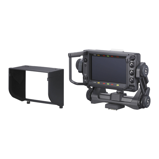
The matrix switching function brings to you broadcast standard (ITU-R BT.709/EBU/SMPTE-C) color space settings. Setting the matrix to OFF reproduces images in the The HDVF-EL75 HD Electronic Viewfinder is a 7.4-type original wide color space of OLED. color viewfinder for use with a Sony high-definition color camera. - Page 32 switches are provided for the left and right sides of the screen. These do not hinder the operator’s view, and they offer comfortable operation. Supplied indoor hood and optional VFH- 790 outdoor hood The indoor hood is supplied. The optional VFH-790 outdoor hood offers superior shading character.
-
Page 33: Functions Of Parts And Controls
Functions of Parts and Controls a ASSIGN. (assignable) switches f BATT (battery) indicator (red) Can be used to store frequently used functions. Lights up or flashes, to indicate the status of the battery The switches ASSIGN. L1 and ASSIGN. L2 are located attached to the camera as follows. - Page 34 When you connect the unit to peripheral device, use the An error message (see page 52) may be displayed at the supplied cable to prevent malfunction due to radiation same time. Turn off the power and contact your Sony noise. service representative.
-
Page 35: Attaching To The Camera
x Tilt friction adjustment knob Attaching to the Camera Adjusts the friction in the tilting mechanism. Turning the knob toward + increases the friction, and toward – decreases the friction. Attach the V-wedge shoe attachment to the camera and y MENU control attach the viewfinder to the V-wedge shoe attachment. - Page 36 When moving the viewfinder attached to Attach the supplied V-wedge shoe attachment to the camera using the supplied hexagonal wrench and the camera four hexagonal screws (4 ×12). Reset the viewfinder screen to the standard position and fix it in place by turning the tilt-lock knob and lift-lock knob toward the lock position.
-
Page 37: Turning On The Viewfinder
Turning on the Adjusting the Viewfinder Viewfinder Position When the camera is turned on and the POWER switch of Adjusting the Height and Tilting/ the viewfinder is set to ON, power is supplied to the Panning viewfinder. The image will be displayed several seconds after supplying power to the viewfinder. -
Page 38: Adjusting The Front-Back Position
Holding the handles, move the viewfinder to the • Depending on the shape of the connected camera, desired height and position. panning of the viewfinder may hinder use of the camera’s handle. If the position of the camera’s handle is fixed, adjust the position of the mounting wedge and/ Height adjustment or plates. -
Page 39: Adjusting The Screen
Slide or rotate the mounting wedge, lower plate, and/ Adjusting the Screen or upper plate as required, then tighten the screws. When the mounting wedge is slid forward: The viewfinder moves 15 mm (19/32 inches) toward Note the camera operator from the factory default position. -
Page 40: Attaching Accessories
Outdoor hood (optional) Attaching Accessories Attaching a Hood You can attach the optional VFH-790 outdoor hood in the same way as the supplied indoor hood. This section describes the procedure of attaching the indoor hood. To attach the hood, hook the hood to the groove the Coin screw (on both sides) viewfinder. -
Page 41: Using The Focus Assist Function
– direction: Using the Focus Assist Narrows the effective range Function + direction: Widens the effective range For details on menu operations, see “Using the Menu” on page 44. Adjust the amount of correction with the PEAKING PEAKING PLUS Function control. -
Page 42: Magnification Function
Turn the control clockwise to make the edges The edges of the object that coincides with the color sharper. detected in step 4 are sharpened within the area selected in step 3. Turn the control clockwise to make the edges To specify both color and area sharper. -
Page 43: Using The Level Adjust Function
MODE1: Standard magnified display Using the Level Adjust Function For details on menu operations, see “Using the Menu” on page 44. This function can be used to display the output level of the MODE2: Displays the original image at the bottom camera after adjustment inside the unit. -
Page 44: Using The Menu
item select mode. Press the MENU switch again to Using the Menu return to page select mode. Select menu items. Many of the viewfinder’s functions can be set by a menu With the mark positioned to the left of a menu item operation. - Page 45 The setting is entered and the menu returns to item select mode. If you press the MENU switch before pressing the MENU control, the setting returns to the value that was previously set and then the menu returns to item select mode.
-
Page 46: List Of Menu Items
List of Menu Items • “– – –” appears to the left of settings that cannot be Notes selected. • Some settings cannot be selected unless the previous menu item is set to “ON.” Page Menu Item Settings Function (default in [ FUNCTION ASSIGN. - Page 47 Page Menu Item Settings Function (default in [ FUNCTION OFF/[5]/15/30 For setting the time (minutes) after which the IBAC IBAC (Intelligent Brightness Ambient Control) function is activated. For the IBAC function, see “On IBAC (Intelligent Brightness Ambient Control)” on page 30. [MODE1]/MODE2 For selecting the operation mode upon pressing the PEAKING PLUS ASSIGN.
- Page 48 Page Menu Item Settings Function (default in [ –99 to [0] to 99 PEAKING SAT WIDTH For specifying the saturation range of which edge enhancement is to be performed. FREQUENCY L/[M]/MH/H For specifying the center frequency of edge enhancement signals. 1 to [2] to 3 RANGE For specifying the variability of edge enhancement level.
- Page 49 Page Menu Item Settings Function (default in [ WAVEFORM Displays a simplified input signal waveform as a sub display. The right illustration is an example of the waveform monitor when a color bar Selected signal is input. LINE Notes • Adjust the output level of camera under the LEVEL ADJUST menu before using the WAVEFORM Cursor...
- Page 50 Page Menu Item Settings Function (default in [ STATUS DISPLAY ASSIGN. L1 OFF/[ON] For selecting whether the changes in the status of the function assigned to the ASSIGN. L1 switch is displayed (ON) or not (OFF). ASSIGN. L2 OFF/[ON] For selecting whether the changes in the status of the function assigned to the ASSIGN.
- Page 51 If “ASSIGN. L1,” “ASSIGN. L2,” “ASSIGN. R1” or “ASSIGN. R2” in the FUNCTION menu is set to “MAG,” the magnified section changes in the sequence CENTER t UPPER t RIGHT t LOWER t LEFT when the respective switch is held down during a magnified display. A measuring instrument is required to adjust the color temperature.
-
Page 52: Error Message
Error Message Specifications General Display Description Power supply 10.5 V to 17.0 V DC (supplied by the camera) ERROR Failure in “COLOR DETECT” in Power consumption PEAKING PLUS mode, or “AUTO 19.5 W ADJUST” in LEVEL ADJUST menu Operating temperature BACKUP ERROR Checksums of the EEPROM backup –20°C to +45°C (–4°F to +113°F) - Page 53 Effective Format Horizontal Vertical Always verify that the unit is operating properly before scanning scanning scanning use. SONY WILL NOT BE LIABLE FOR DAMAGES lines frequency (kHz) frequency (Hz) OF ANY KIND INCLUDING, BUT NOT LIMITED 1080 23.98PsF 26.97 47.95...
- Page 55 The material contained in this manual consists of information that is the property of Sony Corporation and is intended solely for use by the purchasers of the equipment described in this manual. Sony Corporation expressly prohibits the duplication of any...
- Page 56 Sony Corporation Printed in Belguim 2010.07 08 HDVF-EL75 (SY) © 2010 4-258-602-01(1)