
Related Manuals for KVH Industries TracVision S2


Summary of Contents for KVH Industries TracVision S2
- Page 1 A Guide to TracVision S2 owner’s Installation Instructions • User’s Guide • Technical Manual • manual...
- Page 2 Manual Addendum (ECO #6119) The following information applies to Revision A of the TracVision S2 Owner’s Manual (KVH Part Number 54-0196). A protective cover has been added to the switchplate to guard against damaging electrostatic discharges (ESD), which may occur during installation.
- Page 3 Appendix C Switchplate Template 2" 2.5" 54-0196 Addendum to Rev. A...
- Page 4 TracVision S2 Owner’s Manual Addendum (ECO #6040) The following information applies to Revision A of the TracVision S2 Owner’s Manual (KVH Part Number 54-0196). Installation Kitpack Contents Two plugs have been added to the kitpack for sealing the predrilled holes in the antenna baseplate.
- Page 5 KVH is designed for use with DIRECTV ExpressVu. This manual provides detailed instructions on the proper installation, use, and maintenance of your TracVision S2 system. Throughout this manual, important information is marked for your attention by these icons:...
- Page 6 ® ® TracVision and KVH are registered trademarks of KVH Industries, Inc. ® DIRECTV is an official trademark of DIRECTV, a unit of GM Hughes Electronics Corporation. ™ DISH Network is an official trademark of EchoStar Communications Corporation. ExpressVu is a property of Bell ExpressVu, a wholly owned...
-
Page 7: Table Of Contents
Digital Satellite Television ......1-1 TracVision S2 System Overview ......1-1 1.2.1 TracVision S2 Components ...1-2... - Page 8 3.2.1 Using the IRD for Satellite Selection ...3-3 3.2.2 Using the Switchplate for Satellite Selection ...3-3 3.2.2.1 Turning Off the System ....... .3-4 Watching Television .
- Page 9 List of Figures Figure 1-1 TracVision S2 System Configuration ....1-1 Figure 2-1 Antenna Blockage ......2-3 Figure 2-2 Maximum Mounting Surface Slope .
- Page 10 Securing the Forward Shipping Restraint ... . .5-8 TracVision S2 Packing List ..... .1-2 Installation Process .
- Page 11 Field Replaceable Units ......5-2 Table A-1 TracVision S2 System Specifications ....A-1 Table F-1 System Commands .
-
Page 12: Introduction
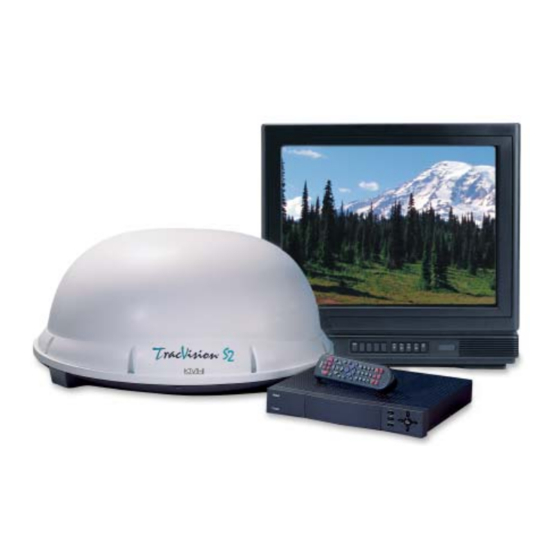
TracVision S2 System Overview A complete satellite TV system includes the TracVision S2 connected to an integrated receiver decoder (IRD) and a television set. A desktop or laptop computer is used to conduct diagnostics. -
Page 13: Tracvision S2 Components
User’s Manual provided with your selected IRD for complete operating instructions. Materials Provided with TracVision S2 Table 1-1 lists the units, cables, and materials packed in the TracVision S2 package by name and KVH part number. Component Antenna Unit RF Cable (28 ft) Data/Power Cable (28 ft) -
Page 14: Additional Materials Required For Tracvision S2 Use
1.3.1 Additional Materials Required for TracVision S2 Use To make full use of your new TracVision S2 and receive satellite TV, you will need to provide/purchase the following: • Television • Appropriate IRD for your selected satellite TV service 54-0196 Rev. A... -
Page 15: Installation
Installation TracVision S2 is designed for simple installation and setup. Just follow these easy steps: Step Choose the antenna location Mount the antenna unit Connect the system components Activate the IRD Check out the system Tools and Materials Required •... -
Page 16: Table 2-2 Kitpack Contents
A Guide to TracVision S2 Table 2-2 Kitpack Contents Kitpack Contents Table 2-2 lists the materials provided in the TracVision S2 kitpack. Part Switchplate Assembly Tie-wraps RJ11 Handset Cable Clam Shell Ventilator #6 x ⁄ " Thread-forming Screws ⁄ "-20 x ⁄... -
Page 17: Choosing The Best Location
Choosing the Best Location • Since the TracVision antenna requires a clear view of the southern sky to receive satellite signals, the ideal antenna site has an unobstructed view of the horizon/satellite all around. • Keep the antenna clear of any obstructions on the roof (e.g., air conditioners). -
Page 18: Mounting The Antenna Unit
A Guide to TracVision S2 Always lift the antenna unit by the gray baseplate, never by the radome! Figure 2-3 Proper Orientation of the Antenna Unit Mounting Plate Arrows The mounting plate arrows may face either forward or backward along the centerline of the vehicle for more convenient installation. -
Page 19: Factory-Drilled Drain Hole Locations
8. Reposition the antenna, lining up the mounting plate holes with the holes in the roof. Attach the mounting plates to the roof using rivets (or appropriate fasteners). Seal all rivet heads and edges with silicone. 9. Remove and save the 8 pan head screws and flat washers that secure the radome to the baseplate. - Page 20 A Guide to TracVision S2 Figure 2-6 Forward Shipping Restraint (Arranged for Shipping) Figure 2-7 TracVision S2 Shipping Restraints (Top View, Installed for Shipping) Do not discard the shipping restraints. They should be stowed for future use in case the antenna unit needs to be removed and shipped to another location.
-
Page 21: Tracvision S2 Shipping Restraints (Storage Position)
8 pan head screws and flat washers removed Step 15. Drill the cable access hole (marked in vehicle’s roof. 54-0196 Rev. A Figure 2-9 Rotating Plate Shipping Restraint Storage Figure 2-10 TracVision S2 Shipping Restraints (Storage Position) Forward Shipping Restraint Step 4) in the Installation... -
Page 22: Connecting System Components
A Guide to TracVision S2 Figure 2-11 Switchplate Cutout Dimensions Figure 2-12 Antenna Baseplate Connectors Connecting System Components The following sections provide instructions for properly wiring the antenna unit to the components inside the vehicle. Locating the Switchplate Before running cables, you need to determine the location for the TracVision S2 switchplate. -
Page 23: Connecting The Antenna To The Switchplate
When shipped from the factory, the antenna’s RF connectors are protected with caps. Leave the cap installed on the RF2 connector unless you are going to connect a second RF cable to the TracVision S2. -
Page 24: Figure 2-14 Installing Three Or Four Irds Using An Active Multiswitch
IRDs to function properly. 2-10 Installing Two IRDs and TVs To connect a second TV and IRD to the TracVision S2 system, you must connect a second RF cable to the antenna’s RF2 connector (see Figure 2-12). -
Page 25: Sealing The Cable Access Hole
4. Terminate all unused output connectors with 75 ohm DC blocks (Channel Master #7184, Radio Shack #15-1259 or equivalent). 2.3.3 Sealing the Cable Access Hole Once the RF and data/power cables are connected to the antenna, you need to seal and cover the cable access hole to protect against leakage. -
Page 26: Connecting The Switchplate To Vehicle Power
A Guide to TracVision S2 Before connecting the antenna unit to vehicle power, remove the appropriate vehicle fuse to prevent a short circuit. Replace the fuse after the connection to vehicle power is complete. 2-12 2.3.5 Connecting the Switchplate to Vehicle Power The switchplate must be connected to a +12 Vdc, 2.5-3.5 amp... -
Page 27: Activating The Ird
Data Connection Turn on the IRD and press the switchplate’s POWER button to power up the TracVision S2 system. Observe messages on your TV screen to verify proper operation. Some messages originate in the IRD, others are generated in the TracVision S2 circuits. - Page 28 A Guide to TracVision S2 Table 2-3 TracVision S2 Operational Messages The DISH Network and some newer IRDs (e.g., the Sony A50) give priority to internal IRD messages rather than on-screen messages. KVH recommends that the maintenance port be used to...
-
Page 29: Checking Out The System Without An Ird Data Connection
2.5.2 Checking Out the System Without an IRD Data Connection To ensure that the system is configured and operating properly, you will need to check the data provided in the system’s startup routine. To do so, you need to connect a PC to the antenna baseplate’s maintenance port. -
Page 30: Configuring Tracvision S2 For Remote Satellite Dish Operation
Configuration 2-16 4. Press the switchplate’s POWER button to apply power to the TracVision S2 system and wait for the system to fully initialize. Data should be scrolling on the PC display to identify any system problems detected. If no data is seen, recheck your connections and the terminal software setup. -
Page 31: Using Your Tracvision S2
Simply go to our web site at: footprint/index.html. Turning On the System The TracVision S2 system is easy to use. To turn on the TracVision S2 system, follow the steps below. 1. Park your vehicle. 2. Turn on the IRD and the television. -
Page 32: Switchplate Front Panel
If connected to an IRD Low- speed Data Port: As part of the startup process, the TracVision S2 system will default to Channel 200, a program directory. This is the system’s means of verifying that it has identified and is tracking the correct satellite. -
Page 33: Tracking The Correct Satellite
Satellite Selection.” 3.2.1 Using the IRD for Satellite Selection If your TracVision S2 is connected to an IRD’s low-speed data port, the antenna will automatically find and track the correct satellite based on the information it receives from the IRD. No user interaction is required. -
Page 34: Turning Off The System
POWER button (see Watching Television Turn on the TracVision S2 after your vehicle is parked. Once the startup procedure is complete and the antenna is locked onto the correct satellite, the TracVision S2 does not need to be turned on. -
Page 35: Troubleshooting
Causes and Remedies for Common Operational Issues There are a number of common issues that can affect the signal reception quality or the operation of the TracVision S2. The following sections address these issues and potential solutions. 54-0196 Rev. A... -
Page 36: Blown Fuse Or Improper Wiring
Refer to Section 2.1, “Choosing the Best Location,” certain that the TracVision S2 unit is in the optimal location. Simply moving the vehicle to clear an external obstruction will also restore signal quality. -
Page 37: Satellite Coverage Issue
RF cabling. 4.1.6 Type of Multiswitch Used An active (not passive) multiswitch must always be used to connect the TracVision S2 system to multiple IRDs. Refer to Section 2.3.2, “Connecting the Antenna to the IRD” proper multiswitch/multiple IRD cabling. -
Page 38: Ac Power Fluctuating
A Guide to TracVision S2 The long-term fix, typically done at original system installation, is to install an Uninterruptible Power Supply (like those available for use with computer systems) on the IRD. Be sure to specify a UPS with adequate available current for all devices attached to it. -
Page 39: Failed Ird Status Check
If the system tests achieves a result of NONE , there is no communication at all between the antenna unit and the IRD. Solution Check to be certain the IRD and TracVision S2 are connected properly at the low-speed data port and that both are powered on. Refer to Section 2.3, “Connecting System Components”... -
Page 40: Antenna Lnb Faults
TracVision S2 LNB. Computer Diagnostics TracVision S2 has been designed to provide diagnostic readouts viewed on the TV screen (DIRECTV only) or on a personal computer having an RS-232 serial communication port. If you are... -
Page 41: Maintenance Port Parser Commands
• 1 start bit • 1 stop bit • no flow control 4. Apply power to the TracVision S2 system and allow the system to complete full initialization. Data should be scrolling on the PC display to identify any system problems detected. If no data is seen, recheck your connections and the terminal software setup. -
Page 42: Maintenance
If you have any questions, please call your local authorized dealer or installer, or contact KVH directly. Preventive Maintenance TracVision S2 requires minimal preventive maintenance. The following tasks are sufficient to maintain peak performance. Monthly •... -
Page 43: Replaceable Parts
Radome Assembly Baseplate Assembly Data/Power Cable RF Cable CPU PCB System Fuse It is recommended that all other technical difficulties be resolved by returning the TracVision S2 unit to an authorized service provider. Part Number 02-0953-10 02-1244-02 32-0730-28 32-0417-28 02-1144-01... -
Page 44: Field Replaceable Unit Procedures
Field Replaceable Unit Procedures The following subsections provide detailed procedures for repairing or swapping out field replaceable units. The procedures refer to labeled items presented on the following diagrams. PCB Cover 3.15-amp Fuse Linear Actuator 54-0196 Rev. A Always lift the antenna unit by the gray baseplate, never by the radome or any portion of the antenna assembly! -
Page 45: Pcb Removal And Replacement
A Guide to TracVision S2 Figure 5-3 Antenna Assembly When carrying out maintenance on the PCB, be sure to not drop any of the small screws inside the mechanism. If a screw is lost within the baseplate, it must be retrieved to avoid causing any damage when the unit rotates. -
Page 46: Figure 5-4 Removing The Pcb Cover
54-0196 Rev. A Figure 5-4 Removing the PCB Cover PCB Cover TracVision S2 is equipped with a 5x20 mm, 3.15-amp, 250 volt fast- blow fuse, which is mounted on the PCB. To access and replace the fuse, remove the PCB cover. -
Page 47: Antenna Lnb Replacement
A Guide to TracVision S2 When replacing the LNB, make certain to restore it to its original orientation, as shown in Figure 5-3. The CALLNB Function requires the antenna to be pointed directly at the satellite peak before performing this routine. Using the FINDSAT... - Page 48 7. The system must respond with the following message: CALLNB: PASS CALLNB: FAIL , return to Step 3 and retry the procedure, making sure to achieve the highest possible RF signal peak. 8. Record the Cold Sky Average and the RFGAIN value reported in Step 7.
-
Page 49: Preparation For Shipment
A Guide to TracVision S2 When rotating the azimuth mechanism by hand, go slowly! Hitting the mechanical stops with excessive force will damage the azimuth limit switch. Figure 5-6 Attaching the Shipping Restraints to the Antenna Baseplate Figure 5-7 Securing the Forward... -
Page 50: Table A-1 Tracvision S2 System Specifications
32" wide x 14.8" high, 33 lbs Dual Output 9600 bps, 8,N,1,EIA, RS232 º º to 75 º º º º F to 131 º º F to 185 to 100 percent System Specifications Table A-1 TracVision S2 System Specifications... -
Page 51: Comprehensive Tracvision S2 System Wiring Diagram
Comprehensive TracVision S2 System Wiring Diagram Appendix B Comprehensive TracVision S2 System Wiring Diagram The wiring diagram is presented on the following page. 54-0196 Rev. A... -
Page 53: Appendix C Switchplate Template
Switchplate Template Appendix C Switchplate Template 1.85" 2.35" 54-0196 Rev. A... -
Page 54: Appendix D Echostar Ird Activation Procedure
- The screen will show you the Azimuth and Elevation to the satellite. Write this down. 7. Connect a PC to the antenna switchplate’s maintenance port. 8. Turn on the TracVision S2. HALT<CR> 9. Type after receiving the message *** Entering Search Mode 1 ***. - Page 55 A Guide to TracVision S2 The Signal Strength Meter is located on the bottom of the “Point Dish and Signal Strength” Screen. This Signal Strength Meter is Red in color, and turns Green when the proper satellite is located. Turning the IRD off with the remote puts the IRD in standby mode.
-
Page 56: Appendix E Startup Data Sequences
NOT connected to an IRD low-speed data port. Both sections show two routines. One is the standard, full initialization routine; the second is that registered by TracVision S2 if it is turned on and acquires the satellite via the “Instant On” operation (described in TracVision S2”). - Page 57 Saved Sat Pos: AZ = 327.70, EL = “Instant On” Startup Sequence ?PGM KVH TracVision S2 Rev X - Version X.XX - Serial Number XXXXXXXX Instant On --------------------------------System skips limit switch test Limit Switch Status: PASS-----------------PASS is expected *** Initializing IRD ***...
-
Page 58: System Not Connected To Ird Data
System Not Connected to IRD Data Standard Startup Sequence ?PGM KVH TracVision S2 Rev X - Version X.XX - Serial Number XXXXXXXX Limit Switch Test Limit Switch Status: PASS-----------------PASS is expected *** Initializing IRD *** Send APG OSD On Try MPG IRD Type... - Page 59 +POS: 348.8 23.3 2010 “Instant On” Startup Sequence ?PGM KVH TracVision S2 Rev X - Version X.XX - Serial Number XXXXXXXX Instant On --------------------------------System skips limit switch test Limit Switch Status: PASS-----------------PASS is expected *** Initializing IRD *** Send APG OSD On...
- Page 60 +POS: 360.0 22.5 1976 Switch held: wrong satellite--------------SAT SELECT switch pressed Exclude: No longer search AZ = KVH TracVision S2 Rev X - Version X.XX - Serial Number XXXXXXXX Limit Switch Test Limit Switch Status: PASS *** Initializing IRD ***...
-
Page 61: Table F-1 System Commands
Appendix F Maintenance Port Parser Commands TracVision S2 system parser commands are parsed when the system receives an ASCII carriage return (Hex 0D). An ASCII line feed (Hex 0A) is permitted but is ignored in any transmitted command. All system responses are terminated with an ASCII carriage return followed by a line feed and ending with either an acknowledge character (ASCII >... -
Page 62: Manual Positioning Commands
A Guide to TracVision S2 Table F-2 Manual Positioning Commands Manual Positioning Commands To execute the following commands, first put the antenna unit in idle mode by typing HALT and pressing “ENTER.” Positioning commands may be entered after the antenna comes to rest. -
Page 63: Operational Commands
Azimuth CCW Step Function: commands a 0.1 deg CCW manual step in azimuth angle Command: Argument: none Response: echoes the command Elevation UP Step Function: commands a 0.1 deg UP manual step in elevation angle Command: Argument: none Response: echoes the command Elevation DOWN Step Function: commands a 0.1 deg DOWN manual step in elevation... -
Page 64: Target And Signal Commands
A Guide to TracVision S2 Table F-4 Target and Signal Commands Target and Signal Commands Report Target Location Function: reports the target (satellite) location in the baseplate frame and uses the saved satellite position Command: TGTLOCATION Argument: none Response: Target Location = E XXX, A XXXX... - Page 65 Limited Warranty on Hardware KVH Industries, Inc. warrants the KVH product purchased against defects in materials for a period of TWO (2) years and against factory labor costs for a period of ONE (1) year from the date of original retail purchase by the original purchaser.
- Page 66 ® KVH Industries, Inc. 50 Enterprise Center • Middletown, RI 02842 • U.S.A. Phone: +1 401 847-3327 • Fax: +1 401 849-0045 • E-mail: info@kvh.com • Internet: www.kvh.com ® and TracVision ® are registered trademarks of KVH Industries, Inc.