Table of Contents
Advertisement
Advertisement
Table of Contents

Related Manuals for PEUGEOT Vivacity


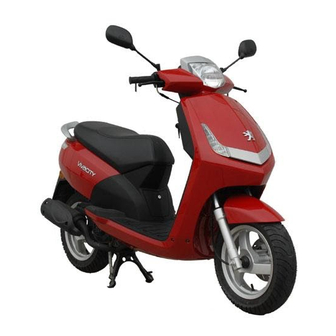
Summary of Contents for PEUGEOT Vivacity
- Page 1 Sales division Technical network leadership WORKSHOP MANUAL Workshop manual Technical network leadership Reproduction or translation, even partial, is forbidden without the written consent of Peugeot Motocycles...
-
Page 3: Table Of Contents
Starting up after overhauling the engine ....................9 TIGHTENING TORQUES ..........................10 Engine part ..............................10 Body panels .............................10 Cycle part..............................11 Standard ..............................11 SPECIAL TOOLS ............................12 LOCATION OF COMPONENTS........................14 Reproduction or translation, even partial, is forbidden without the written consent of Peugeot Motocycles... - Page 4 Removal of the float, needle valve and jets....................... 41 Removal of the engine speed adjuster screw and mixture control screw............42 Reassembly .............................43 Removal of the power unit ........................45 Reproduction or translation, even partial, is forbidden without the written consent of Peugeot Motocycles...
-
Page 5: Products Danger Symbols Used
Used batteries. collection point. People's safety can be seriously affected if Compulsory Operation that can be the recommendations are not fully gloves dangerous for people. respected. Reproduction or translation, even partial, is forbidden without the written consent of Peugeot Motocycles... - Page 6 Indicate the specific procedures that shall New part Use a new part. be followed in order not to damage the vehicle. Reproduction or translation, even partial, is forbidden without the written consent of Peugeot Motocycles...
-
Page 7: Characteristics
1.3 l Chassis Chassis Steel tube Hydraulic telescopic fork. Ø32 mm Front suspension Travel: 75 mm Combined spring and hydraulically-damped shock absorber Rear suspension Travel: 65 mm Reproduction or translation, even partial, is forbidden without the written consent of Peugeot Motocycles... -
Page 8: Dimensions And Weight
Brake drum diameter 110 mm Brake lining thickness 4 mm Chassis markings Engine marking (1) number and manufacturer's plate Engine number. (2) Reproduction or translation, even partial, is forbidden without the written consent of Peugeot Motocycles... -
Page 9: Service Schedule And Commissioning
9400 9600 Time required for maintenance V: Check, clean, adjust. C: Inspect and change if necessary. R: Change. * Depending on equipment. G: Check, clean, lubricate. Reproduction or translation, even partial, is forbidden without the written consent of Peugeot Motocycles... -
Page 10: Battery Preparation (Except Battery Without Maintenance)
Check the tyre pressures cold. Check operation of the lights, flashers, horn, and brake light. Check the different warning lights work. Carry out a road test. Reproduction or translation, even partial, is forbidden without the written consent of Peugeot Motocycles... -
Page 11: Special Important Points
The light comes on when the ignition is turned on to check it is operational and comes off as soon as the engine starts if there is no incident. When starting the engine hot or cold do not accelerate. Reproduction or translation, even partial, is forbidden without the written consent of Peugeot Motocycles... -
Page 12: Tightening Torques
6 to 8 Nm Saddle storage compartment 8 to 10 Nm Rear panels 6 to 8 Nm Grab handle 20 to 25 Nm Rear mudguard 2 to 4 Nm Reproduction or translation, even partial, is forbidden without the written consent of Peugeot Motocycles... -
Page 13: Cycle Part
10 Nm Nut and bolt 8 mm diameter 22 Nm Nut and bolt 10 mm diameter 35 Nm Nut and bolt 12 mm diameter 55 Nm Reproduction or translation, even partial, is forbidden without the written consent of Peugeot Motocycles... -
Page 14: Special Tools
Steeing head 69104 Pin nut 750069 753726 cup push tool Modified Pin Ø10 casing 750069 69104 754006 67706 pitch 125 opening plate Reproduction or translation, even partial, is forbidden without the written consent of Peugeot Motocycles... - Page 15 Casing 755983 68007 757860 Steering tool opening tool Flywheel Steeing head 755985 68007 757990 puller cup push tool 755996 Hose clamp (*) New or modified tool. Reproduction or translation, even partial, is forbidden without the written consent of Peugeot Motocycles...
-
Page 16: Parts List
10. Fuel gauge 4. Oil level indicator 11. Horn 5. Oil pump 12. Outside temperature sensor 6. HT coil 13. Speed sensor 7. Low oil level warning light Reproduction or translation, even partial, is forbidden without the written consent of Peugeot Motocycles... -
Page 17: Body Panels
10. Central panel 4. Front storage compartment 11. Footboard 5. Rear shield 12. Grab handle 6. Front mudguard 13. Rear panels 7. Front wheel 14. Bottom panel Reproduction or translation, even partial, is forbidden without the written consent of Peugeot Motocycles... -
Page 18: Body Component Sequence Of Disassembly
5. Rear shield 12. Grab handle 6. Front mudguard 13. Rear panels 7. Front wheel 14. Bottom panel *This item may be removed on its own. Reproduction or translation, even partial, is forbidden without the written consent of Peugeot Motocycles... -
Page 19: Removal Of The Rear Storage Compartment
- Remove the rear storage compartment. See: Procedure 1. page 17. - Remove the grab handle. (3 screw). (1) - Remove the central cover panel.(5 screw). Reproduction or translation, even partial, is forbidden without the written consent of Peugeot Motocycles... - Page 20 BODY PANELS - Remove the rear cover assembly. (5 screw) Disconnect the taillights. - Remove the splash guard. (6 screw) - Separate the 3 fairings. (4) Reproduction or translation, even partial, is forbidden without the written consent of Peugeot Motocycles...
-
Page 21: Removal Of The Front Storage Compartment
(11 screw) - Disconnect the horn. Removal of the rear shield panel Procedure 4. - Remove the 4 upper screws that secure the rear shield panel. Reproduction or translation, even partial, is forbidden without the written consent of Peugeot Motocycles... -
Page 22: Removal Of The Front Shield Panel
When re-installing, use a new nut. - Remove the front wheel. - Remove the front mudguard.(1). (4 screw) - Remove the 5 screws that secure the front shield panel. Reproduction or translation, even partial, is forbidden without the written consent of Peugeot Motocycles... -
Page 23: Removal Of The Footboard
- Remove the central cover panel. (5 screw). - Remove the rear shield panel. See: Procedure 4. page 19. - Remove the bottom panel. (14 screw) - Remove the footboard. (4 screw) Reproduction or translation, even partial, is forbidden without the written consent of Peugeot Motocycles... -
Page 24: Removal Of The Instrument Cluster
(6 screw) - Disconnect the instrument cluster. - Remove the handlebar rear cover and instrument cluster assembly. (4 screw) - Remove the instrument cluster. (4 screw) Reproduction or translation, even partial, is forbidden without the written consent of Peugeot Motocycles... -
Page 25: Service Operations
- Fit the air filter. - Fit the gasket. (2) - Install the air filter cover. Reproduction or translation, even partial, is forbidden without the written consent of Peugeot Motocycles... -
Page 26: Front Brake Pads
When re-installing, use a new pin retainer. After refitting, actuate the brake levers several times to bring the brake pads against the brake disc. Reproduction or translation, even partial, is forbidden without the written consent of Peugeot Motocycles... -
Page 27: Checking The Brake Fluid Level
- Remove the handlebar front cover. (6 screw) - Remove the cover and the diaphragm from the master cylinder. (2 screw) - Add brake fluid until it reaches the maximum level. Reproduction or translation, even partial, is forbidden without the written consent of Peugeot Motocycles... -
Page 28: Rear Brake Linings
Disassembly. - Disconnect the air hose from the exhaust. - Remove the exhaust holder plate. (2)(2 screw) - Remove the exhaust. (2 screws and 2 nuts) Reproduction or translation, even partial, is forbidden without the written consent of Peugeot Motocycles... - Page 29 - Remove the adjusting nut, the barrel (5) and the brake control cable. (6) - Remove the brake arm (7), the brake cam (8) and the spring. Reproduction or translation, even partial, is forbidden without the written consent of Peugeot Motocycles...
- Page 30 - Install the exhaust. Use a new exhaust gasket. • Exhaust to cylinder mounting nut: Tightening torque: 15 Nm. • Exhaust to casing mounting bolt: Tightening torque: 20 Nm. Reproduction or translation, even partial, is forbidden without the written consent of Peugeot Motocycles...
-
Page 31: Transmission
- Remove the fixed flange nut and washer. - Remove the fixed flange. 752237 - Remove the belt. - Remove the drive pulley (1) together with the guide hud. Reproduction or translation, even partial, is forbidden without the written consent of Peugeot Motocycles... - Page 32 - The guides shall be replaced if they show signs of wear. - When refitting, respect the way the rollers are installed. - Grease the moving flange bore lightly (high temperature grease). Reproduction or translation, even partial, is forbidden without the written consent of Peugeot Motocycles...
-
Page 33: Checking The Drive Belt
Mini. thickness 1 mm. - Make sure surface of the plates in contact with the belt does not show any cracks or signs of abnormal wear. Reproduction or translation, even partial, is forbidden without the written consent of Peugeot Motocycles... -
Page 34: Replacing The Clutch Lining Assembly
- Remove nut (1) using spanner P/N 756725. - Slacken tool P/N 752127. - Remove the clutch lining assembly. (2) - When re-installing the driven pulley, lubricate the needle bearing. (3) Reproduction or translation, even partial, is forbidden without the written consent of Peugeot Motocycles... -
Page 35: Removal Of The Fuel Filter
- Remove the fuel filter. (3) When re-installing, respect the direction of installation of the filter shown by the arrow which indicates in which direction the fuel flows. Reproduction or translation, even partial, is forbidden without the written consent of Peugeot Motocycles... -
Page 36: Miscellaneous Operations
• The nut. • the rubber washer. • The nut. • The dust cover. • The upper cone. - Remove the fork. - Remove the caged ball bearings. Reproduction or translation, even partial, is forbidden without the written consent of Peugeot Motocycles... - Page 37 - Using a chisel, pry the steering head cup off by pressing the tool behind the dust cover. Reassembly. - Install the following new parts: • The dust cover.(1) • The fork cone.(2) Reproduction or translation, even partial, is forbidden without the written consent of Peugeot Motocycles...
-
Page 38: Steering System Tightening Method
- Install the upper cone.(4) - Install the dust cover.(5) - Fit and tighten the nut.(6) Tightening torque: 40 Nm. - Loosen and re-tighten the nut. Tightening torque: 23 Nm. Reproduction or translation, even partial, is forbidden without the written consent of Peugeot Motocycles... - Page 39 - Fit the lock washer (6) in the notches of the 2 nuts. - Install the steering head locknut and tighten it. (7) Tightening torque: 70 Nm. Reproduction or translation, even partial, is forbidden without the written consent of Peugeot Motocycles...
-
Page 40: Removal Of The Fuel Pump
When re-installing, use a new gasket. Removal of the fuel tank - Remove the footboard. See: Procedure 5 page 21. - Remove the footboard supports. (1)(4 screw) Reproduction or translation, even partial, is forbidden without the written consent of Peugeot Motocycles... - Page 41 - Put a hose clamp P/N 755996 on the fuel inlet hose (1). - Disconnect the fuel supply hose. - Disconnect the fuel gauge. - Remove the fuel tank. 755996 Reproduction or translation, even partial, is forbidden without the written consent of Peugeot Motocycles...
-
Page 42: Removal Of The Carburettor
- Dismantle the valve equipped with its needle, spring and carburettor chamber cap. - Dismantle the needle (7) by pushing it out in order to remove the clips (8). Reproduction or translation, even partial, is forbidden without the written consent of Peugeot Motocycles... -
Page 43: Removal Of The Float, Needle Valve And Jets
- Remove the chamber. (4 screw) - Remove the paper gasket. (11) - Loosen the float pin clamping screw (12). Remove the float (13) with its pin and needle valve. Reproduction or translation, even partial, is forbidden without the written consent of Peugeot Motocycles... -
Page 44: Removal Of The Engine Speed Adjuster Screw And Mixture Control Screw
Do not turn the screws home forcefully. - Remove the idle screw and the mixture control screw with their spring. Reproduction or translation, even partial, is forbidden without the written consent of Peugeot Motocycles... -
Page 45: Reassembly
- Fit and tighten the screw (C) that secures the float pin. Install a new paper gasket. (11) Fit teh float chamber. - Fit and tighten the 4 screws of teh float chamber. Reproduction or translation, even partial, is forbidden without the written consent of Peugeot Motocycles... - Page 46 11. Float chamber gasket. 12. Float pin screw. 13. Float and needle. 14. Idle jet. 15. Main jet. 16. Venturi. 17. Idle screw. 18. Mixture screw. Reproduction or translation, even partial, is forbidden without the written consent of Peugeot Motocycles...
-
Page 47: Removal Of The Power Unit
• The fuel supply hose (6). • The oil supply hose (7). • The vacuum pressure hose. (8) • The pulsair reed valve hose. (9) • The rear brake control cable. Reproduction or translation, even partial, is forbidden without the written consent of Peugeot Motocycles... - Page 48 Tightening torque: 45 Nm. - Remove the linkrod-to-frame pin nut. (11) - Tightening torque: 60 Nm. When re-installing, use a new nut. - Remove the linkrod-to-frame connecting pin. (12) Reproduction or translation, even partial, is forbidden without the written consent of Peugeot Motocycles...
- Page 49 MISCELLANEOUS OPERATIONS - Lift the rear of the machine. - Remove the power propulsion unit from the frame. Reproduction or translation, even partial, is forbidden without the written consent of Peugeot Motocycles...
- Page 52 P/N. MA0003GB In our permanent concern to make improvements PEUGEOT MOTOCYCLES reserves the right to suppress, modify, or add any reference mentioned. DC/PS/APV Printed in the E.U. 06/2008 (non contractual pictures)