
Related Manuals for Aaeon EMB-9658T Mini-ITX


Summary of Contents for Aaeon EMB-9658T Mini-ITX
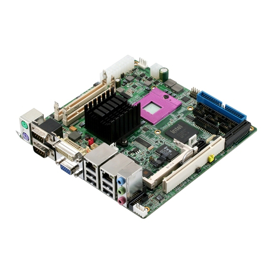
- Page 1 Mini -ITX E M B - 9 6 5 8 T EMB-9658T ® Intel Core 2 Duo/ ® Celeron M Processor, Mini-ITX ® Intel 82573L, 82566MM Ethernet TPM 1.2 VIA VT1708B Audio & Mini PCI EMB-9658T Manual Rev.A 1 July, 2009...
-
Page 2: Copyright Notice
AAEON assumes no liabilities resulting from errors or omissions in this document, or from the use of the information contained herein. AAEON reserves the right to make changes in the product design without notice to its users. - Page 3 M i n i - I T X E M B - 9 6 5 8 T Acknowledgments All other products’ name or trademarks are properties of their respective owners. Award is a trademark of Award Software International, Inc. CompactFlash is a trademark of the Compact Flash ™...
-
Page 4: Packing List
M i n i - I T X E M B - 9 6 5 8 T Packing List Before you begin installing your card, please make sure that the following materials have been shipped: 1709070500 SATA Cable 1702151200 Onboard SATA Power Cable M206908T00 Metal I/O Bracket Quick Installation Guide... -
Page 5: Table Of Contents
M i n i - I T X E M B - 9 6 5 8 T Contents Chapter 1 General Information 1.1 Introduction..............1-2 1.2 Features ..............1-3 1.3 Specifications ............1-4 Chapter 2 Quick Installation Guide 2.1 Safety Precautions ..........2-2 2.2 Location of Connectors and Jumpers ...... - Page 6 M i n i - I T X E M B - 9 6 5 8 T 2.18 USB Connector/10/100/1000 Base-Tx Ethernet Connector(1) (CN5)............2-15 2.19 USB Connector/10/100/1000 Base-Tx Ethernet Connector(2) (CN6)............2-15 2.20 TV_Out Connector (CN7)........2-16 2.21 LCD Inverter Connector (CN8) ......
- Page 7 M i n i - I T X E M B - 9 6 5 8 T 2.41 CPU Fan Connector (CN29) ....... 2-24 2.42 Front Panel Connector (CN30) ......2-25 2.43 CompactFlash Connector (CN31)......2-25 2.44 ATX Power_12V Connector(CN32) ...... 2-26 2.45 SATA Power Connector (CN33) ......
-
Page 8: Chapter 1 General Information
M i n i - I T X E M B - 9 6 5 8 T Chapter General Information 1- 1 Chapter 1 General Information... -
Page 9: Introduction
M i n i - I T X E M B - 9 6 5 8 T 1.1 Introduction ® The EMB-9658T adopts the latest Intel Core™ 2 Duo/ ® ® Celeron (Socket-P based) processors Intel GME965+ICH8M chipset better power-management capabilities and enhanced performance. -
Page 10: Features
M i n i - I T X E M B - 9 6 5 8 T 1.2 Features Intel® Core™ 2 Duo/ Celeron® M (Socket-P Based) Processors Intel® GME965 + ICH8M (-E Optional for RAID) DDRII 533/667 Memory, Max. 4GB Gigabit Ethernet x 2, with one 82566MM support iAMT 2.5 18/24 bit Dual-Channel LVDS, DVI/TV/CRT, SDVO Connector for 2nd 18/24 bit Dual-Channel LVDS/DVI... -
Page 11: Specifications
M i n i - I T X E M B - 9 6 5 8 T 1.3 Specifications System Form Factor Mini-ITX Processor Intel® Core™ 2 Duo/ Celeron® M (Socket-P based) Processors System Memory 200-pin DDRII SODIMM x 2, Max. - Page 12 M i n i - I T X E M B - 9 6 5 8 T Battery Lithium battery Power Requirement DC 12V / AT/ ATX Board Size 6.7" (L) x 6.7" (W) (170mm x 170mm) Gross Weight 1.1lb (0.5kg) Operating Temp.
- Page 13 M i n i - I T X E M B - 9 6 5 8 T 1080i/1080p DVI-I x 1 Storage EIDE x 1 (shared signals with CompactFlash™) SATAII x 2 Serial Port RS-232 x 4, RS-232/422/485 x 1, TTL x 1 Parallel Port SPP/ EPP/ ECP mode USB2.0 x 8...
-
Page 14: Chapter 2 Quick Installation Guide
M i n i - I T X E M B - 9 6 5 8 T Chapter Quick Installation Guide Notice: The Quick Installation Guide is derived from Chapter 2 of user manual. For other chapters further installation instructions, please refer to the user manual CD-ROM that came with the product. -
Page 15: Safety Precautions
M i n i - I T X E M B - 9 6 5 8 T 2.1 Safety Precautions Always completely disconnect the power cord from your board whenever you are working on it. Do not make connections while the power is on, because a sudden rush of power can damage sensitive electronic components. -
Page 16: Location Of Connectors And Jumpers
M i n i - I T X E M B - 9 6 5 8 T 2.2 Location of Connectors and Jumpers Locating Connectors and Jumpers (Component Side) 2 - 3 Chapter 2 Quick Installation Guide... - Page 17 M i n i - I T X E M B - 9 6 5 8 T Locating Connectors and Jumpers (Solder Side) 2 - 4 Chapter 2 Quick Installation Guide...
-
Page 18: Mechanical Drawing
M i n i - I T X E M B - 9 6 5 8 T 2.3 Mechanical Drawing Component Side 2 - 5 Chapter 2 Quick Installation Guide... -
Page 19: Solder Side
M i n i - I T X E M B - 9 6 5 8 T Solder Side 2 - 6 Chapter 2 Quick Installation Guide... -
Page 20: List Of Jumpers
M i n i - I T X E M B - 9 6 5 8 T 2.4 List of Jumpers The board has a number of jumpers that allow you to configure your system to suit your application. The table below shows the function of each of the board's jumpers: Jumpers Label... -
Page 21: List Of Connectors
M i n i - I T X E M B - 9 6 5 8 T 2.5 List of Connectors The board has a number of connectors that allow you to configure your system to suit your application. The table below shows the function of each of the board's connectors: Connectors Label... - Page 22 M i n i - I T X E M B - 9 6 5 8 T CN19 LPT Port Connector CN20 AT Power Connector CN21 PCI Express Slot CN22 USB Connector CN23 USB Connector CN24 Digital I/O Connector CN25 COM4 RS-232 Serial Port Connector CN26 COM3 RS-232 Serial Port Connector...
-
Page 23: Setting Jumpers
M i n i - I T X E M B - 9 6 5 8 T 2.6 Setting Jumpers You configure your card to match the needs of your application by setting jumpers. A jumper is the simplest kind of electric switch. It consists of two metal pins and a small metal clip (often protected by a plastic cover) that slides over the pins to connect them. -
Page 24: Lcd Inverter Voltage Selection (Jp1)
M i n i - I T X E M B - 9 6 5 8 T 2.7 LCD INVERTER Voltage Selection (JP1) Function +5V (Default) +12V 2.8 COM2 Ring/+5V/+12V Selection (JP2) Function +12V Ring (Default) 2.9 LCD Voltage Selection (JP3) Function +3.3V (Default) 2.10 Auto Power Button (JP4) -
Page 25: Atx Power Simulate At Power (Jp6)
M i n i - I T X E M B - 9 6 5 8 T 2.12 ATX Power Simulate AT Power (JP6) Function ATX or AT standard (Default) ATX Power Simulate AT Power 2.13 Connector Pin Assignment 2.14 DVI+CRT Connector (CN1) Signal Signal DVI_TX2-... -
Page 26: Audio Speaker Output (Cn2)
M i n i - I T X E M B - 9 6 5 8 T GREEN BLUE HSYNC DDCCLK HSYNC GREEN VSYNC BLUE DDCDAT 2.15 Audio Speaker Output (CN2) Signal SPK-R+ SPK-R- SPK-L+ SPK-L- 2 - 13 Chapter 2 Quick Installation Guide... -
Page 27: Audio 5.1 Channel / Spdif Connector (Cn4)
M i n i - I T X E M B - 9 6 5 8 T 2.16 COM1 RS-232&COM2 RS-232/422/485 (CN3) Signal Signal DCD1 RXD1 TXD1 DTR1 DSR1 RTS1 CTS1 DCD2(422TXD-/485DATA-) RXD2(422RXD+) TXD2(422TXD+/485DATA+) DTR2(422RXD-) DSR2 RTS2 CTS2 RI2/+5V/+12V 2.17 Audio 5.1 Channel / SPDIF Connector (CN4) Signal Signal Front-OUT-R... -
Page 28: Connector(1) (Cn5)
M i n i - I T X E M B - 9 6 5 8 T LFE-OUT CNE-OUT SPDIF-OUT SPDIF-IN 2.18 USB Connector/10/100/1000 Base-Tx Ethernet Connector(1) (CN5) Signal Signal LAN2 TCT LAN2 MDI0+ LAN2_MDI0- LAN2_MDI1+ LAN2_MDI1- LAN2_MDI2+ LAN2_MDI2- LAN2_MDI3+ LAN2_MDI3- LAN2_RCT LAN2_Active-... -
Page 29: Tv_Out Connector (Cn7)
M i n i - I T X E M B - 9 6 5 8 T LAN1_S100LED LAN1_S1000LED USBD0- USBD0+ USBD1- USBD1+ 2.20 TV_Out Connector (CN7) Signal Signal CVBS N.C. N.C. 2.21 LCD Inverter Connector (CN8) Signal VCC of LCD inverter (+5V/+12V) Adjust backlight ENBKL 2.22 CD-IN Connector (CN9) -
Page 30: Internal Keyboard Connector (Cn10)
M i n i - I T X E M B - 9 6 5 8 T 2.23 Internal Keyboard Connector (CN10) Signal KB CLK KB_DATA N.C. 2.24 Internal Mouse Connector (CN11) Signal MS CLK MS_DATA 2.25 LVDS-LCD Connector (CN12) Signal Signal ENBKL... -
Page 31: Sdvo Connector (Cn13)
M i n i - I T X E M B - 9 6 5 8 T LVDS2_TX2- LVDS2_TX2+ PPVCC LVDS2_TXCLK- LVDS2_TXCLK+ 2.26 SDVO Connector (CN13) Signal Signal SDVO_SPC SDVO_RST# SDVO_SPD SMBCLK SMBDATA SDVO_RED# SDVO_FLDSTALL# SDOV_RED SDVO_FLDSTALL SDVO_BLUE# SDVO_INT# SDVO_BLUE SDVO_INT SDVO_GREEN# SDVO_CLK#... -
Page 32: System Fan Connector(Cn14)
M i n i - I T X E M B - 9 6 5 8 T 2.27 System Fan Connector(CN14) Signal VCC of FAN Speed Sense Speed Control 2.28 RTC Battery Connector(CN16) Signal Battery Power input 2.29 GPS Connector(CN17) Signal GPS_LED GPS_TXD... -
Page 33: Lpt Port Connector (Cn19)
M i n i - I T X E M B - 9 6 5 8 T -12V PS_ON POWER OK +5VSB +12V 2.31 LPT Port Connector (CN19) Signal Signal STROBE PTD0 ERROR PTD1 INIT PTD2 SLIN PTD3 PTD4 PTD5 PTD6 PTD7 BUSY... -
Page 34: At Power Connector(Cn20)
M i n i - I T X E M B - 9 6 5 8 T 2.32 AT POWER Connector(CN20) Signal +12V -12V 2.33 PCI Express Slot (CN21) Signal Signal +12V +12V +12V +12V +12V SMBCLK SMBDAT +3.3V +3.3V +3.3V +3.3VSB PCIE_RESET#... -
Page 35: Usb Connector(Cn22)
M i n i - I T X E M B - 9 6 5 8 T PCIE1_CLKP PCIE1_CLKN PCIE1_TXP PCIE1_TXN PCIE1_RXP PCIE1_RXN PCIE2_TXP PCIE2_TXN PCIE2_RXP PCIE2_RXN PCIE3_TXP PCIE3_TXN PCIE3_RXP PCIE3_RXN PCIE4_TXP PCIE4_TXN PCIE4_RXP PCIE4_RXN PCIE2_CLKN PCIE2_CLKP 2.34 USB Connector(CN22) Signal Signal USBD6-... -
Page 36: Usb Connector(Cn23)
M i n i - I T X E M B - 9 6 5 8 T 2.35 USB Connector(CN23) Signal Signal USBD4- USBD4+ USBD5+ USBD5- 2.36 Digital I/O Connector (CN24) Signal Signal Digital-IN/ OUT Digital-IN/OUT Digital-IN/ OUT Digital-IN/ OUT Digital-IN/ OUT Digital-IN/ OUT Digital-IN/ OUT... -
Page 37: Com6 Rs-232 Serial Port Connector (Cn27)
M i n i - I T X E M B - 9 6 5 8 T N.C. 2.39 COM6 RS-232 Serial Port Connector (CN27) Signal Signal N.C. 2.40 IrDA Connector (CN28) Signal N.C. IRRX IRTX N.C. 2.41 CPU Fan Connector(CN29) Signal VCC of FAN Speed Sense... -
Page 38: Front Panel Connector (Cn30)
M i n i - I T X E M B - 9 6 5 8 T 2.42 Front Panel Connector (CN30) Signal Signal Power On Button (-) Power On Button (+) IDE LED (-) IDE LED (+) External Buzzer (-) External Buzzer (+) Power LED (-) Power LED (+) -
Page 39: Atx Power_12V Connector(Cn32)
M i n i - I T X E M B - 9 6 5 8 T ACTIVE# PDIAG# 2.44 ATX Power_12V Connector(CN32) Signal +12V +12V 2.45 SATA Power Connector (CN33) Signal +12V 2 - 26 Chapter 2 Quick Installation Guide... - Page 40 M i n i - I T X E M B - 9 6 5 8 T AAEON Main Board/ Daughter Board/ Backplane 有毒有害物质或元素 部件名称 铅 汞 镉 六价铬 多溴联苯 多溴二苯醚 (Pb) (Hg) (Cd) (Cr(VI)) (PBB) (PBDE) 印刷电路板 × ○...
-
Page 41: Chapter 3 Award Bios Setup
M i n i - I T X E M B - 9 6 5 8 T Chapter Award BIOS Setup Chapter 3 Award BIOS Setup 3-1... -
Page 42: System Test And Initialization
M i n i - I T X E M B - 9 6 5 8 T 3.1 System Test and Initialization These routines test and initialize board hardware. If the routines encounter an error during the tests, you will either hear a few short beeps or see an error message on the screen. -
Page 43: Award Bios Setup
M i n i - I T X E M B - 9 6 5 8 T 3.2 Award BIOS Setup Awards BIOS ROM has a built-in Setup program that allows users to modify the basic system configuration. This type of information is stored in battery-backed CMOS RAM so that it retains the Setup information when the power is turned off. - Page 44 M i n i - I T X E M B - 9 6 5 8 T Advanced Chipset Features Use this menu to change the values in the chipset registers and optimize your system performance. Integrated Peripherals Use this menu to specify your settings for integrated peripherals.
-
Page 45: Load Optimized Defaults
M i n i - I T X E M B - 9 6 5 8 T Load Optimized Defaults Use this menu to load the BIOS default values that are factory settings for optimal performance system operations. While AWARD has designated the custom BIOS to maximize performance, the factory has the right to change these defaults to meet their needs. -
Page 46: Chapter 4 Driver Installation
M i n i - I T X E M B - 9 6 5 8 T Chapter Driver Installation Chapter 4 Driver Installation... - Page 47 M i n i - I T X E M B - 9 6 5 8 T The EMB-9658T comes with an AutoRun CD-ROM that contains all drivers and utilities that can help you to install the driver automatically. Insert the driver CD, the driver CD-title will auto start and show the installation guide.
- Page 48 M i n i - I T X E M B - 9 6 5 8 T 4.1 Installation: Insert the EMB-9658T CD-ROM into the CD-ROM drive. And install the drivers from Step 1 to Step 5 in order. Step 1 – Install chip Driver 1.
- Page 49 M i n i - I T X E M B - 9 6 5 8 T Step 4 – Install Audio Driver 1. Click on the Step 4- Audio Driver folder and then double click on the SETUP.exe 2. Follow the instructions that the window shows 3.
-
Page 50: Appendix A Programming The Watchdog Timer
M i n i - I T X E M B - 9 6 5 8 T Appendix Programming the Watchdog Timer Appendix A Programming the Watchdog Timer A-1... -
Page 51: Programming
EMB-9658T utilizes ITE 8712 chipset as its watchdog timer controller. Below are the procedures to complete its configuration and the AAEON intial watchdog timer program is also attached based on which you can develop customized program to fit your application. Configuring Sequence Description After the hardware reset or power-on reset, the ITE 8712 enters the normal mode with all logical devices disabled except KBC. - Page 52 M i n i - I T X E M B - 9 6 5 8 T There are three steps to complete the configuration setup: (1) Enter the MB PnP Mode; (2) Modify the data of configuration registers; (3) Exit the MB PnP Mode.
- Page 53 M i n i - I T X E M B - 9 6 5 8 T WatchDog Timer Configuration Registers Configure Control (Index=02h) This register is write only. Its values are not sticky; that is to say, a hardware reset will automatically clear the bits, and does not require the software to clear them.
- Page 54 M i n i - I T X E M B - 9 6 5 8 T WatchDog Timer Configuration Register (Index=72h, Default=00h) WatchDog Timer Time-out Value Register (Index=73h, Default=00h) Appendix A Programming the Watchdog Timer A-5...
-
Page 55: It8712 Watchdog Timer Initial Program
M i n i - I T X E M B - 9 6 5 8 T A.2 IT8712 Watchdog Timer Initial Program .MODEL SMALL .CODE Main: CALL Enter_Configuration_mode CALL Check_Chip mov cl, 7 call Set_Logic_Device ;time setting mov cl, 10 ; 10 Sec dec al Watch_Dog_Setting: ;Timer setting... - Page 56 M i n i - I T X E M B - 9 6 5 8 T ; game port enable mov cl, 9 call Set_Logic_Device Initial_OK: CALL Exit_Configuration_mode MOV AH,4Ch INT 21h Enter_Configuration_Mode PROC NEAR MOV SI,WORD PTR CS:[Offset Cfg_Port] MOV DX,02Eh MOV CX,04h Init_1:...
- Page 57 M i n i - I T X E M B - 9 6 5 8 T Exit_Configuration_Mode ENDP Check_Chip PROC NEAR MOV AL,20h CALL Read_Configuration_Data CMP AL,87h JNE Not_Initial MOV AL,21h CALL Read_Configuration_Data CMP AL,12h JNE Not_Initial Need_Initial: Not_Initial: Check_Chip ENDP Read_Configuration_Data PROC NEAR MOV DX,WORD PTR CS:[Cfg_Port+04h]...
- Page 58 M i n i - I T X E M B - 9 6 5 8 T MOV DX,WORD PTR CS:[Cfg_Port+06h] IN AL,DX Read_Configuration_Data ENDP Write_Configuration_Data PROC NEAR MOV DX,WORD PTR CS:[Cfg_Port+04h] OUT DX,AL XCHG AL,AH MOV DX,WORD PTR CS:[Cfg_Port+06h] OUT DX,AL Write_Configuration_Data ENDP Superio_Set_Reg proc near...
- Page 59 M i n i - I T X E M B - 9 6 5 8 T push ax push cx xchg al,cl mov cl,07h call Superio_Set_Reg pop cx pop ax Set_Logic_Device endp ;Select 02Eh->Index Port, 02Fh->Data Port Cfg_Port DB 087h,001h,055h,055h DW 02Eh,02Fh END Main Note: Interrupt level mapping...
-
Page 60: Appendix B I/O Information
M i n i - I T X E M B - 9 6 5 8 T Appendix I/O Information Appendix B I/O Information B-1... -
Page 61: I/O Address Map
M i n i - I T X E M B - 9 6 5 8 T B.1 I/O Address Map Appendix B I/O Information B-2... - Page 62 M i n i - I T X E M B - 9 6 5 8 T Appendix B I/O Information B-3...
-
Page 63: Memory Address Map
M i n i - I T X E M B - 9 6 5 8 T B.2 Memory Address Map Appendix B I/O Information B-4... -
Page 64: Irq Mapping Chart
M i n i - I T X E M B - 9 6 5 8 T B.3 IRQ Mapping Chart Appendix B I/O Information B-5... -
Page 65: Dma Channel Assignments
M i n i - I T X E M B - 9 6 5 8 T B.4 DMA Channel Assignments Appendix B I/O Information B-6... - Page 66 M i n i - I T X E M B - 9 6 5 8 T Appendix Mating Connecotor C - 1 Appendix C Mating Connector...
-
Page 67: Appendix C Mating Connector
M i n i - I T X E M B - 9 6 5 8 T C.1 List of Mating Connectors and Cables The table notes mating connectors and available cables. Connector Mating Connector Available Cable P/N Function Label Cable Vendor Model no... - Page 68 M i n i - I T X E M B - 9 6 5 8 T or compatible) LVDS E-CALL 1.25mm Pitch CN12 Pins(E-call.011 0-01-553-300 or compatible) SDVO Catch 1.0mm Pitch 40 CN13 pins(Catch.120 4-710-40SM or compatible) Catch 2.54mm Pitch 3 CN14 pins (Catch 1190-700-042...
- Page 69 M i n i - I T X E M B - 9 6 5 8 T 0-10MSP or compatible) USB Port Catch 2.00mm Pitch 1709100201 CN23 10 pins Cable (Catch.1147-00 0-10MSP or compatible) Digital I/O Catch 2.00mm Pitch CN24 pins(Catch.114 7-000-10MSP or compatible)
- Page 70 M i n i - I T X E M B - 9 6 5 8 T or compatible) Front JIH VEI 2.54mm Pitch CN30 Panel 10 pins (JIH VEI.21N22564- 10S10B-01G-6/ or compatible) Catch 3.5mm Pitch CN32 Power 4Pins (Catch Socket 1121-700-04S or compatible)