Table of Contents

Related Manuals for RTS Cronus


Summary of Contents for RTS Cronus
- Page 1 Cronus Digital Intercom Matrix 9350-7770-000 Rev S 9/2008...
- Page 2 Telephone: 800-392-3497 9010-44400-001 Cronus Final Assembly, Fiber Linking Fax: 800-323-0498 Factory Service: 800-553-5992 9010-7770-000 Cronus Final Assembly, Coax Linking 9020-7800-000 Cronus AI/O Rear Card, MDR SCSI ETURN HIPPING NSTRUCTIONS 9020-7787-001 Cronus AI/O Rear Card, RJ12 Customer Service Department 690505 Cable Assy., CAT5, 7ft., black, RJ45 Telex Communications, Inc.
-
Page 3: Table Of Contents
Table Contents INTRODUCTION ..........3 ETHERNET SETUP FOR CRONUS .....27 General Description ..........3 Connecting Cronus to the PC and the Network ...27 Features ..............3 ......29 OWNLOAD IRMWARE FOR RONUS MAC A ....30 Differences between Cronus and ADAM ....4... - Page 4 Serial Command Table ........73 Codec Specifications ..........75 RVON-C Default Setup ........76 RVON-C QUICK START ........ 77 Install Front and Back Cards in Cronus ..... 77 Plug in Ethernet ........... 77 Launch AZedit and Connect to the Cronus Frame ............78 Configure the RVON-C Card .......
- Page 5 FIGURE 10. Crosspoint Status Display ........................18 FIGURE 11. Menu List - Tree Diagram ........................20 FIGURE 12. Cronus Final Assembly - see Table 1, “Final Assembly,” on page 34 for descriptions to the corresponding numbers........................33 FIGURE 13. Wiring Diagram ..........................36 FIGURE 14.
-
Page 7: Introduction
128 port matrix. Through the use of standard video coaxial cable, the maximum distance between the first and last Cronus system can be 300 ft., and still appear as a single matrix. However, when using the Fiber Option card, the distance is increased up to 15 kilometers nominally. -
Page 8: Differences Between Cronus And Adam
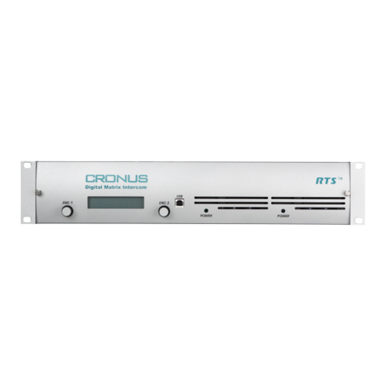
FIGURE 31. Controls, Connections, and Cronus backcard. There are two Cronus backcards, an MDR backcard and an RJ-12 backcard. You can have up to four backcards installed on Cronus. You can have any combination of backcards on the Cronus, too (for example, you can have two RJ-12... - Page 9 LCD display showing menu options. There are two USBUSB connections on the Cronus; one on the front panel and one on the back panel (J7). Cronus system can use the USB port connect with a PC. This allows for the most flexibility when planning where to use the system.
-
Page 10: Cronus Gain Structure
Cronus Gain Structure Cronus Gain Structure. The table below shows the gain level adjustments for Cronus ADAM, and Zeus. FIGURE 32. Input Gain Output Gain MAX Audio Max Input Cross Point Max Audio Control Range Control Range Input Level Gain... -
Page 11: Specifications
J2: RS-232 (Debug) Specifications Pin 1 ..............Not Used Pin 2 ................GND Analog Inputs and Outputs Pin 3 ............... Input RS-232 Pin 4 ..............Not Used Signal Type ...............balanced Pin 5 ..............Not Used Nominal Level ............... 8dBu Pin 6 ..............Not Used Maximum Level............ - Page 12 15km nominal with single mode fiber cables. The fiber cable recommended for Cronus Single mode SM SC-SC Duplex type. Two SC-SC simplex pair will work, but you will have to verify which end to connect to each other.
- Page 13 MDR Connector Pin Number Port Function Pin Number Port Function Data + Data + Data - Data - Audio To Matrix + Audio To Matrix + Audio To Matrix - Audio To Matrix - Audio From Matrix + Audio From Matrix + Audio From Matrix - Audio From Matrix - Data +...
-
Page 14: Determining The Master System From The Slave Systems
Determining the Master System From the Slave Systems By default, Cronus is set to operate in stand alone mode. You will need a license file to link Cronus frames together. In order to link 2 or more Cronus systems together, each must have the optional linking firmware installed. To purchase the firmware, contact RTS sales. -
Page 15: Cronus System Diagram And Frame Cabling
Cronus System Diagram and Frame Cabling The Cronus Intercom System has four frames, one Master and three Slave stations (see system diagram on left) FIGURE 35. connected via coaxial cables (see cabling diagram at right). Each frame can support up to 32 ports, and each system can have a maximum of 128 ports (all four frames available). - Page 16 Cable drawings for PAP32, AZedit, Trunking and UIO-256/LCP-102. FIGURE 37.
-
Page 17: Default Jumper Settings For The Master Controller Board
Populate jumper across pins 2 and 3. Write Protect Flash Chips IC11 and IC12 (Config Populate jumper across pins 2 and 3. Flash) NOTE: If you have board 9030-7785-000, see “Cronus Master Controller Card 9030-7785-000” on page 91 for the Default Jumper settings. -
Page 18: Default Jumper Settings For The Cronus Aio Board
Default Jumper Settings for the Cronus AIO Board Cronus AIO Board 9030-7784-000 FIGURE 39. Jumper Description Default Setting 5 volt Power Isolation Populate Jumper across J1 Populate Jumpers across J2: Pins 5-6 DSP Debug Port Pins 7-8 Pins 9-10 Pins 11-12... -
Page 19: Cronus Menu Structure
Set Frame ID In a single frame Cronus system, the frame will always be Stand Alone (or the Master frame). In a multi-frame system, the first time Cronus is powered on, each frame will show as Frame 1 and will need to be configured, either manually or by autoconfig, to designate which frame it is. - Page 20 Use the ENC2 knob to adjust the OUT Gain. NOTE: You can change the gain levels in AZedit and see the results on Cronus almost immediately. For more information on gain levels, see Figure 32 on page 6. Vox Thresholds Vox Threshold is the level of audio at which a channel becomes active.
-
Page 21: Status Menu
Double-tap the ENC1 knob to exit the threshold set menu item. Port displays. Turn the ENC1 knob to Hold Time. Tap the ENC1 knob. Hold Time appears. Turn the ENC1 knob to set the hold time (up to 12.5 seconds). NOTE: Hold time is the amount of time the VOX will stay active on a port before closing the port. -
Page 22: Status, Crosspoints
FIGURE 40. Status, Frames Frames displays the status of each of the Cronus frames. It tells if the frame is still active or if it has been deactivated. Turn the ENC1 knob to scroll to Status. When Status is displayed, tap the ENC1 knob. -
Page 23: Status, Gpi Output
You should check the status of the Frame Clock and the Link to each frame. This is good for diagnostic troubleshooting. NOTE: Frame 1 (Master) will only show the Frame 2 status because it only connects to one other Cronus frame. Version, Intercom The Version, Intercom menu, displays the firmware version that is current on the intercom. -
Page 24: Cronus Menu System Quick Reference
Menu List - Tree Diagram FIGURE 41. On the front panel of the Cronus system, tap the ENC1 encoder knob. The word Status appears. Turn the ENC2 encoder knob clockwise to scroll forward or counter-clockwise to scroll backwards through the list of menus. -
Page 25: Cronus And Azedit
Cronus or AIO-16 at a preset threshold level, the audio lines are open for conversation between ports. With Cronus, you can set the Vox threshold from the front panel or you can set it through AZedit. In AZedit there are two ways to access the Vox Settings screen. -
Page 26: Accessing Vox
Accessing Vox To access the Vox Settings screen from the System menu, do the following: From the System menu in AZedit, select Vox. The Vox Settings Screen appears. NOTE: You can change the threshold levels and hold times of more than one port at a time by pressing the CTRL key and clicking the ports you want to change. - Page 27 SCREEN ITEM FIELD TYPE DESCRIPTION Threshold Adjust arrow keys Use the arrow keys to increase or decrease the vox threshold DOWN by.5 dB (-127 dB to 0.0 dB). You can see the level adjustments in the parameter display window (to the right). NOTE: You can select multiple ports to change at the same time.
- Page 28 Real-Time Changes Changes Vox and hold time dynamically on the connected device (Cronus or AIO- 16). NOTE: When making adjustments from the front panel of the Cronus take into consideration that AZedit has a 5 second display refresh rate which will cause a delay in what is seen in the application.
- Page 29 Supported? display column displays whether the port is attached to a device Supported? that supports Vox (either a Cronus or AIO-16 card). NOTE: Cronus and AIO-16 are the only devices, presently, that support Vox. When a green is displayed, the device supports Vox. When a red displayed, the device does not support Vox.
-
Page 30: Download Cronus License File
To link more than one Cronus system together, you must have linking software installed on the system (normally, this is loaded at time of purchase). If you are adding a Cronus Intercom System to an existing Cronus matrix, you may need to load a license file on your existing system. -
Page 31: Ethernet Setup For Cronus
The PC must be running version 2.06.07 or later of AZedit and have an Ethernet card installed. Verify Cronus is connected to the PC using either a USB (universal) or RS-232 (ADAM standard) cable. The USB drivers can be found in the AZedit software directory (C:\Telex\AZedit|V20701|USB). You may only use on USB connection (front panel or back panel) at a time. - Page 32 In the Connection area, select the Network radio button. In the IP Address field, either enter the Cronus IP Address you wish to connect with, or click the Search button. The search button scans the network for any Cronus devices. If multiple units are on the network, each will appear in the list.
-
Page 33: Download Firmware For Cronus
Download Firmware for Cronus When firmware is downloaded to Cronus, all the code is put on the Master Controller card. This includes code for the AIO cards. Therefore, because the Master Controller downloads the firmware for the system and the code for the AIO cards, the download time is extended while the Master Controller pushes the AIO code out to the appropriate cards. -
Page 34: Finding The Mac Address For Cronus
The download begins. Once the Download is finished, click OK. The Cronus firmware download is complete. This will take a minute or two depending upon the type of connection you use (network or serial). Verify the version upgrade in the Master Controller Version Information window. - Page 35 The Ethernet Setup screen appears. The MAC Address aappears at the bottom of the screen. NOTE: If you have multiple Cronus systems linked together, you will need to individually connect them to the PC to see the MAC address. You cannot look at multiple Cronus MAC Addresses at the same time.
-
Page 37: Final Assembly Drawing
Final Assembly Drawing Cronus Final Assembly - see Table 1, “Final Assembly,” on page 34 for descriptions to the corresponding numbers. FIGURE 42. - Page 38 Part No. MDR SCSI Front panel, Cronus 9070-7770-000 Coax Link Module Card Plate 9110-7784-008 Lens 9150-7770-000 Cronus Fiber Link Module PCB 9030-7827-000 Master Controller Assembly 9020-7770-000 Fiber Link Module Card Plate 9110-7784-011 Screw, FH, 6-32 x 3/8” LG. 51847-022 Fiber Link Module Cable Assy...
- Page 40 FIGURE 43. Wiring Diagram...
-
Page 41: Rvon-C
RVON-C RTS Voice Over Network for Cronus Description of the RVON-C Voice Over Network Card Installed directly into the Cronus Intercom frame, the RVON-C provides voice over IP (Internet Protocol) communications for ® the RTS Cronus intercom system. In general, voice over IP means sending voice information in digital form using discrete packets rather than the traditional telephone network. -
Page 42: Features
Features The RVON-C card is hot-swappable and installs in any available slot in a Cronus Intercom Installation System. It provides a single RJ-45 Ethernet connection for use with a 10 BASE-T or 100 BASE- TX network. It also has a DB-9 connection for an RS-232 or RS-485 pass-thru port. -
Page 43: Rvon-C Jumpers And Connections
DB-9 Serial Port via backcard DB-9 Pin Function RXD, RVON-C Received Data TXD, RVON-C Received Data Power.................................... 5W Typical Physical ................................8.25”W x 6.25”L RVON-C JUMPERS and CONNECTIONS A selectable RS-232/485 serial port is at connector J1 Serial (see Figure 45 on page 41) on the back card. Jumper connections on J10, J11, and J12 (on the front card, see Figure 44 on page 40.) select the signal mode on J1. - Page 44 Pin 1 J10, J11, and J12 Frontcard - RVON-C 9030-7835-000 FIGURE 44.
- Page 45 J1 Serial J2 Serial RVON-C Backcard FIGURE 45. RVON-C Backplate FIGURE 46.
-
Page 46: Installation Of The Rvon-C Card Into The Cronus System
• When inserting the RVON-C card into the Cronus system, make sure to insert it into a compatible backcard. If the card is inserted into a incompatible backcard, undesirable results can occur. -
Page 47: Switches And Connections
Switches and Connections IMPORTANT: You must remove the card from the frame in order to change any DIP switch settings on the front card, see Figure 47 on page 43. DIP Switch 1 Closed: Configuration via AZedit is disabled. Open: (Default) Configuration via AZedit is enabled Disables the configuration changes via AZedit. -
Page 48: Configuring The Rvon-C Card With Azedit
Configuring the RVON-C Card with AZedit Once the RVON-C card is inserted into the Intercom, AZedit will automatically recognize the card. NOTE: Requires intercom firmware and AZedit software that support RVON cards. To configure the RVON-C card, do the following: From the Status menu, select I/O cards. - Page 49 Right-click on an RVON-C card, and select RVON-C Configuration. The RVON-C Configuration screen appears. From the RVON-C drop down list, select the slot in which the RVON-C card resides, if it is not already selected. In the IP Address field, enter the IP Address you have assigned to the RVON-C card. In the Network Mask field, enter the Network Mask to which the RVON-C card is connected.
- Page 50 NOTE: A CODEC is an algorithm used to compress audio. There are 5 Codices support by Telex: G.711μs law, G.711A law, G.729AB, G.723 (5.3k) and G.723 (6.3k). The type of CODEC will dictate the quality of audio you hear and the network bandwidth used.
-
Page 51: Rvon-C Connection Status Screen
RVON-C Connection Status Screen The RVON-C Connection Status screens display information pertaining to RVON-C channel connections. You can only show statistics for one channel on a card at a time. NOTE: To view the RVON-C Connection Status screens make sure both AZedit and the RVON-C card are on the same Ethernet network. - Page 52 Screen Item Description Select Local Card and Channel The card for which you want to view the status. RVON Card From the RVON drop down list, select the card you want to view. IP Address Displays the IP (Internet Protocol) Address of the card you select One of eight audio channels supported by the RVON-C card.
- Page 53 Screen Item Description The number of times a call attempt has been made and dropped. Attempts / Drops NOTE: The number of attempts should always be one greater than the number of drops. Current Call State Displays the state of connection. There are two connection states: Connected or Idle. Displays which end of the connection originated or terminated the call.
- Page 54 Screen Item Description VoIP Playout Statistics Displays how much audio can be received from the network before packets are lost. This is four Playout Buffer Size times bigger than configured packet size. This is a static system setting. Nominal Playout Displays how much audio is collected before playout begins.
- Page 55 Screen Item Description Network Statistics Voice Playout Packets Displays the number of voice packets transmitted and received from the other side of the (Tx/Rx) connection. Displays the number of DTMF (dual tone multiple frequency) relay packets transmitted and DTMF Relay Packets received.
- Page 56 Screen Item Description Error Counts Invalid Headers Displays how many IP packets could not be parsed. Invalid MAC Address Displays how many invalid MAC addresses tried to connect. Invalid SSRC Displays the number of packets with an invalid SSRC. Invalid Payload Displays how many incorrectly formatted packets were received.
- Page 57 Screen Items Description SERIAL TO The Serial to Ethernet information shows the serial data that is received on the serial connection ETHERNET and transferred to the Ethernet address of the card to which the serial data is sent. Bytes Transferred Displays the number of bytes transferred from the serial connection to Ethernet.
-
Page 58: View Rvon-C Status From Cronus Front Panel
If you have more than one Cronus linked together, the slots will continue numbering slot 5, slot 6, and so on. Turn the selector knob to select the desired slot. - Page 59 RVON-C Status Descriptions TABLE 2. ACTION DISPLAY When Ethernet is selected: Link Up - Displays whether the Ethernet link is active or inactive. Link Up=Active, Link Down=Inactive Speed - Displays the connection speed in mbps. Can be either 10mbps or 100mbps. Mode - Displays whether the connection is Half Duplex (data that moves in one direction) or Full Duplex (data that moves in both directions).
-
Page 60: Download Rvon-C Firmware Through Azedit
Download RVON-C Firmware through AZedit NOTE: AZedit sends the program directly to the RVON-C card over Ethernet. This is different from other I/O cards that receive the firmware from the Master Controller. For this reason, verify the PC running AZedit is on the same network as the RVON-C card. - Page 61 Click Open. The Download Device Firmware window appears. Click Begin Download. The download begins. Click OK. The RVON-C firmware download is complete. This may take a minute or two to occur. Verify the version upgrade in the I/O Card Version Information Window is correct. WARNING: Do NOT reset the Master Controller.
- Page 62 RVON-C System Diagram FIGURE 48.
-
Page 63: Basic Network Configuration
Appendix A Basic Network Configuration Basic Network Configuration This section covers basic network configuration set-up and testing. Also covered are basic concepts and operations, including the difference between LAN and WAN networks and how IP Addressing is used. In a networked environment, such as a company, typically there are many computers connected together using a router or a switch. -
Page 64: Wide Area Network
Local Area Network Diagram FIGURE 49. WIDE AREA NETWORK A WAN (Wide Area Network) connects two or more LANs and can span a relatively large geographical area. For example, Telex Headquarters in Burnsville, MN is connected to several branch offices in Nebraska and Arkansas over a WAN. The WAN in existence is the Internet. -
Page 65: Accessing The Wide Area Network (Wan)
ACCESSING THE WIDE AREA NETWORK (WAN) Figure 13 shows LAN IP Addresses using a common IP Address, 10.2.100.X (192.168.X.X is another common address). Most devices are shipped with these addresses as its default. It is recommended to use these addresses for LANs. Network Address Translation Figure 3. - Page 66 Packet Translation Table 2. Packet before Translation Packet After Translation Source Destination Source Destination Port Port Port Port IP Address IP Address IP Address IP Address Number Number Number Number 10.2.100.1 1031 192.156.136.22 99.5.1.30 1032 192.156.136.22 Internet From 192.156.136.22 99.5.1.30 1032 192.156.136.22 10.2.100.1...
-
Page 67: Ip Addresses
IP ADDRESSES ® If you do not know your IP Address, you can open a DOS screen in a Windows - based environment and bring up the ipconfig screen. To find your IP Address using ipconfig, do the following: From the Start Menu, open a Command Prompt screen. At the prompt, type ipconfig, then press Enter. -
Page 68: Ping A Computer
Ping a Computer Pinging a computer on the network makes sure it is able to be “seen” and receive messages on the network. NOTE: You can also ping your RVON-8 card to verify that it is responding over the network by putting the cards IP Address in place of the computer IP Address. - Page 69 To view the path an IP Address takes to retrieve information, you can execute a tracert from the Command Prompt Screen. To run a tracert, do the following: From the Start Menu, open a Command Prompt screen. At the prompt, type tracert and type the url or IP Address you want to trace. Press Enter.
-
Page 70: Rvon Configuration
RVON Configuration RVON cards use ports for communication of audio and control packets. Because routers can be configured to block certain incoming and outgoing requests, you will need to open the following ports in your network to allow WAN connections to and from a Network Interface Device. -
Page 71: Network Terminology
Network Terminology A bridge is a device that connects two LANs, or two segments of the same LAN that use the same protocol. Sometimes called “transparent bridges, they work at the OSI model Layer 2. Simply put, they are not concerned with protocols. Their main job is to pass data to a destination address that is predetermined in the data packet. - Page 72 A LAN is a computer network that connects a relatively small area (a single building or group of buildings). Most LANs connect work stations and computers to each other. Each computer (also known as a “node”), has its own processing unit and executes its own processing unit and executes its own programs;...
-
Page 73: Rvon-C Card
Appendix B RVON-C Card Serial Port Programming RVON Serial and Telnet Commands RVON-C card programming can be done via direct serial or telnet connection. There are several physical connections to an RVON-C card. • Direct serial through custom debug cable (J7 6-pin bottom front) The customer debug cable always functions as the general -purpose debug tool. -
Page 74: Rvon-C Boot Download
RVON-C Boot Download ***************************** RVON-C Revision 1.00.02 (C) Copyright 2003 Telex Inc. All Rights Reserved. Flash File System initialized. DIP Switch settings:..XXXX Configuration via AZedit disabled (via DIP Switch 1 on) Back card UART enabled for pass-through serial (via DIP Switch 6 off) Boot downloader disabled (via DIP Switch 7 off) Autoload enabled (via DIP Switch 8 off) Monitor Revision... - Page 75 appCreate: autoBootLevel=2 MXP environment is created. Creating RVON application... -> Bringing DSP subsystem out of reset... DSP Daughtercard type is set to NONE - No DSP Daughtercard Found 0000004883 - ROOT: FPGA Version = ff00 0000004890 - ROOT: Channel 2 Remote IP Address is unconfigured 0000004892 - ROOT: Channel 3 Remote IP Address is unconfigured 0000004894 - ROOT: Channel 4 Remote IP Address is unconfigured 0000004895 - ROOT: Channel 5 Remote IP Address is unconfigured...
-
Page 76: Access Serial Command Mode
Access Serial Command Mode There are many different serial port commands supported from here, but it is NOT recommended that any be used except: dbgcmd At a DOS prompt, type “dbgcmd”, then press Return. This places the serial port into the MXP> (MXP command mode). The MXP Command Mode is the only mode used. The table below is a list of commands supported from the MXP Shell Prompt. -
Page 77: Serial Command Table
Serial Command Table Serial Command Table TABLE 4. Command Variable 1 Variable 2 Description Help screen which lists all “set rvon” set rvon commands. set rvon ip_addr X.X.X.X Set the IP Address for the RVON Card. set rvon netmask X.X.X.X Set network mask for the RVON Card. - Page 78 Serial Command Table TABLE 4. Command Variable 1 Variable 2 Description Must do an activate command to cause changes activate to take effect. show rvon Display current settings show serial Display current settings show channel Display current settings [chan] show emac Display current settings...
-
Page 79: Codec Specifications
Codec Specifications Codec Specifications Figure 5. 0,3,6,9 G.711 100.00 14000 1,4,7,10 G.711 50.00 11000 2,5,8,11 G.711 33.33 10000 12,16 G.729 100.00 7000 13,17 G.729 50.00 4000 14,18 G.729 25.00 2500 15,19 G.729 16.67 2000 20,22 G.723 5.3k 33.33 2800 22.4 44.8 24,26 G.723... -
Page 80: Rvon-C Default Setup
RVON-C Default Setup Every attempt is made to ensure the board is shipped from the factory containing the following: All are “set rvon” commands VARIABLE ENVIRONMENT NAME DEFAULT DESCRIPTION VALUE ip_addr EMACA_IPADDR x.x.x.x IP Address for the RVON-C Card netmask EMACA_NETMASK 255.255.255.0 Network Mask for the RVONC card... -
Page 81: Rvon-C Quick Start
• When inserting the RVON-C card into Cronus, be sure to insert it into a compatible back card. If the card is inserted into an incompatible back card, undesirable results can occur. -
Page 82: Launch Azedit And Connect To The Cronus Frame
Launch AZedit and Connect to the Cronus Frame NOTE: You can connect to Cronus using Serial, USB, or Network Connections. The following instructions show how to connect using a Network connection. For more information on configuring the network connection for the Cronus, see page 27. -
Page 83: Configure The Rvon-C Card
You will now see CRONUS in the lower right hand corner of the AZedit application. Configure the RVON-C Card Once you have a connection to Cronus, you are now ready to configure the RVON-C card within the Cronus system. To configure the RVON-C card, do the following: From the Navigation bar at the bottom of the AZedit application, click the RVON button. - Page 84 In the Network Mask field, enter the Network Mask of the network to which the RVON-C card is connected. In the Default Gateway field, enter the Default Gateway Address (if applicable) of the network to which the RVON- C card is connected. A Default Gateway is only required if the RVON-C connections are between LANs or WANs.
-
Page 85: Configure The Devices Connected To The Rvon-C Card
• For RS485, jumper pins 1 & 2 of J10, J11, and J12 Once you have set the correct configurations, replace the RVON-C into Cronus and hook the DB-9 connector to the RVON-C backcard. To use the Serial connection, do the following: Set DIP Switch 6 to the CLOSED position. -
Page 87: Breakout Panels
Cronus MDR Audio from Matrix + backcard: XCP-32-DB9, XCP-48-RJ45, and XCP-48-Telco. On the Cronus you can have up to four MDR backcards Audio from Matrix - mounted on the chassis to give you that many more keypanel ports. -
Page 88: Xcp-32-Db9 Breakout Panel
DB9 breakout panel with MDR connecotr for the AIO- PORT FUNCTION Number 16. It allows you to expand the number of DB-9 serial ports on the Cronus. Data - Audio to Matrix + NOTE: When using the 32-port DB-9 breakout panel,... - Page 89 PORT FUNCTION Number Data + Data - Audio to Matrix + Audio to Matrix - Audio from Matrix + Audio from Matrix - NOTE: There are 4 MDR connectors on the XCP-32- DB9 Breakout Panel. MDR Connector Port 9-16 17-24 25-32 Description Pin 1...
-
Page 90: Xcp-48-Rj45 Breakout Panel
Pin Number Port Function The XCP-48-RJ45 is the newly created 48-port RJ45 breakout panel with MDR connector for the Cronus. It Data + allows you to expand the number of RJ-45 ports on the Data - ADAM system, up to 48 ports. - Page 91 Pin Number Port Function Data + Data - Audio to Matrix + Audio to Matrix - Audio from Matrix + Audio from Matrix - NOTE: There are 6 MDR Connector on the XCP-48 Telco Breakout MDR Connector port 41-48 33-40 25-32 17-24 9-16...
-
Page 92: Xcp-48-Telco Breakout Panel
The XCP-48-Telco is the newly created breakout panel with Pin Number Port Function MDR connector for the Cronus. It combines audio to matrix, audio from matrix, and data pairs. It then routes them on Data + individual Telco connectors. Data -... -
Page 93: Telco Backcard
Pin Number Port Function Port Function Number Audio to Matrix - Data + Data - Audio to Matrix + Audio to Matrix + Audio to Matrix - Audio to Matrix - Audio to Matrix + Audio from Matrix + Audio to Matrix - Audio from Matrix - Audio to Matrix + NOTE:... - Page 94 Port Function Number Audio to Matrix + Audio to Matrix - Audio to Matrix + Audio to Matrix - Telco Backcard Connector (J1, J4) Table 6.
-
Page 95: Cronus Master Controller Card
Appendix E Cronus Master Controller Card 9030-7785-000 Legacy Master Controller Card Jumper Settings Legacy Master Controller Card FIGURE 54. - Page 96 CONNECTOR DESCRIPTION DEFAULT SETTING J3 & 4 J Tag Connector and Flash Write Protect Populate across pins 1 & 2 and 9 & 10 Cold Fire Test Mode +5 Volt Jumper Populate across pins 1 & 2 44k / 48k mode select J Tag Mode Populate across pins 2 &...
-
Page 97: Notes
Notes Notes... -
Page 99: Rvon Trunking Connections
In this chapter you will find the following drawings: • AZedit Via RVON-8 RS-232 Mode • CS9500 Trunking Via RVON-I/O To RVON-8 • ADAM Trunking Via RVON-8 • Zeus II Trunking Via RVON-I/O To RVON-C • Cronus Trunking Via RVON-I/O To RVON-8... - Page 101 Figure 7: AZedit Via RVON-8 RS-232 Mode...
- Page 102 Figure 8: CS9500 Trunking Via RVON-I/O To RVON-8...
- Page 103 Figure 9: ADAM Trunking Via RVON-8...
- Page 104 Figure 10: Zeus II Trunking Via RVON-I/O to RVON-C...
- Page 105 Figure 11: Cronus Trunking Via RVON-I/O To RVON-8...
- Page 106 Figure 12: RVON-16 Trunking...
-
Page 107: Notes
Notes...