
Related Manuals for RTS ODIN


Summary of Contents for RTS ODIN
- Page 1 ODIN OMNEO Digital Intercom up to and including version 1.1.0 Rev. 03 05/2019 F.01U.345.086...
- Page 2 For warranty and service information, refer to the appropriate web site below: WARNING: THE MAIN POWER PLUG MUST REMAIN READILY OPER- ABLE. RTS Intercoms ......www.rtsintercoms.com/warranty RTS Digital CAUTION: TO REDUCE THE RISK OF ELECTRIC SHOCK, GROUNDING RTSTW OF THE CENTER PIN OF THIS PLUG MUST BE MAINTAINED.
- Page 3 ODIN Intercom Important Safety Instructions Read these instructions. Keep these instructions. Heed all warnings. Follow all instructions. Do not use this apparatus near water. Clean only with dry cloth. Do not block any ventilation openings. Install in accordance with the manufacturer’s instructions.
- Page 4 ODIN Intercom...
-
Page 5: Table Of Contents
Table Contents INTRODUCTION .........................9 Features ..............................9 Reference View – ODIN Front Panel ....................10 Reference View – ODIN Rear Panel .....................11 Specifications ............................12 Connections ............................14 Connector Pinouts ..........................14 Licensing ..............................16 ODIN System Descriptions ........................16 Single-Frame System ..........................16 Multi-Frame System ..........................17 BASIC OPERATION .........................19... - Page 6 ODIN Intercom Matrix Network Port Cabling ..........................52 Network Port Configuration ........................52 Intercom Configuration ..........................55 Rack Mounting Instructions ........................65 GPIO 24-Position Terminal Block Connector ..................68 Fan Tray ..............................69 FIRMWARE ..........................73 Download Firmware ..........................73 Download a Splash Screen, Screen Saver or Licenses ................77 Request Frame Identification .........................78...
- Page 7 ODIN Intercom Matrix System Menu ..........................114 Add Frames..........................120 Remove Frames ........................122 Split Intercom ........................123 Frame Mapping Table ......................124 Port Allocation Table......................125 Intercom Name ........................126 Network Menu..........................127 Control Port ...........................127 OMNEO..........................128 RVON............................129 Management Port........................129 Ports Menu...........................130 OMNEO Channels.........................130 RVON Channels ........................131 2-Wire Ports...........................132...
- Page 8 ODIN Intercom Matrix Crosspoint ..........................159 Party Line ..........................159 Alphas Menu..........................160 Alphas ............................160 Alarms Menu ............................162 Unacknowledged .........................162 Active............................163 Notes ..............................165...
- Page 9 FIGURE 11. Status Menu Icons ......................82 FIGURE 12. Status | System Menu Items ....................82 FIGURE 13. Status | System | ODIN Versions ..................82 FIGURE 14. Status | System | AZedit Sessions ..................83 FIGURE 15. Status | System | IPedit Sessions ..................83 FIGURE 16.
- Page 10 ODIN Intercom Matrix FIGURE 41. Status | Hardware | Power Supplies .................110 FIGURE 42. Status | Hardware | Cooling Fans ..................111 FIGURE 43. Status | Hardware | Temperatures ..................112 FIGURE 44. Status | Hardware | Clock ....................113 FIGURE 45. Configuration Menu Icons ....................114 FIGURE 46.
- Page 11 ODIN Intercom Matrix FIGURE 92. Intercom Setup | Resources | Party Line .................153 FIGURE 93. Intercom Setup | Resources | IFB ..................154 FIGURE 94. Intercom Setup | Resources | Special List ...............155 FIGURE 95. Intercom Setup | Resources | Relay .................156 FIGURE 96.
- Page 12 ODIN Intercom Matrix...
-
Page 13: Introduction
The ODIN Digital Intercom is a highly scalable intercom system in a 1RU (Rack Unit) package. As the capacity needs evolve, a single ODIN can grow from 16 ports to a maximum of 128 ports. Up to eight ODIN frames can be interconnected via optical Inter- Frame Links creating a single intercom with up to 1024 ports. -
Page 14: Reference View - Odin Front Panel
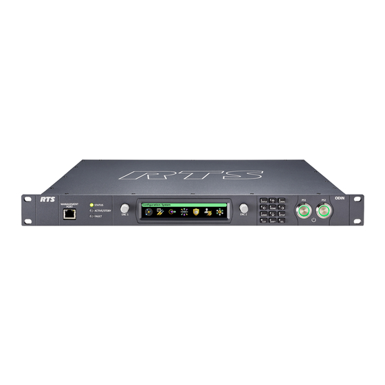
10 Introduction ODIN Intercom Matrix Reference View – ODIN Front Panel ODIN Front Panel FIGURE 1. Status, Active/Stdby, and Fault LEDs High resolution LCD display Keypad Management port - Ethernet connector (See “Management Port - RJ-45 Supports 10/100/1000 Ethernet” on page 14) -
Page 15: Reference View - Odin Rear Panel
ODIN Intercom Matrix Introduction 11 Reference View – ODIN Rear Panel ODIN Rear Panel FIGURE 2. PS 1 – AC power connector PS 2 – AC power connector AIO analog connectors – 16x (See “AIO Connector (RJ-45): J4 - x16” on page 14) 2W party line CH A and CH B –... -
Page 16: Specifications
12 VDC (Clear-Com mode) disconnect AC from the internal power supplies. MIC KILL Signaling ........24 kHz (RTS mode) Power cords must be fully removed from frame to safely disengage internal power. - Page 17 ODIN Intercom Matrix Introduction 13 Control Port: Agency Compliance: Connector ................RJ-45 Emissions (Class A) Format ............IEEE 802.3 compliant EN 55032:2012/AC:2013 • Speed ..............10/100/1000 Mbps KN32 w RRA Public Notification 2016-26 & RRA LEDs .............Speed and Link/Activity • Announce 2016-79...
-
Page 18: Connections
Audio Low Audio network. Each RJ- (Optional +30 V) (+24 V) 45 Ethernet connector has two a. ODIN does not supply power. LEDs: Left LED. The left AIO Connector (RJ-45): J4 - x16 LED is yellow and indicates a network Assignment link is established. - Page 19 ODIN Intercom Matrix Introduction 15 CONTROL & RVON: J8 GPIO Connector: J5 Ethernet x 2 Assignment Silk Screen Assignment RELAY1_COM Data 1 + RELAY1_NC Data 1 - RELAY1_NO Data 2 + RELAY2_COM Data 3 + RELAY2_NC Data 3 - RELAY2_NO...
-
Page 20: Licensing
For more information, see “Download a Splash Screen, Screen Saver or Licenses” on page 77. ODIN System Descriptions Single-Frame System ODIN can connect to keypanels via OMNEO, RVON, and AIO. Up to 16 analog panels can be directly connected via the AIO ports on the back of each ODIN frame.. Single-Frame System... -
Page 21: Multi-Frame System
ODIN Intercom Matrix Introduction 17 Multi-Frame System For more information, see “IFL Inter-Frame Linking (Multi-Frame Only)” on page 41. Multi-Frame System FIGURE 4. - Page 22 18 Introduction ODIN Intercom Matrix...
-
Page 23: Basic Operation
Basic Operation Navigating the Menu The ODIN menu structure is separated into four logical sections: Status, Configuration, Intercom Setup, and Alarms. The menu is accessible using the keypad, the shaft encoder knobs, or a combination of both. ODIN Keypad and Encoders FIGURE 5. -
Page 24: Editing Form Data
20 Basic Operation ODIN Intercom Matrix Shaft Encoder Operation Action/Mode Home Port Status Menu Form (navigating) Form Overview (navigating) + SHIFT) Click Go to STATUS Go to HOME screen Move up one level Exit form (prompt if overview changes) Double Click... - Page 25 ODIN Intercom Matrix Basic Operation 21 NOTE: Pressing CLR does a backspace if the cursor is not at the start of a field. At the start of a field, CLR deletes • the character at the cursor. Press CLR when there is no text in the field aborts the changes.
-
Page 26: Odin Icon And Menu Descriptions
ODIN Icon and Menu Descriptions Display Panel Icons Display Panel Icons are used to navigate the menu structure on the ODIN frame. Use Table 1 for a complete description of each icon seen in the menu and submenu structure. Display Icon Description and Menu Structure TABLE 1. - Page 27 ODIN Intercom Matrix Basic Operation 23 Display Icon Description and Menu Structure TABLE 1. Icon Icon Name Description OMNEO (RJ-45) The OMNEO (RJ-45) menu item displays status details for the OMNEO RJ-45 ports. For more information, see “OMNEO (RJ-45)” on page 87.
- Page 28 24 Basic Operation ODIN Intercom Matrix Display Icon Description and Menu Structure TABLE 1. Icon Icon Name Description The Peripherals menu item is used to select the peripheral status to be Peripherals viewed. For more information, see “Peripherals Menu” on page 97.
- Page 29 ODIN Intercom Matrix Basic Operation 25 Display Icon Description and Menu Structure TABLE 1. Icon Icon Name Description The IFL menu item displays status details for IFL connections. For more information, see “IFL” on page 107. Hardware The Hardware menu item is used to select the hardware status to be viewed.
- Page 30 26 Basic Operation ODIN Intercom Matrix Display Icon Description and Menu Structure TABLE 1. Icon Icon Name Description Add Frames The Add Frames menu is used to add a new frame to an existing intercom by connecting a new frame via IFL. The Frame Mapping Table is updated automatically and a new system size is automatically determined (but may be modified by the user before being applied).
- Page 31 The GPIO-16 menu item is used to configure the GPIO-16 for use in the intercom system. For more information, see “GPIO-16” on page 134. The Authentication menu is used to select different areas of the ODIN Authentication system to configure security.
- Page 32 28 Basic Operation ODIN Intercom Matrix Display Icon Description and Menu Structure TABLE 1. Icon Icon Name Description AZedit The AZedit menu item is used to restrict access to AZedit. For more information, see “AZedit” on page 135. IPedit The IPedit menu item is used to restrict access to IPedit.
- Page 33 Options The Options menu item is used to access the Options configuration form. This form is used to define how ODIN constructs work on the frame. For more information, see “Options” on page 142. The Advanced menu is used to select advanced configuration options to Advanced modify.
- Page 34 The Stored Setup Slot files are used to store, modify, or delete intercom setup files. Up to four stored setups (Slots) can be configured and saved in ODIN. Keypanels The Keypanels menu is used to select the various keypanel setup options such as Key Assignments, Setup Pages, and Scroll Enables.
- Page 35 ODIN Intercom Matrix Basic Operation 31 Display Icon Description and Menu Structure TABLE 1. Icon Icon Name Description The IFB menu item is used to configure IFBs. For more information, “IFB” on page 154. Special List The Special List menu item is used to configure special lists.
- Page 36 32 Basic Operation ODIN Intercom Matrix Display Icon Description and Menu Structure TABLE 1. Icon Icon Name Description Party Line The Party Line menu item is used to view and edit the Alpha(s) and Scroll Enable flags for each party line assignment.
-
Page 37: Front Panel Overview And Operation
ODIN Intercom Matrix Basic Operation 33 Front Panel Overview and Operation Management Port The Management Port is a front-panel Ethernet interface, providing convenient access for a laptop running AZedit. Access to the Management Port can be enabled or disabled via the Authentication menu item, see “Management Port” on page 138. -
Page 38: Port Status Overview
34 Basic Operation ODIN Intercom Matrix Port Status Overview The Port Status Overview displays the port status in each frame of the intercom. The port type and port status are represented by different colored status boxes. To display the port status screen, do the following: While on the Home Screen, click the left encoder knob. -
Page 39: Link Status Overview
ODIN Intercom Matrix Basic Operation 35 Link Status Overview The Link Status Overview screen is used to view the different system connections available on ODIN. The connection status is represented by different colored LEDs. Link Status Overview FIGURE 8. Ethernet The Ethernet section displays link status for CTRL, RVON, MGMT, and OMNEO (4) ports. -
Page 40: Ifl/F2F
36 Basic Operation ODIN Intercom Matrix IFL/F2F The IFL/F2F section displays the IFL link status and the Frame to Frame link status. For single frame configuration, this section is labeled IFL, the F2F label is only displayed in a multi-frame system. -
Page 41: Misc
ODIN Intercom Matrix Basic Operation 37 Misc. The Misc. section contains additional status information for Alarms, AZedit sessions, IPedit sessions, PTP clock stats, and TM status. For Alarms X/Y is shown, where X is the number of unacknowledged alarms and where Y is the total number of active alarms. -
Page 42: Intercom Port Allocation
Physical hardware, such as AIO and 2-wire devices, and network port devices, such as RVON and OMNEO, can be mapped to any port in the intercom. For more information, see “Port Allocation Table” on page 125. For more information on IFL Interconnection Schemes, see the Interconnecting ODIN Frames application guide. Allocate Ports from the Front Panel of ODIN To allocate ports from the front panel of ODIN, do the following: Rotating the right encoder knob, navigate to the Configuration icon. - Page 43 ODIN Intercom Matrix Basic Operation 39 Click the right encoder knob. The Type field becomes active. Rotating the right encoder knob, select the desired assignment type (for example, AIO, 2W, OMNEO, RVON or <none>). Click the right encoder knob to confirm the selection.
- Page 44 40 Basic Operation ODIN Intercom Matrix Allocate Ports in AZedit To allocate ports using AZedit, do the following: From the Options menu, select Port Allocation Table. The Port Allocation Table window appears. NOTE: When Port is unlicensed is seen in the port allocation table, it means the port is not licensed for use and cannot be configured.
-
Page 45: Ifl Inter-Frame Linking (Multi-Frame Only)
Frame Only) IFL (Inter-Frame Linking) is a system configuration in which multiple ODIN frames operate as a single intercom matrix. Using fiber optic IFL cables, up to eight ODIN frames can be inter-connected. NOTE: Although IFL is only used for connecting two or... - Page 46 42 Basic Operation ODIN Intercom Matrix Cabling IFL Between Two ODIN Frames For a redundant connection To set up a 2-frame IFL system, do the following: On the rear panel of frame 1, connect one end of a second IFL cable to the SEC DOWNLINK On the rear panel of frame 1, connect one end of an connector.
- Page 47 Cabling IFL Between Three Or More ODIN Frames Ring architecture is used when connecting three or more (up to a maximum of eight) ODIN frames via IFL. In a ring-wiring architecture, each frame has links to two other frames. These...
- Page 48 44 Basic Operation ODIN Intercom Matrix For A Redundant Connection IMPORTANT: IFL connection redundancy does not mean the frame and its setup is redundant. Only the connection between frames is protected from cable failure. On the rear panel of frame 1, connect one end of an IFL cable to the PRI DOWNLINK connector.
- Page 49 ODIN Intercom Matrix Basic Operation 45...
- Page 50 46 Basic Operation ODIN Intercom Matrix Checking the IFL Status (Front Panel) To display the IFL connection status from the front panel, do the following: Rotating the right encoder knob, navigate to the Status icon. Click the right encoder knob.
- Page 51 ODIN Intercom Matrix Basic Operation 47 Checking the IFL Status (AZedit) To check the IFL Status from AZedit, do the following: From the Status menu, select Inter-Frame Link. The IFL Status window appears.
-
Page 52: Frame Mapping (Multi-Frame Only)
To order the frames in a system, a frame mapping table must be configured. Frame mapping can be done from either the front panel of ODIN or by using the AZedit configuration software. Frame Mapping (Front Panel) To map frames from ODIN front panel, to the following: Rotating the right encoder knob, navigate to the Configuration icon. Click the right encoder knob. - Page 53 ODIN Intercom Matrix Basic Operation 49 Frame Mapping (AZedit) To map frames from AZedit, do the following: From the Options menu, select Frame Mapping. The Frame Mapping Table window appears. Click the Browse icon to select frame to add to the table.
-
Page 54: Rstp
50 Basic Operation ODIN Intercom Matrix Click Done. The Frame Mapping Table window closes. Move Up/Move Down Button The Move Up and Move Down button is used to set the frame order in the system. The order in which the frames are set determines the ports that are assigned to each frame. -
Page 55: Installation And Maintenance
Installation and Maintenance Introduction The ODIN Digital Intercom is a highly scalable intercom system in a 1RU (Rack Unit) package. Up to eight ODIN frames can be interconnected via optical Inter-Frame Links creating a single matrix with up to 1024 ports. -
Page 56: Network Port Cabling
Network Port Cabling To cable ODIN to a network, do the following: On the rear panel of ODIN, connect an Ethernet cable to the J8 CONTROL connector. If using OMNEO over Ethernet, connect an RJ-45 cable to the J10 OMNEO PRI(RJ-45) connector. - Page 57 ODIN Intercom Matrix Installation and Maintenance 53 Configure the Control Port Interface The Control Port screen is used to configure the network interface used for AZedit, Trunk Master, and frame-to-frame communications in multi-frame systems To configure the Control Port interface, do the following: Rotating the right encoder knob, navigate to the Control Port icon.
- Page 58 In the Audio IP field, enter the IP address used to transmit and receive audio across the network. NOTE: The Audio IP address and the Control IP address should be in the same subnet. ODIN displays a warning message if these addresses are not on the same subnet.
-
Page 59: Intercom Configuration
(for analog ports) to specific intercom ports. Analog port devices, such as AIO and 2-wire devices, and network port devices, such as OMNEO, can be mapped to any port in the intercom. To allocate ports from the front panel of ODIN, see “Allocate Ports from the Front Panel of ODIN” on •... - Page 60 (for example, if the user is not ready to Save or Discard the modifications). On the back of ODIN, connect the 2W device to the CH A or CH B connector configured in the Port Allocation Table. Connecting Analog Keypanels to ODIN To connect an analog keypanel to ODIN, do the following: Using the Port Allocation table, assign the device channel to the AIO port.
- Page 61 Connecting OMNEO devices to ODIN To connect OMNEO devices to ODIN, do the following: Using the Port Allocation table, assign the device channel. See “Allocate Ports from the Front Panel of ODIN” on page 38. Rotating the right encoder knob, navigate to the Configuration icon.
- Page 62 Connecting RVON Devices to ODIN To connect RVON devices to ODIN, do the following: Using the Port Allocation table, assign the device channel. See “Allocate Ports from the Front Panel of ODIN” on page 38. Rotating the right encoder knob, navigate to the Configuration icon.
- Page 63 The RVON Channels screen appears. IMPORTANT: If the intercom system contains only one ODIN frame, the Frame field is not displayed. If the intercom system contains multiple ODIN frames, the Frame field activates allows ports in other frames to be selected and configured.
- Page 64 (in which case an IPedit session needs to be run on each network and each session sees either ODIN or ODIN-R, but not both), unless the PC has two network cards (one on each network) or the two networks are routable via a gateway.
- Page 65 The Destination Type does not need to be selected if using the Browse window to select the device. It fills the type and IP Address automatically. The type can be OKP, OKI, OEI, OAP, OMI, or another ODIN. Using the Channel Configuration Pane In the Destination Device Name field, click the ...
- Page 66 Configure an RVON Keypanel to connect to ODIN To configure an RVON keypanel to accept a connection offer from an ODIN intercom, do the following: On the keypanel, navigate to the RVON Offers | Keypanel menu, select the Matrix connection type you want to use.
- Page 67 NOTE: The Destination Type does not need to be selected if using the Browse window to select the device. It fills the type and IP Address automatically. From the Destination Channel drop down menu, select the channel to which ODIN connects. From the Coding Algorithm drop down menu, select the appropriate codec.
- Page 68 Map Multiple Frames in the System (Multi-Frame Only) Frame Mapping can be done from the front panel of ODIN or by using the AZedit configuration software. To map frames from the front panel, see “Frame Mapping (Front Panel)” on page 48.
-
Page 69: Rack Mounting Instructions
CAUTION: Ensure the frame is securely mounted to avoid uneven mechanical loading. Use all fasteners, as defined in the installation instructions. Rack Mounting (without Optional Rear Supports) To mount ODIN in a rack, do the following: Using four rack screws (not supplied), secure ODIN into the rack. > Rack Mounting (with Optional Rear Supports) Rear Rack Mounting Components IMPORTANT: The rear support brackets are an optional piece of equipment. - Page 70 Do not over-tighten the fasteners. Over-tightening can result in stripped or broken screws. Using the supplied flat-head screws (four on each side), secure the matrix side brackets to each side of the ODIN frame. NOTE: Take care to verify the guide pins on the side brackets face inward.
- Page 71 ODIN Intercom Matrix Installation and Maintenance 67 On both sides, pass the rear side brackets through the keyhole stand-off (1). Slide the rear side brackets until they reach the rear rack posts. Using four rack screws (not supplied), secure the rear side brackets to the rear rack posts.
-
Page 72: Gpio 24-Position Terminal Block Connector
68 Installation and Maintenance ODIN Intercom Matrix IMPORTANT: Layer the screw, the tooth lock washer and the flat washer in this order to attach the rear side bracket to the matrix side bracket. GPIO 24-Position Terminal Block Connector The GPIO 24-Position Terminal Block Connector is used to provide connections to relays (outputs) and opto-isolators (inputs). -
Page 73: Fan Tray
Using both thumbs, gently press down on the locking levers. > The connector is released from the frame. Fan Tray Fan Tray Side Panel of ODIN FIGURE 9. To replace the fan tray, do the following: Remove all power from the frame. - Page 74 70 Installation and Maintenance ODIN Intercom Matrix Carefully, slide the fan tray away from the frame and then lay the external face on a flat smooth surface. Unplug the five fan harnesses from the frame. IMPORTANT: Care must be taken to depress the locking feature (1) on each harness connector before disengaging. Wire and/or receptacle damage can occur if not properly removed.
- Page 75 ODIN Intercom Matrix Installation and Maintenance 71 Slide the new fan tray assembly into the frame. IMPORTANT: Take care that all wires are inside the frame. Replace the eight screws, securing the fan tray to the frame. NOTE: M3x6 flat-head screws are used Before mounting the unit back into the rack, power on the unit to verify the fans are working properly.
- Page 76 72 Installation and Maintenance ODIN Intercom Matrix...
-
Page 77: Firmware
CHAPTER 4 Firmware Download Firmware There are two processes for updating firmware and resources on ODIN; via AZedit or via the FWUT (Firmware Upload Tool). However, updating the Audio FPGA can only be done using the FWUT. Download Firmware Using AZedit To download firmware to ODIN, do the following: Open AZedit. - Page 78 Click OK. In the Master Controller Version Information window, verify the firmware upgrade. The flash programming progression status is shown on the front panel of the ODIN frame. NOTE: ODIN-Firmware.mot file contains six different components–Main firmware, main FPGA, LEC firmware, FP...
- Page 79 Download Firmware Using the Firmware Upload Tool The Audio FPGA can only be upgraded using the Firmware Upload Tool. NOTE: The ODIN-Firmware.capfw file includes all the components contained in the .mot file, plus the Audio FPGA. Required Firmware version: FWUT V5.4.0 and above...
- Page 80 Click the Start button. The Firmware Upload Tool main screen appears with a progression bar displayed. Once the Audio FPGA is downloaded, ODIN reboots and switches into bootloader mode automatically. In bootloader mode, the remaining firmware components are downloaded. Once finished downloading the remaining firmware, ODIN reboots automatically.
-
Page 81: Download A Splash Screen, Screen Saver Or Licenses
ODIN Intercom Matrix Firmware 77 Download a Splash Screen, Screen Saver or Licenses NOTE: When using a splash screen or screen saver the maximum bitmap size is 576 x 90. If the bitmap is smaller than the full screen dimensions, the front panel centers the bitmap horizontally and vertically on the display and fills the background with the same color as the pixel in the top left corner of the splash screen. -
Page 82: Request Frame Identification
The Request Frame Identification option is used to display the frame number on the front panel of the frame from AZedit. The display is more visible to see, for example from across a room. To have each ODIN frame in an intercom identify itself by displaying the frame number on the front panel, do the following: Open AZedit. - Page 83 Firmware 79 From the popup menu, select Request frame identification..All ODIN frames in the intercom display their frame number on the front panel. NOTE: A green popup appears on the frame which is connected to AZedit. On the other frames in the intercom, the...
- Page 84 80 Firmware ODIN Intercom Matrix...
-
Page 85: Menu System Description
If the intercom system contains only one ODIN frame, the Frame field is hidden. If the intercom system contains multiple ODIN frames, the Frame field is visible allowing the frame to be switched to alternate frames. While the Frame field is highlighted, press the right encoder knob to activate the field. -
Page 86: Status Menu
Peripherals Intercom Hardware System Menu The System menu contains information about the firmware used in ODIN, AZedit, and IPedit sessions currently running. Status | System Menu Items FIGURE 12. ODIN Versions The ODIN Versions screen displays the current versions for each firmware component in the system. -
Page 87: Azedit Sessions
ODIN Intercom Matrix Menu System Description 83 AZedit Sessions The AZedit Sessions screen displays the user name (login name), if applicable, and network connection (CTRL or MGMT Port) of each AZedit session connected to the frame. Status | System | AZedit Sessions FIGURE 14. -
Page 88: Network Menu
84 Menu System Description ODIN Intercom Matrix Network Menu The Network menu item is used to view information about the following network connections: Control Port OMNEO (SFP) OMNEO (RJ-45) RVON Management Port Status | Network Menu Icons FIGURE 16. Control Port The Control Port screen is used to view the control port network status information. -
Page 89: Omneo (Sfp)
ODIN Intercom Matrix Menu System Description 85 Speed Field The Speed field displays the transmission speed of the Control Port interface. There are three speeds the Ethernet links support: 10 Mbps, 100 Mbps, or 1 Gbps. Duplex Field The Duplex field displays the transmit mode the network connection is currently operating – Half or Full Duplex. Almost all Ethernet interfaces auto-negotiate to Full Duplex. - Page 90 SFP Installed Field The SFP Installed field displays whether or not the transceiver module is installed on ODIN. This field is directly tied to the Link Up field. If a transceiver module is not installed the OMNEO (SFP) port cannot be used.
-
Page 91: Omneo (Rj-45)
ODIN Intercom Matrix Menu System Description 87 OMNEO (RJ-45) The OMNEO (RJ-45) screen is used to view the status of the OMNEO (RJ-45) network status. Status | Network | OMNEO (RJ-45) FIGURE 19. Frame Field The Frame field is used to select the frame to be viewed. -
Page 92: Rvon
88 Menu System Description ODIN Intercom Matrix RVON The RVON screen is used to view the status of the RVON network status. Status | Network | RVON FIGURE 20. Frame Field The Frame field is used to select the frame to be viewed. -
Page 93: Management Port
ODIN Intercom Matrix Menu System Description 89 Management Port The Management Port screen displays the network status information for the Management Port. Status | Network | Management Port FIGURE 21. Frame Field The Frame field is used to select the frame to be viewed. -
Page 94: Ports
90 Menu System Description ODIN Intercom Matrix Ports The Ports menu is used to view port status for the following port and device types: OMNEO RVON 2-Wire Keypanel Status | Ports Menu Icons FIGURE 22. OMNEO The OMNEO screen displays the status for OMNEO ports. -
Page 95: Rvon
ODIN Intercom Matrix Menu System Description 91 Connected Field The Connected field is used to view the state of the connection. Typical states are Idle and Connected, however there can be transitional states during connection setup and tear down. The connection states available are Connected and Idle. - Page 96 92 Menu System Description ODIN Intercom Matrix Connected Field The Connected field is used to view the state of the connection. Typical states are Idle and Connected, however there can be transitional states during connection setup and tear down. The connection states available are Connected and Idle.
-
Page 97: Aio
ODIN Intercom Matrix Menu System Description 93 The AIO screen is used to display the AIO port status, which includes keypanel status and communication error counters. Status | Ports | AIO FIGURE 25. Frame Field The Frame field is used to select the frame to be viewed. -
Page 98: 2-Wire
6. The maximum displayed BER value is 255. 2-Wire The 2-Wire screen displays status information for the two connectors, CH A and CH B, located on the rear panel of ODIN. Status | Ports | 2-Wire FIGURE 26. Frame Field The Frame field is used to select the frame to be viewed. -
Page 99: Keypanel
PWR Field The PWR field indicates whether ODIN detects DC Power (for example, voltage) on the 2W line. In most systems, there is a power supply like a PS-20 on the 2W line which provides power to the beltpacks. This status indication could be useful to ensure that their system is set up correctly. -
Page 100: Tif
96 Menu System Description ODIN Intercom Matrix Connected Field The Connected field displays the status information of the connection. Available statuses are The panel is connected. The panel was connected, but is no longer connected. There is no connection. KP Type Field The KP Type field displays the type of keypanel connected to the intercom. -
Page 101: Peripherals Menu
ODIN Intercom Matrix Menu System Description 97 Status Field The Status field displays the status of the TIF. Available states are: Off-hook Ringing – (on-hook/idle) Peripherals Menu The Peripherals menu contains a list of the different types of peripheral devices available. - Page 102 98 Menu System Description ODIN Intercom Matrix TM Status Field The TM Status field displays whether a Trunk Master is connected to the system. Available statuses are The TM is connected. The TM was connected, but is no longer connected.
-
Page 103: Gpio-16
ODIN Intercom Matrix Menu System Description 99 Round Trip Field The Round Trip field displays approximately how long, in milliseconds, it take for a message from the intercom to be acknowledged by the trunk master. The round trip time reflects network delays. Since packets are not acknowledged immediately. The round trip time may be up to 50 mSec for local networks with low latencies. -
Page 104: Lcp-102
100 Menu System Description ODIN Intercom Matrix Status Field The Status field displays the GPIO-16 port communication status. The GPIO-16 is connected. The GPIO-16 was connected, but is no longer connected. There is no connection. Errors To/From Field The Errors To/From field displays the number of errors to and from the GPIO-16 logged by the intercom. -
Page 105: Pap-32
ODIN Intercom Matrix Menu System Description 101 Errors To/From Field The Errors To/From field displays the number of errors to and from the LCP-102 logged by the intercom. BER To/From Field The BER To/From field displays the number of errors to and from the LCP-102 in the last 10 minutes. -
Page 106: Pap-5032
102 Menu System Description ODIN Intercom Matrix PAP-5032 Status | Peripherals | PAP-5032 FIGURE 34. PAP-5032s Field The PAP-5032s field is used to select the PAP-5032 to view. The number of PAP-5032 allowed to select is directly related to the number of units defined in the Intercom Configuration screen (see “Reconfigure”... -
Page 107: Intercom Menu
ODIN Intercom Matrix Menu System Description 103 Intercom Menu Status | Intercom Menu FIGURE 35. GPIO The GPIO screen displays status information for General Purpose Inputs and Outputs in the intercom. Status | Intercom | GPIO FIGURE 36. GPIO Selection Field The GPIO selection field is used to select whether Input status or Output status is being displayed. -
Page 108: Crosspoint Inspect
104 Menu System Description ODIN Intercom Matrix Crosspoint Inspect The Crosspoint Inspect screen displays the crosspoint status for the selected input and output ports. Status | Intercom | Crosspoint Inspect FIGURE 37. Input Field The Input field displays the input port alpha. -
Page 109: Frame To Frame (Multi-Frame Only)
ODIN Intercom Matrix Menu System Description 105 Gain Field The Gain field displays the crosspoint gain. Path Gain Field The Path Gain field displays the overall gain that takes into account the input and output gains, as well as the crosspoint gain. - Page 110 106 Menu System Description ODIN Intercom Matrix Active Field The Active field displays whether or not the fiber link is active. The frame is connected. There is no connection. IP Address Field The IP Address field displays the IP address of the selected frame.
-
Page 111: Ifl
ODIN Intercom Matrix Menu System Description 107 Retransmits Field The Retransmits field displays approximately how many messages (for example, packets) needed to be retransmitted because no acknowledgement for those packets was received by the frame. Packets From Field The Packets From field displays the number of packets (for example, messages) sent from the selected frame and received by this frame. -
Page 112: Primary/Secondary Uplink/Downlink
Primary/Secondary Uplink/Downlink The Primary/Secondary Uplink/Downlink sections display the communication status of the connectors located on the back panel of the ODIN frame. Connected Field The Connected field displays the status of the IFL communication link between frames. - Page 113 Tx Messages Field The Tx Messages field displays the number of messages sent from the ODIN frame. To Link Field The To Link field displays the physical connection to which the frame is connected. For example, the Primary Uplink connector of the current frame would show it being connected to the Primary Downlink of the next frame in the system.
-
Page 114: Hardware Menu
110 Menu System Description ODIN Intercom Matrix Hardware Menu The Hardware menu is used to access the status of the different hardware in the ODIN frame, such as power supplies, cooling fans, temperature, and word clock. Status | Hardware Menu FIGURE 40. -
Page 115: Cooling Fans
Cooling Fans The Cooling Fans menu item displays fan readings for the frame. ODIN has five cooling fans located on the left panel of the frame. They are used to keep the frame and its components cool to ensure proper operation. The frame self-monitors the fans and if the readings are outside the recommended operating conditions, an alarm is generated. -
Page 116: Temperatures
• Temperatures The Temperatures menu item displays temperature readings for different components inside the ODIN frame.There are 10 sensors that record temperatures across the frame. The frame self-monitors temperatures across the board and if it finds any temperatures outside the recommended operating conditions, an alarm is generated. -
Page 117: Clock
Available states for this field are: Network / Slave ODIN receives its PTP clock from another device on the network. ODIN receives its PTP clock from an external clock via Sync Input connector located on the back of the External / Coax frame. -
Page 118: Configuration Menu
114 Menu System Description ODIN Intercom Matrix Preferred Master Check Box The Preferred Master check box determines whether the frame is configured as the preferred master word clock. Enable Sync to External Check Box The Enable Sync to External check box determines whether the frame is configured to synchronize with the external clock signal provided on the Sync Input coax connector on the rear panel. -
Page 119: Figure 47. Configuration | System | Intercom Size Menu Icons (Multi-Frame System)
ODIN Intercom Matrix Menu System Description 115 Intercom Size From the Intercom Size menu the intercom can be reconfigured, frames can be added or removed, or the intercom split into two pieces. Configuration | System | Intercom Size Menu Icons (Multi-Frame System) FIGURE 47. -
Page 120: Figure 49. Configuration | System | Intercom Size | Reconfigure
116 Menu System Description ODIN Intercom Matrix Reconfigure The Reconfigure screen is used to set the intercom size, the number of each resource type, and other intercom configuration options. Configuration | System | Intercom Size | Reconfigure FIGURE 49. Frames Field The Frames field sets the number of frames in the intercom system. - Page 121 ODIN Intercom Matrix Menu System Description 117 Ports in Frame <n> Field The Ports in Frame <n> field identifies the number of ports in each frame in the system. IMPORTANT: The number of ports in each frame must be a multiple of 16.
- Page 122 118 Menu System Description ODIN Intercom Matrix UPL Statements Field The UPL Statements field sets the number of UPL Statements in the intercom. The range for this field is 0 to 2000. Auto Dials Field The Auto Dials field sets the number of auto dial entries in the intercom.
- Page 123 ODIN Intercom Matrix Menu System Description 119 Setup Pages Field The Setup Pages field sets the number of setup pages per port. The minimum value for this field depends upon the number of keys per port. The number of setup pages is determined by dividing the keys per port by 16 (for example, 64 keys would need 4 setup pages).
-
Page 124: Add Frames
120 Menu System Description ODIN Intercom Matrix Resource Usage Table The Resource Usage table displays resource usage information for the system. There are two columns that display Existing and Proposed usage. Existing column Displays the percentage of the RAM or flash that is used by the current system configuration. - Page 125 ODIN Intercom Matrix Menu System Description 121 Options Field The Options field is used to select what Options set to use. Available options are: Use Current Use the current option set from the frame performing the Add operation. Use Merged Merge the options from both the current frame and the frame being added.
-
Page 126: Remove Frames
122 Menu System Description ODIN Intercom Matrix If a frame is found, the New frame detected message appears. Select Add to add the frame. The Add Frames screen appears. Select Ignore to exit the function. If no frames are found, a No new frames were discovered menu briefly appears. -
Page 127: Split Intercom
ODIN Intercom Matrix Menu System Description 123 To remove a frame from the system, do the following: Select the Remove Frame icon. The Remove Frame message appears. Select the Remove button. The Press Home button 5 times message appears. Press the Home button five times. -
Page 128: Frame Mapping Table
124 Menu System Description ODIN Intercom Matrix To remove a frame from the system, do the following: Select the Split Frame icon. The Split Frame message appears. Select the Split button. The press Home button 5 times message appears. Press the Home button five times. -
Page 129: Port Allocation Table
ODIN Intercom Matrix Menu System Description 125 Port Allocation Table The Port Allocation Table is used to allocate the different types of intercom port assignments across the intercom system. Physical hardware, such as AIO and 2-wire devices, and network port devices, such as OMNEO, can be mapped to any port in the intercom. -
Page 130: Intercom Name
126 Menu System Description ODIN Intercom Matrix Intercom Name The Intercom Name menu is used to assign a name to the Intercom system. Intercom names can be 4-, 6-, or 8-character names, giving the user an option for name length. Intercom names can only be changed if the intercom is not connected to a Trunk Master. -
Page 131: Network Menu
ODIN Intercom Matrix Menu System Description 127 Network Menu The Network menu is used to select the network interface to configure. Each network interface can be configured on its own network for security or isolation purposes. Configuration | Network Menu Icons FIGURE 56. -
Page 132: Omneo
The DNS Server field is used to enter the DNS server address for the OMNEO interface. Device Field The Device field is used to enter the name of the ODIN frame used by other OMNEO devices. Domain Field The Domain field is used to enter the domain in which OMNEO resides. If multiple domains are not being used, it is best to leave this field blank, which implies the .local domain is used. -
Page 133: Rvon
The Management Port is used to configure the Management Port interface located on the front of frame. The Management Port is used by a laptop running AZedit to access ODIN from the front panel connector. Configuration | Network | Management Port FIGURE 60. -
Page 134: Ports Menu
130 Menu System Description ODIN Intercom Matrix DNS Server Field The DNS Server field is used to enter the IP address of the DNS server. Device Field The Device field is automatically set when the OMNEO device name is set (-MGMT is appended for the Management Port device name). -
Page 135: Rvon Channels
ODIN Intercom Matrix Menu System Description 131 IP Address Field The IP Address field displays the IP address of the device specified in the Device Name field. Device Type Field The Device Type field is used to select the type of device to which this port attempts to connect. -
Page 136: 2-Wire Ports
132 Menu System Description ODIN Intercom Matrix Packet Size Field The Packet Size field is used to select the size of each audio packet. The packet size depends on the codec selected. Available options for G.711a, G.711, G.722 – 10ms, 20ms, and 30ms; G.729A – 10ms, 20ms, 40ms, and 60ms. -
Page 137: Peripherals Menu
The Auto-Mute field determines whether the 2W port is automatically muted. If the setting is enabled, the 2W port is muted whenever ODIN detects the absence of DC power on the line (typically because the cable on the 2W port was removed). -
Page 138: Gpio-16
134 Menu System Description ODIN Intercom Matrix Main IP Address Field The Main IP Address field is used to enter the IP address of the main Trunk Master. Partner IP Address Field The Partner IP Address field is used to enter the IP address of a standby Trunk Master, if applicable. -
Page 139: Authentication Menu
The AZedit Authentication screen is used to define whether or not authentication for AZedit is required on any of the ports on ODIN. Up to 20 different user profiles can be created for different port authentication rules through the use of user names, passwords, admin rights, or restriction profiles required. -
Page 140: Ipedit
136 Menu System Description ODIN Intercom Matrix Name Field The Name field is used to enter the name of a user or group. For example, the name could be an individual user such as John Adams; or the name could be a group, such as “comms”, where a group of users can use the same profile. -
Page 141: Front Panel
ODIN Intercom Matrix Menu System Description 137 Front Panel The Front Panel screen is used to configure different access areas on ODIN, such as Front Panel access, Status menu access, Setup menu access, and Configuration menu access. IMPORTANT: PINs are hierarchical. Whenever a PIN is entered, access to the highest level of PIN entered is granted. If all three PINs are set, front panel access is PIN protected because a Status PIN is defined. -
Page 142: Management Port
Configuration | Authentication | Debug Shell FIGURE 73. Access Field The Access field is used to grant access to the debug shell and enable serial telnet on ODIN. Telnet is available on the Control Port only. Available options are Enabled and Disabled. -
Page 143: User Interface Menu
ODIN Intercom Matrix Menu System Description 139 User Interface Menu The User Interface menu is used to configure different user display options on the frame. Configuration | User Interface Menu FIGURE 74. LCD Brightness The LCD Brightness screen is used to set the brightness of the front display. -
Page 144: Alpha Size
140 Menu System Description ODIN Intercom Matrix Movement Field The Movement field is used to select the type of movement the screen saver is to perform. Available options are Bounce or Scroll. Activation Delay Field The Activation Delay field is used to set the amount of time before the screen saver starts. -
Page 145: Keypad
ODIN Intercom Matrix Menu System Description 141 Keypad The Keypad screen is used to configure how and when the keypad backlight activates and the color and brightness of the keypad backlight LEDs display in each keypad mode. Configuration | User Interface | Keypad FIGURE 78. -
Page 146: Options
142 Menu System Description ODIN Intercom Matrix Options The Options screen is used to configure advanced user interface options. Configuration | User Interface | Options FIGURE 79. Show Alarm Popups Check Box The Show Alarm Popups check box determines whether or not popup messages display when an alarm is triggered. -
Page 147: Advanced Menu
ODIN Intercom Matrix Menu System Description 143 Horizontal Menu Transitions Field The Horizontal Menu Transitions field is used to set the speed of horizontal transitions within a menu. Horizontal menu transitions are movements within a menu structure to the next / previous menu item using the right encoder to navigate. -
Page 148: Snmp
144 Menu System Description ODIN Intercom Matrix Enable DHCP Server Check Box The Enable DHCP Server check box is used to enable DHCP server functionality. Enable DHCP Relay Check Box The Enable DHCP Relay check box is used to enable the DHCP server to provide addresses to devices outside of its own subnet. - Page 149 ODIN Intercom Matrix Menu System Description 145 Name Field The Name field is used to enter the name of the Intercom System in which SNMP is configured. This field can contain up to 255 characters. Location Field The Location field is used to enter the physical location of the intercom system (for example, 3rd floor, New York).
-
Page 150: Clock Select
The Enable Sync to External check box determines whether the intercom system synchronizes to an external word clock. IMPORTANT: ODIN only requires a 48 kHz external word clock if the Enable Sync to External check box is selected. If a Network PTP clock is used, an external word clock is not needed. -
Page 151: Intercom Setup Menu
Stored Setups Menu (Single Frame Only) Stored Setups are full AZedit setup files that are stored locally in ODIN and can be recalled from the front panel (or AZedit) without having to send the file from AZedit. Up to four stored setups (Slots) can be configured and saved in ODIN. -
Page 152: Slot 1 Through Slot 4
148 Menu System Description ODIN Intercom Matrix Slot 1 through Slot 4 Intercom Setup | Stored Setups | Slot 1 FIGURE 86. Valid Check Box The Valid check box indicates whether or not there is a saved setup in the slot. If the slot is not valid, Restore, Delete and Update Description cannot be performed. - Page 153 AZedit on the Stored Setups window (ONLINE | Stored Setups). IMPORTANT: The contents of a stored setup from ODIN cannot be viewed. The Description field is used to describe in detail the saved setup parameters.
- Page 154 150 Menu System Description ODIN Intercom Matrix Stored Setups Window The Stored Setups window in AZedit is used to view and verify setup files as well as update descriptions. NAVIGATION: In AZedit, from the ONLINE menu, select Stored Setups. Stored Setups Window in AZedit TABLE 3.
-
Page 155: Keypanels Menu
ODIN Intercom Matrix Menu System Description 151 Keypanels Menu The Keypanels menu is used to configure keypanel assignments, key options, and setup pages in the intercom system. Intercom Setup | Keypanels Menu Items FIGURE 87. Key Assignments The Key Assignments screen is used to configure key assignments on keypanel keys. -
Page 156: Setup Pages
152 Menu System Description ODIN Intercom Matrix Latch Disable Check Box The Latch Disable check box indicates the key cannot be latched on by the keypanel user. Clear the check box to enable latching capabilities. When Latching is enabled, the talk function stays on after the talk key is pressed briefly. Otherwise, the talk function only works when the button is pressed. -
Page 157: Scroll Enables
ODIN Intercom Matrix Menu System Description 153 Scroll Enables The Scroll Enables screen is used to configure selected ports for scroll enable and/or latch disable. Intercom Setup | Keypanels | Scroll Enables FIGURE 90. Port Field The Port field is used to select the desired port where scroll enable and latch disable is to be enabled or disabled. -
Page 158: Ifb
154 Menu System Description ODIN Intercom Matrix Port Field The Port field is used to select the port whose party line membership is desired to view or modify. Talker Check Box The Talker check box designates the selected port as a permanent talker on the current party line. This means the port is always talking. -
Page 159: Special List
ODIN Intercom Matrix Menu System Description 155 Listen Field The Listen field is used to select the listen source port. The listen source is what a keypanel operator would hear when they listen to an IFB (if the listen assignment is an AT, Auto-Table). Often, the talent’s pre-fade mic is used as the listen source so the talent can always be heard by the keypanel operator. -
Page 160: Relay
156 Menu System Description ODIN Intercom Matrix Relay The Relay screen is used to configure Relay definitions and options. For each relay, an input port and an output port must be defined. When the input port and output port crosspoint is closed, the associated relay is activated. -
Page 161: Iso
ODIN Intercom Matrix Menu System Description 157 The ISO (Isolate) screen is used to configure settings for ISOs in the intercom system. Intercom Setup | Resources | ISO FIGURE 96. ISO Field The ISO field is used to select the ISO to be configured. -
Page 162: Gains Menu
158 Menu System Description ODIN Intercom Matrix Gains Menu The Gains menu is used to set I/O gains, crosspoint gains, and party line gains. Intercom Setup | Gains Menu Icons FIGURE 97. The I/O screen is used to configure input and output gains for selected ports in the intercom system. Input and output gain adjustments are used when an intercom port is interfaced to an external device operating at a different audio level than the intercom system. -
Page 163: Crosspoint
ODIN Intercom Matrix Menu System Description 159 Crosspoint The Crosspoint Gains screen is used to configure individual gain levels for crosspoints within the intercom system. Crosspoint gain adjustments are used to adjust the level between two specific intercom ports. Intercom Setup | Gains | Crosspoint FIGURE 99. -
Page 164: Alphas Menu
160 Menu System Description ODIN Intercom Matrix Alphas Menu The Alphas menu item is used to view and modify the alphas for key assignment resource types. The assignment types that can be configured are Ports, Party Lines, IFBs, Special Lists, Relays, and ISOs. - Page 165 ODIN Intercom Matrix Menu System Description 161 To configure the alpha size, do the following: Turning the right encoder knob, navigate to the desired assignment type to assign an alpha. Click the right encoder knob. The Alpha Configuration form appears.
-
Page 166: Alarms Menu
162 Menu System Description ODIN Intercom Matrix Alarms Menu The Alarms menu is used to access alarm notifications of events that occur in the intercom system. Alarms Menu Icons FIGURE 103. When an alarm occurs, an Alarm Notification message appears on the front display, as shown in Figure 104. To clear this message, press CLR on the keypad. -
Page 167: Active
ODIN Intercom Matrix Menu System Description 163 To acknowledge an alarm, do the following: Click the Unacknowledged Alarms icon. The Unacknowledged Alarms list appears. Navigate to the desired alarm to acknowledge. Click the right encoder knob. A popup message appears confirming the acknowledgement. - Page 168 164 Menu System Description ODIN Intercom Matrix To clear alarms from the Active alarm list, do the following: Navigate to the Active icon. Click the right encoder knob. The Active list appears. Navigate to the desired alarm to clear. Click the right encoder knob.
-
Page 169: Notes
ODIN Intercom Matrix Menu System Description 165 Notes... - Page 170 Bosch Security Systems, Inc. 12000 Portland Avenue South Burnsville, MN 55337 U.S.A. www.boschsecurity.com...