Table of Contents
Advertisement
Quick Links
Advertisement
Table of Contents

Related Manuals for RTS Cronus


Summary of Contents for RTS Cronus
- Page 1 Cronus Digital Intercom Matrix 9350-7770-000 Rev k 3/2006...
- Page 2 COPYRIGHT NOTICE Copyright 2005 by Telex Communications, Inc. All rights reserved. Reproduction, in whole or in part, without prior written permission from Telex is prohibited. WARRANTY NOTICE See the enclosed warranty card for further details.
- Page 3 End-User License Agreement for Telex Important!: Please read this document carefully before using this product. THIS DOCUMENT STATES THE TERMS AND CONDITIONS UPON WHICH TELEX COMMUNICATIONS, INC. (“the company”) OFFERS TO LICENSE THE INSTALLED SOFTWARE OR PROGRAM (“the software”) WITH THE PRODUCT IN WHICH IT WAS INSTALLED.
-
Page 5: Table Of Contents
Vox Settings in AZedit ... 17 Accessing Vox ... 18 Ethernet Setup for Cronus ... 23 Connecting Cronus to the PC and the Network ... 23 Download Firmware for Cronus ... 24 Finding the MAC Address for Cronus ... 26 Final Assembly Drawing ... - Page 6 Table Contents WIDE AREA NETWORK ... 32 ACCESSING THE WIDE AREA NETWORK (WAN) ... 33 NETWORK ADDRESS TRANSLATION (NAT) ... 33 PORTS ... 33 IP ADDRESSES ... 35 Ping a Computer ... 36 POSSIBLE PITFALL WITH ROUTERS, GATEWAYS, AND SWITCHES ... 36 RVON Configuration ...
-
Page 7: Introduction
128 port matrix. Through the use of standard video coaxial cable, the maximum distance between the first and last Cronus system can be 300 ft., and still appear as a single matrix. However, when using the Fiber Option card, the distance is increased up to 15 kilometers nominally. -
Page 8: Differences Between Cronus And Adam
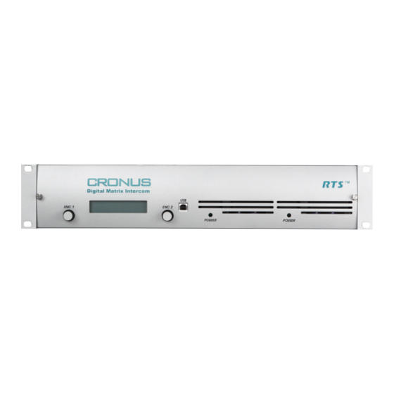
TABLE 1. Controls, Connections, and Cronus backcard. There are two Cronus backcards, an MDR backcard and an RJ-12 backcard. You can have up to four backcards installed on Cronus. You can have ny combination of backcards on the Cronus, too... - Page 9 Front and Rear Panel Controls and Connections There are two USBUSB connections on the Cronus; one on the front panel and one on the back panel (J7). Cronus system can use the USB port connect with a PC. This allows for the most USB Connection flexibility when planning where to use the system.
-
Page 10: Cronus Gain Structure
Introduction Cronus Gain Structure Cronus Gain Structure. The table below shows the gain level adjustments for Cronus ADAM, TABLE 2. and Zeus. MAX Audio Input Gain Control Input Level Range via AZedit Cronus +10dBu -20dB to +20dB V0.2.x V1.0.0 +20dB... -
Page 11: Specifications
Introduction Specifications Analog Inputs and Outputs Signal Type ...balanced Nominal Level ... 8dBu Maximum Level... 20dBu Input Impedance ... 22k Ohm Output Impedance...600 Ohm SNR at 20 dBu: A/D and D/A Sampling Rate... 48 kHz Resolution ... 24 bits Performance SNR at 20 dBu: (A-weighted) ... - Page 12 ... 75 Ohm coax connector 100 Base Tx (Cat5) Fiber Optic Type ...HFCT-5208M The fiber cable recommended for Cronus Single mode SM SC-SC Duplex type. Two SC-SC simplex pair will work, but you will have to verify which end to connect to each other.
- Page 13 Introduction MDR Connector Pin Number Port Function Data + Data - Audio To Matrix + Audio To Matrix - Audio From Matrix + Audio From Matrix - Data + Data - Audio To Matrix + Audio To Matrix - Audio From Matrix + Audio From Matrix - Data + Data -...
-
Page 14: Determining The Master System From The Slave Systems
Determining the Master System From the Slave Systems By default, Cronus is set to operate in “stand alone” mode. You will need a license file to link Cronus frames together. In order to link 2 or more Cronus systems together, each must have the optional linking firmware installed. To purchase the firmware, contact RTS sales. -
Page 15: Cronus System Diagram And Frame Cabling
(see cabling diagram at right). Each frame can support up to 32 ports, and each system can have a maximum of 128 ports (all four frames available). By adding a connection to a Cronus Bus Expander (CBX) on ADAM, Cronus can be linked to other Cronus Systems, increasing the number of available ports able to communicate with one another. - Page 16 Introduction Cable drawings for PAP32, AZedit, Trunking and UIO-256/LCP-102. TABLE 7.
-
Page 17: Cronus Menu Structure
Set Frame ID In a single frame Cronus system, the frame will always be Stand Alone (or the Master frame). In a multi-frame system, the first time Cronus is powered on, each frame will show as Frame 1 and will need to be configured, either manually or by autoconfig, to designate which frame it is. - Page 18 Use the ENC1 knob to adjust the IN Gain. Use the ENC2 knob to adjust the OUT Gain. NOTE: You can change the gain levels in AZedit and see the results on Cronus almost immediately. For more information on gain levels, see Figure 2 on page 4.
-
Page 19: Status Menu
Cronus Menu System Introduction Double-tap the ENC1 knob to exit the threshold set menu item. Port displays. Turn the ENC1 knob to Hold Time. Tap the ENC1 knob. Hold Time appears. Turn the ENC1 knob to set the hold time (up to 12.5 seconds). -
Page 20: Status, Crosspoints
TABLE 8. Status, Frames Frames displays the status of each of the Cronus frames. It tells if the frame is still active or if it has been deactivated. Turn the ENC1 knob to scroll to Status. When Status is displayed, tap the ENC1 knob. -
Page 21: Status, Gpi Output
You should check the status of the Frame Clock and the Link to each frame. This is good for diagnostic troubleshooting. NOTE: Frame 1 (Master) will only show the Frame 2 status because it only connects to one other Cronus frame. -
Page 22: Cronus Menu System Quick Reference
Cronus Menu System Quick Reference Menu Access TABLE 9. On the front panel of the Cronus system, tap the ENC1 encoder knob. The word Status appears. Turn the ENC2 encoder knob clockwise to scroll forward or counter-clockwise to scroll backwards through the list of menus. -
Page 23: Cronus And Azedit
Cronus or AIO-16 at a preset threshold level, the audio lines are open for conversation between ports. With Cronus, you can set the Vox threshold from the front panel or you can set it through AZedit. In AZedit there are two ways to access the Vox Settings screen. -
Page 24: Accessing Vox
Cronus and AZedit Accessing Vox To access the Vox Settings screen from the System menu, do the following: From the System menu in AZedit, select Vox. The Vox Settings Screen appears. NOTE: You can change the threshold levels and hold times of more than one port at a time by pressing the CTRL key and... - Page 25 Vox Settings in AZedit Screen Item Field Type Threshold Adjust arrow keys Threshold Level display box Threshold adjust slider Set To button Description Use the arrow keys to increase or decrease the vox threshold by.5 dB (-127 dB Down to 0.0 dB). You can see the level adjustments in the parameter display window (to the right). : You can select multiple ports to change at the same time.
- Page 26 Real-Time Changes time dynamically on the connected device (Cronus or AIO-16). : When making adjustments from the front panel of the Cronus take into consideration NOTE that AZedit has a 5 second display refresh rate which will cause a delay in what is seen in the application.
- Page 27 Vox Settings in AZedit Disable Vox button Reset Threshold button Reset Hold Time button Select All button De-select All button Invert Selection button The Disable Vox buttons disables Vox on the selected port (s). Select a port or multiple ports where Vox is enabled. Click Disable Vox.
- Page 28 Cronus and AZedit...
-
Page 29: Ethernet Setup For Cronus
NOTE: The PC must be running version 2.06.07 or later of AZedit and have an Ethernet card installed. Verify Cronus is connected to the PC using either a USB (universal) or RS-232 (ADAM standard) cable. The USB drivers can be found in the AZedit software directory (C:\Telex\AZedit|V20701|USB). You may only use on USB connection (front panel or back panel) at a time. -
Page 30: Download Firmware For Cronus
In the IP Address field, either enter the Cronus IP Address you wish to connect with, or click the Search button. The search button scans the network for any Cronus devices. If multiple units are on the network, each will appear in the list. - Page 31 Connecting Cronus to the PC and the Network From the Status menu, select Software Versions, then Master Controllers. The Master Controller Version Information screen appears. Highlight the Cronus version to be updated. You may select more than one version at a time by holding the CTRL key down while you select.
-
Page 32: Finding The Mac Address For Cronus
The Ethernet Setup screen appears. The MAC Address aappears at the bottom of the screen. NOTE: If you have multiple Cronus systems linked together, you will need to individually connect them to the PC to see the MAC address. You cannot look at multiple Cronus MAC Addresses at the same time. -
Page 33: Final Assembly Drawing
Final Assembly Drawing Cronus Final Assembly - see Table 10, “Final Assembly,” on page 28 for descriptions to the corresponding numbers. - Page 34 Figure 10. Item AI/o Rear PC Board Assembly, MDR SCSI Part No. 9070-7770-000 Coax Link Module Card Plate 9150-7770-000 Cronus Fiber Link Module PCB 9020-7770-000 Fiber Link Module Card Plate 51847-022 Fiber Link Module Cable Assy 9030-7784-000 591601-001 9110-7770-000 9110-7786-000...
-
Page 36: Wiring Diagram
Wiring Diagram... -
Page 37: Basic Network Configuration
Basic Network Configuration Appendix A Basic Network Configuration Basic Network Configuration This section covers basic network configuration set-up and testing. Also covered are basic concepts and operations, including the difference between LAN and WAN networks and how IP Addressing is used. In a networked environment, such as a company, typically there are many computers connected together using a router or a switch. -
Page 38: Wide Area Network
A wide area network (WAN) connects two or more LANs and can span a relatively large geographical area. For example, Telex Headquarters in Burnsville, MN is connected to several branch offices in Nebraska and Arkansas over a WAN. The WAN in existence is the Internet. -
Page 39: Accessing The Wide Area Network (Wan)
80 is used for HTTP traffic. When you type an address into the address bar of a web browser, your computer goes to find an IP Address for the url you are requesting (http://www.telex.com). To obtain this address, the computer contacts a DNS server (Domain Name Server). - Page 40 Basic Network Configuration Packet Translation Table 2. Packet before Translation Source Port IP Address Number 10.2.100.1 1031 Internet From 192.156.136.22 Internet Amazingly, all the address translation that occurs takes place automatically in order to make web browsing and other functions easier.
-
Page 41: Ip Addresses
Basic Network Configuration IP ADDRESSES If you do not know your IP Address, you can open a DOS screen in a Windows screen. To find your IP Address using ipconfig, do the following: From the Start Menu, open a Command Prompt screen. At the prompt, type ipconfig, then press Enter. -
Page 42: Ping A Computer
Ping a Computer Pinging a computer on the network makes sure it is able to be “seen” and receive messages on the network. NOTE: You can also ping your RVON-8 card to verify that it is responding over the network by putting the cards IP Address in place of the computer IP Address. -
Page 43: Rvon Configuration
Ports necessary for RVON card functionality. Table 4. Port Port Description 2076 UDP Call Control Signalling 2077 UDP Audio Packets 2079 UDP Telex Proprietary Signalling 2080 TCP Telex Keypanel Protocol 2081 UDP Pass Through Serial 2082 TCP Firmware Download 2100 Remote Administration... - Page 44 Below is an example of a router configuration screen. Not all routers are configured the same way and may not look exactly like this screen. NOTE: Linksys™ supports up to 253 nodes on a router. This is why it is called a Router/Switch because there are WAN functions like a router as well as having a 4-port LAN switch.
-
Page 45: Network Terminology
A DNS Server is an Internet service that translates domain names (for example, in the URL http:// www.telex.com, the domain name is the telex.com) into IP Addresses. The Internet is based on IP Addresses which are numeric and since domain names are alphabetic, they are easier to remember. Every time a domain name is used it must go through the DNS server to be translated into an IP Address. - Page 46 A wide area network connects two or more LANs and can span a relatively large geographical area. For example, Telex Headquarters in Burnsville, MN is connected to several of its branch offices in Nebraska and Arkansas over the wide area network. The largest WAN is the Internet.
-
Page 47: Breakout Panels
Breakout Panels provide a convenient way of expanding the port capacity of a Cronus Intercom System. Currently, there are three breakout panels for use with the Cronus MDR backcard: XCP-32-DB9, XCP-48-RJ45, and XCP-48-Telco. On the Cronus you can have up to four MDR backcards mounted on the chassis to give you that many more keypanel ports. Pin Number... -
Page 48: Xcp-32-Db9 Breakout Panel
The XCP-48-DB9 breakout panel is the newly created 32- port DB9 breakout panel with MDR connecotr for the AIO- 16. It allows you to expand the number of DB-9 serial ports on the Cronus. NOTE: When using the 32-port DB-9 breakout panel, you must use the MDR backcard... - Page 49 Breakout Panels Pin Number PORT FUNCTION Audio from Matrix + Audio from Matrix - NOTE: There are 4 MDR connectors on the XCP-32-DB9 Breakout Panel. MDR Connector Port 9-16 17-24 25-32 Description Pin 1 Keypanel Data + Pin 2 Keypanel Data - Pin 3 Pin 4 Audio Out +...
-
Page 50: Xcp-48-Rj45 Breakout Panel
XCP-48-RJ45 Breakout Panel (part number 9000-7809-000) FIGURE 2. The XCP-48-RJ45 is the newly created 48-port RJ45 breakout panel with MDR connector for the Cronus. It allows you to expand the number of RJ-45 ports on the ADAM system, up to 48 ports. - Page 51 Breakout Panels Pin Number Port Function Audio from Matrix + Audio from Matrix - NOTE: There are 6 MDR Connector on the XCP-48 Telco Breakout MDR Connector port 9-16 17-24 25-32 33-40 41-48 Description Pin 1 Pin 2 Keypanel Data - Pin 3 Audio Out + Pin 4...
-
Page 52: Xcp-48-Telco Breakout Panel
XCP-48-Telco Breakout Panel (part number 9000-7822-000) FIGURE 3. The XCP-48-Telco is the newly created breakout panel with MDR connector for the Cronus. It combines audio to matrix, audio from matrix, and data pairs. It then routes them on individual Telco connectors. - Page 53 Breakout Panels Pin Number Port Function Audio to Matrix - Audio from Matrix + Audio from Matrix - There are 6 MDR Connectors on the XCP-48-TELCO Breakout Panel. MDR Connector port 9-16 17-24 25-32 33-40 41-48 Telco Backcard Telco Connector J1, J4 Pin Number Port Function Audio to Matrix +...