Table of Contents
Advertisement
Advertisement
Table of Contents

Related Manuals for RTS Cronus


Summary of Contents for RTS Cronus
- Page 1 Cronus Digital Intercom Matrix 9350-7770-000 Rev N 5/2007...
- Page 2 OTICE The product information and design disclosed herein were originated by and are the property of Telex Communications, Inc. Telex reserves all patent, proprietary design, manufacturing, reproduction, use and sales rights thereto, and to any article disclosed therein, except to the extent rights are expressly granted to others.
-
Page 3: Table Of Contents
Download Cronus License File ... 24 Ethernet Setup for Cronus ... 25 TABLE CONTENTS Connecting Cronus to the PC and the Network .25 Download Firmware for Cronus ...26 Finding the MAC Address for Cronus ...28 Final Assembly Drawing ...29 Wiring Diagram ...32 RVON-C RTS Voice Over Network for Cronus ...33... - Page 4 Access Serial Command Mode ...68 Serial Command Table ...69 Codec Specifications ...70 RVON-C Default Setup ...71 Install Front and Back Cards in Cronus ...73 Plug in Ethernet ...73 Launch AZedit and Connect to the Cronus Frame ...74 Configure the RVON-C Card ...75 Configure the Devices Connected to the RVON-C Card ...76...
-
Page 5: Introduction
128 port matrix. Through the use of standard video coaxial cable, the maximum distance between the first and last Cronus system can be 300 ft., and still appear as a single matrix. However, when using the Fiber Option card, the distance is increased up to 15 kilometers nominally. -
Page 6: Differences Between Cronus And Adam
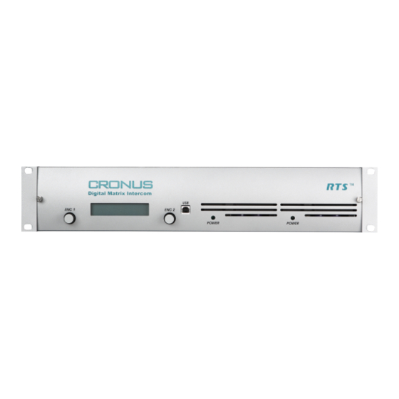
FIGURE 1. Controls, Connections, and Cronus backcard. There are two Cronus backcards, an MDR backcard and an RJ-12 backcard. You can have up to four backcards installed on Cronus. You can have ny combination of backcards on the Cronus, too (for example, you can have two RJ-12 backcards and two MDR backcards NOTE: For more information on a VOIP option card (RVON-C) for the Cronus, See “RVON-C RTS Voice Over Network for... - Page 7 Display Panel LCD display showing menu options. There are two USBUSB connections on the Cronus; one on the front panel and one on the back panel (J7). Cronus system can use the USB port connect with a PC. This allows for USB Connection the most flexibility when planning where to use the system.
-
Page 8: Cronus Gain Structure
Introduction Cronus Gain Structure Cronus Gain Structure. The table below shows the gain level adjustments for Cronus FIGURE 2. ADAM, and Zeus. Input Gain MAX Audio Control Range Input Level via AZedit Cronus +10dBu -20dB to +20dB V0.2.x V1.0.0 +20dB... -
Page 9: Specifications
Introduction Specifications Analog Inputs and Outputs Signal Type ...balanced Nominal Level ... 8dBu Maximum Level... 20dBu Input Impedance ... 22k Ohm Output Impedance...600 Ohm SNR at 20 dBu: A/D and D/A Sampling Rate... 48 kHz Resolution ... 24 bits Performance SNR at 20 dBu: (A-weighted) ... - Page 10 ... 75 Ohm coax connector Fiber Optic Type ...HFCT-5208M The fiber cable recommended for Cronus Single mode SM SC-SC Duplex type. Two SC-SC simplex pair will work, but you will have to verify which end to connect to each other.
- Page 11 Introduction MDR Connector Pin Number Port Data + Data - Audio To Matrix + Audio To Matrix - Audio From Matrix + Audio From Matrix - Data + Data - Audio To Matrix + Audio To Matrix - Audio From Matrix + Audio From Matrix - Data + Data -...
-
Page 12: Determining The Master System From The Slave Systems
Determining the Master System From the Slave Systems By default, Cronus is set to operate in “stand alone” mode. You will need a license file to link Cronus frames together. In order to link 2 or more Cronus systems together, each must have the optional linking firmware installed. To purchase the firmware, contact RTS sales. -
Page 13: Cronus System Diagram And Frame Cabling
POWER 1 POWER 2 The Cronus Intercom System has four frames, one Master and three Slave stations (see system diagram FIGURE 5. on left) connected via coaxial cables (see cabling diagram at right). Each frame can support up to 32 ports, and each system can have a maximum of 128 ports (all four frames available). - Page 14 Introduction PAP32 Cable Drawing DE9P (male) Cronus Trunking Cable Drawing Cronus, J3 Cable drawings for PAP32, AZedit, Trunking and UIO-256/LCP-102. FIGURE 7. DE9P (male) 9-pin DE9P (male) 2 RX Cronus 3 TX PAP-32 5 GND ICP-2000 (J1-J8) Cronus, J4 AZedit...
-
Page 15: Default Jumper Settings For The Master Controller Board
Write Protect Flash Chips IC9 and IC10 (Code Flash) Write Protect Flash Chips IC11 and IC12 (Config Flash) NOTE: If you have board 9030-7785-000, see “Cronus Master Controller Card 9030-7785-000” on page 87 for the Default Jumper settings. DESCRIPTION Populate jumper across pins 2 and... -
Page 16: Default Jumper Settings For The Cronus Aio Board
Introduction Default Jumper Settings for the Cronus AIO Board Cronus AIO Board 9030-7784-000 FIGURE 9. Jumper 5 volt Power Isolation DSP Debug Port Description Populate Jumper across J1 Populate Jumpers across J2: Pins 5-6 Pins 7-8 Pins 9-10 Pins 11-12... -
Page 17: Cronus Menu Structure
Set Frame ID In a single frame Cronus system, the frame will always be Stand Alone (or the Master frame). In a multi-frame system, the first time Cronus is powered on, each frame will show as Frame 1 and will need to be configured, either manually or by autoconfig, to designate which frame it is. - Page 18 Use the ENC1 knob to adjust the IN Gain. Use the ENC2 knob to adjust the OUT Gain. NOTE: You can change the gain levels in AZedit and see the results on Cronus almost immediately. For more information on gain levels, see Figure 2 on page 4.
-
Page 19: Status Menu
Cronus Menu System Introduction Double-tap the ENC1 knob to exit the threshold set menu item. Port displays. Turn the ENC1 knob to Hold Time. Tap the ENC1 knob. Hold Time appears. Turn the ENC1 knob to set the hold time (up to 12.5 seconds). -
Page 20: Status, Crosspoints
TABLE 1. Status, Frames Frames displays the status of each of the Cronus frames. It tells if the frame is still active or if it has been deactivated. Turn the ENC1 knob to scroll to Status. When Status is displayed, tap the ENC1 knob. -
Page 21: Status, Gpi Output
You should check the status of the Frame Clock and the Link to each frame. This is good for diagnostic troubleshooting. NOTE: Frame 1 (Master) will only show the Frame 2 status because it only connects to one other Cronus frame. -
Page 22: Cronus Menu System Quick Reference
Menu List - Tree Diagram TABLE 2. On the front panel of the Cronus system, tap the ENC1 encoder knob. The word Status appears. Turn the ENC2 encoder knob clockwise to scroll forward or counter-clockwise to scroll backwards through the list of menus. -
Page 23: Cronus And Azedit
Cronus or AIO-16 at a preset threshold level, the audio lines are open for conversation between ports. With Cronus, you can set the Vox threshold from the front panel or you can set it through AZedit. In AZedit there are two ways to access the Vox Settings screen. -
Page 24: Accessing Vox
Cronus and AZedit Accessing Vox To access the Vox Settings screen from the System menu, do the following: From the System menu in AZedit, select Vox. The Vox Settings Screen appears. NOTE: You can change the threshold levels and hold times of more than one port at a time by pressing the CTRL key and... - Page 25 Vox Settings in AZedit Screen Item Field Type Threshold Adjust arrow keys Threshold Level display box Description Use the arrow keys to increase or decrease the vox threshold Down by.5 dB (-127 dB to 0.0 dB). You can see the level adjustments in the parameter display window (to the right).
- Page 26 Real-Time Changes Vox and hold time dynamically on the connected device (Cronus or AIO- 16). : When making adjustments from the front panel of the Cronus take...
- Page 27 Supported? that supports Vox (either a Cronus or AIO-16 card). : Cronus and AIO-16 are the only devices, presently, that support NOTE Vox. When a green is displayed, the device supports Vox. When a red displayed, the device does not support Vox.
-
Page 28: Download Cronus License File
To link more than one Cronus system together, you must have linking software installed on the system (normally, this is loaded at time of purchase). If you are adding a Cronus Intercom System to an existing Cronus matrix, you may need to load a license file on your existing system. -
Page 29: Ethernet Setup For Cronus
NOTE: The PC must be running version 2.06.07 or later of AZedit and have an Ethernet card installed. Verify Cronus is connected to the PC using either a USB (universal) or RS-232 (ADAM standard) cable. The USB drivers can be found in the AZedit software directory (C:\Telex\AZedit|V20701|USB). You may only use on USB connection (front panel or back panel) at a time. -
Page 30: Download Firmware For Cronus
In the IP Address field, either enter the Cronus IP Address you wish to connect with, or click the Search button. The search button scans the network for any Cronus devices. If multiple units are on the network, each will appear in the list. - Page 31 Connecting Cronus to the PC and the Network From the Status menu, select Software Versions, then Master Controllers. The Master Controller Version Information screen appears. Highlight the Cronus version to be updated. You may select more than one version at a time by holding the CTRL key down while you select.
-
Page 32: Finding The Mac Address For Cronus
The Ethernet Setup screen appears. The MAC Address aappears at the bottom of the screen. NOTE: If you have multiple Cronus systems linked together, you will need to individually connect them to the PC to see the MAC address. You cannot look at multiple Cronus MAC Addresses at the same time. -
Page 33: Final Assembly Drawing
Final Assembly Drawing Cronus Final Assembly - see Table 3, “Final Assembly,” on page 30 for descriptions to the corresponding numbers. - Page 34 Figure 3. Item AI/o Rear PC Board Assembly, Part No. MDR SCSI 9070-7770-000 Coax Link Module Card Plate 9150-7770-000 Cronus Fiber Link Module PCB 9020-7770-000 Fiber Link Module Card Plate 51847-022 Fiber Link Module Cable Assy 9030-7784-000 591601-001 9110-7770-000 9110-7786-000...
-
Page 36: Wiring Diagram
Wiring Diagram... -
Page 37: Rvon-C
RVON-C RTS Voice Over Network for Cronus Description of the RVON-C Voice Over Network Card Installed directly into the Cronus Intercom frame, the RVON-C provides voice over IP (Internet Protocol) communications for ® the RTS Cronus intercom system. In general, voice over IP means sending voice information in digital form using discrete packets rather than the traditional telephone network. -
Page 38: Features
Features Installation The RVON-C card is hot-swappable and installs in any available slot in a Cronus Intercom System. It provides a single RJ-45 Ethernet connection for use with a 10 BASE-T or 100 BASE- TX network. It also has a DB-9 connection for an RS-232 or RS-485 pass-thru port. - Page 39 Specifications DB-9 Serial Port via backcard Power... 5W Typical Physical ...8.25”W x 6.25”L RVON-C JUMPERS and CONNECTIONS A selectable RS-232/485 serial port is at connector J1 Serial (See Figure 11 on page 37) on the back card. Jumper connections on J10, J11, and J12 (on the front card, see Figure 10 on page 36.) select the signal mode on J1. •...
- Page 40 RVON-C RTS Voice Over Network for Cronus C202 C179 C188 C187 R148 R164 R160 R161 R165 R162 R156 R152 C151 J10, J11, C150 R150 and J12 Pin 1 R181 R182 XOSC1 Frontcard - RVON-C 9030-7835-000 FIGURE 10. U121A C104 C156...
- Page 41 Specifications J202 J1 Serial MTG230_600 RVON-C Backcard FIGURE 11. RVON-C RVON-C Backplate FIGURE 12. J201 LINK SERIAL ETHERNET 2005 TELEX J2 Serial J203 MTG230_600...
-
Page 42: Installation Of The Rvon-C Card Into The Cronus System
• When inserting the RVON-C card into the Cronus system, make sure to insert it into a compatible backcard. If the card is inserted into a incompatible backcard, undesirable results can occur. -
Page 43: Switches And Connections
RVON-C card in case the native flash program becomes corrupt. DIP Switch 8 DEBUG ONLY! Warning: DIP Switch 8 should always be left in the OFF position. It is reserved for debugging and can have intended consequences. CLOSED OPEN RVON-C DIP Switch panel FIGURE 13. User: telex Password: password... -
Page 44: Configuring The Rvon-C Card With Azedit
RVON-C RTS Voice Over Network for Cronus Configuring the RVON-C Card with AZedit Once the RVON-C card is inserted into the Intercom, AZedit will automatically recognize the card. NOTE: Requires intercom firmware and AZedit software that support RVON cards. To Configure the RVON-C card, do the following: From the Status menu, select I/O cards. - Page 45 From the Packet Size drop down list, select the size of each audio packet. NOTE: A CODEC is an algorithm used to compress audio. There are 5 Codices support by Telex: G.711μs law, G.711A law, G.729AB, G.723 (5.3k) and G.723 (6.3k). The type of CODEC will dictate the quality of audio you hear and the network...
-
Page 46: Rvon-C Connection Status Screen
RVON-C RTS Voice Over Network for Cronus bandwidth used. The packet size determines how much audio data is carried across the network in each transmitted packet. The CODEC type and pack size chosen require different amounts of bandwidth from the network ( See “Specifications” on page 34). - Page 47 RVON-C Connection Status Screen Right-click the card with which you want to work. A context menu appears. Select RVON Connection Status. The RVON Connection Status screen appears. The Connection Status screen contains six pages of information about the selected channel and are described in detail on the following pages. Screen Item Select Local Card and Channel RVON Card...
- Page 48 RVON-C RTS Voice Over Network for Cronus Screen Item Attempts / Drops Current Call State Origination / Termination Release Reason Connection Duration Compression Algorithm Audio Packet Size Voice Activity Detect (VAD) Description The number of times a call attempt has been made and dropped.
- Page 49 RVON-C Connection Status Screen Screen Item Description Playout Buffer Size Displays how much audio can be received from the network before packets are lost. This is four times bigger than configured packet size. This is a static system setting. Nominal Playout Displays how much audio is collected before playout begins.
- Page 50 RVON-C RTS Voice Over Network for Cronus Screen Item Description Voice Playout Displays the number of voice packets transmitted and received from the other side Packets (Tx/Rx) of the connection. DTMF Relay Displays the number of DTMF (dual tone multiple frequency) relay packets Packets (Tx/Rx) transmitted and received.
- Page 51 RVON-C Connection Status Screen Screen Item Invalid Headers Invalid MAC Address Invalid SSRC Invalid Payload DSP to Micro Overrun Invalid Destination Lost Packets Description Error Counts Displays how many IP packets could not be parsed. Displays how many invalid MAC addresses tried to connect. Displays the number of packets with an invalid SSRC.
- Page 52 RVON-C RTS Voice Over Network for Cronus Screen Items Description SERIAL TO The Serial to Ethernet information shows the serial data that is received on the serial connection ETHERNET and transferred to the Ethernet address of the card to which the serial data is sent.
-
Page 53: View Rvon-C Status From Cronus Front Panel
If you have more than one Cronus linked together, the slots will continue numbering slot 5, slot 6, and so on. Turn the selector knob to select the desired slot. -
Page 54: Download Rvon-C Firmware Through Azedit
RVON-C RTS Voice Over Network for Cronus RVON-C Status Descriptions TABLE 4. ACTION When Ethernet is selected: When Serial is selected: When VoIP Channel is selected: Download RVON-C Firmware through AZedit NOTE: AZedit sends the program directly to the RVON-C card over Ethernet. This is different from other I/O cards that receive the firmware from the Master Controller. - Page 55 Download RVON-C Firmware through AZedit Highlight the Version to be updated. You may select more than one version at a time by holding the CTRL key down while you select. Right-click the highlighted selections and select Download Firmware. The Firmware Download window appears. Using the browse feature, browse to the file to be downloaded.
- Page 56 RVON-C RTS Voice Over Network for Cronus Click Begin Download. The download begins. Click OK. The RVON-C firmware download is complete. This may take a minute or two to occur. Verify the version upgrade in the I/O Card Version Information Window is correct.
- Page 57 Download RVON-C Firmware through AZedit FIGURE 14. AIO-BC-MC # 2 AIO-BC-MC # 2 AIO-BC-MC # 1 AIO-BC-MC # 1 RVON-C System Diagram BLANK...
- Page 58 RVON-C RTS Voice Over Network for Cronus...
-
Page 59: Basic Network Configuration
Basic Network Configuration Appendix A Basic Network Configuration Basic Network Configuration This section covers basic network configuration set-up and testing. Also covered are basic concepts and operations, including the difference between LAN and WAN networks and how IP Addressing is used. In a networked environment, such as a company, typically there are many computers connected together using a router or a switch. -
Page 60: Wide Area Network
A wide area network (WAN) connects two or more LANs and can span a relatively large geographical area. For example, Telex Headquarters in Burnsville, MN is connected to several branch offices in Nebraska and Arkansas over a WAN. The WAN in existence is the Internet. -
Page 61: Accessing The Wide Area Network (Wan)
80 is used for HTTP traffic. When you type an address into the address bar of a web browser, your computer goes to find an IP Address for the url you are requesting (http://www.telex.com). To obtain this address, the computer contacts a DNS server (Domain Name Server). - Page 62 Packet Translation Table 2. Packet before Translation Source Port IP Address Number 10.2.100.1 1031 Internet From 192.156.136.22 Internet Amazingly, all the address translation that occurs takes place automatically in order to make web browsing and other functions easier. This is also a way for large web hosting services to speed up the network by having different devices perform different functions.
-
Page 63: Ip Addresses
Basic Network Configuration IP ADDRESSES If you do not know your IP Address, you can open a DOS screen in a Windows screen. To find your IP Address using ipconfig, do the following: From the Start Menu, open a Command Prompt screen. At the prompt, type ipconfig, then press Enter. -
Page 64: Ping A Computer
Ping a Computer Pinging a computer on the network makes sure it is able to be “seen” and receive messages on the network. NOTE: You can also ping your RVON-8 card to verify that it is responding over the network by putting the cards IP Address in place of the computer IP Address. -
Page 65: Rvon Configuration
Ports necessary for RVON card functionality. Table 4. Port Port Description 2076 UDP Call Control Signalling 2077 UDP Audio Packets 2079 UDP Telex Proprietary Signalling 2080 TCP Telex Keypanel Protocol 2081 UDP Pass Through Serial 2082 TCP Firmware Download 2100 Remote Administration... - Page 66 Below is an example of a router configuration screen. Not all routers are configured the same way and may not look exactly like this screen. NOTE: Linksys™ supports up to 253 nodes on a router. This is why it is called a Router/Switch because there are WAN functions like a router as well as having a 4-port LAN switch.
-
Page 67: Network Terminology
A DNS Server is an Internet service that translates domain names (for example, in the URL http:// www.telex.com, the domain name is the telex.com) into IP Addresses. The Internet is based on IP Addresses which are numeric and since domain names are alphabetic, they are easier to remember. Every time a domain name is used it must go through the DNS server to be translated into an IP Address. - Page 68 A wide area network connects two or more LANs and can span a relatively large geographical area. For example, Telex Headquarters in Burnsville, MN is connected to several of its branch offices in Nebraska and Arkansas over the wide area network. The largest WAN is the Internet.
-
Page 69: Rvon Serial And Telnet Commands
RVON Serial and Telnet Commands RVON-C card programming can be done via direct serial or telnet connection. There are several physical connections to an RVON-C card. • Direct serial through custom debug cable (J7 6-pin bottom front) The customer debug cable always functions as the general -purpose debug tool. •... -
Page 70: Rvon-C Boot Download
RVON-C Boot Download ***************************** RVON-C Revision 1.00.02 (C) Copyright 2003 Telex Inc. All Rights Reserved. Flash File System initialized. DIP Switch settings:...XXXX Configuration via AZedit disabled (via DIP Switch 1 on) Back card UART enabled for pass-through serial (via DIP Switch 6 off) - Page 71 RVON-C Boot Download Adding 5160 symbols for standalone. appCreate: autoBootLevel=2 MXP environment is created. Creating RVON application... -> Bringing DSP subsystem out of reset... DSP Daughtercard type is set to NONE - No DSP Daughtercard Found 0000004883 - ROOT: FPGA Version = ff00 0000004890 - ROOT: Channel 2 Remote IP Address is unconfigured 0000004892 - ROOT: Channel 3 Remote IP Address is unconfigured 0000004894 - ROOT: Channel 4 Remote IP Address is unconfigured...
-
Page 72: Access Serial Command Mode
Access Serial Command Mode There are many different serial port commands supported from here, but it is NOT recommended that any be used except: dbgcmd At a DOS prompt, type “dbgcmd”, then press Return. This places the serial port into the MXP> (MXP command mode) The MXP Command Mode is the only mode that will be used. -
Page 73: Serial Command Table
X.X.X.X Set the gateway IP Address for the RVON-8 card. Set the RVON user name for telnet access. abcdefg Default “telex” Set the RVON password for telnet access (8-40 characters). abcdefg Default “password” Set the VAD threshold (silence detection) Adaptive refers [adaptive ⎢#]... -
Page 74: Codec Specifications
Codec Specifications Codec Specifications Figure 6. 0,3,6,9 G.711 1,4,7,10 G.711 2,5,8,11 G.711 12,16 G.729 13,17 G.729 14,18 G.729 15,19 G.729 20,22 G.723 5.3k 24,26 G.723 6.3k 21,23 G.723 5.3k 25,27 G.723 6.3k NOTE : A channel consists of a transmitting and a receiving side, so the bandwidth is double for a bi-directional audio stream. NOTE : Bandwidth values are approximate maximums, actual bandwidth could be considerably lower with VAD enabled. -
Page 75: Rvon-C Default Setup
Pass-thru serial port IP Address for the RVON-C Card 9600 Set the pass-thru serial port baud rate for the RVON-C Card telex RVON-C user name for telnet access password RVON-C password for telnet access (8-40 characters) VAD Threshold DEFAULT... -
Page 77: Install Front And Back Cards In Cronus
• When inserting the RVON-C card into Cronus, be sure to insert it into a compatible back card. If the card is inserted into an incompatible back card, undesirable results can occur. -
Page 78: Launch Azedit And Connect To The Cronus Frame
Launch AZedit and Connect to the Cronus Frame NOTE: You can connect to Cronus using Serial, USB, or Network Connections. The following instructions show how to connect using a Network connection. For more information on configuring the network connection for the Cronus, see page 25. -
Page 79: Configure The Rvon-C Card
You will now see CRON in the lower right hand corner of the AZedit application. Configure the RVON-C Card Once you have a connection to Cronus, you are now ready to configure the RVON-C card within the Cronus system. To configure the RVON-C card, do the following: From the Navigation bar at the bottom of the AZedit application, click the RVON button. -
Page 80: Configure The Devices Connected To The Rvon-C Card
From the Packet Size drop down list, select the size of each audio packet. NOTE: A CODEC is an algorithm used to compress audio. There are 5 Codices supported by Telex: G.711μs law, G.711A law, G.729AB, G.723 (5.3k), G.723 (6.3k). The type of CODEC will dictate the quality of audio you hear and the network bandwidth used. -
Page 81: Setting Up A Serial Pass-Through Connection Or Serial Connection
NOTE: When making adjustments to the DIP switches and jumpers, you will need to take the front card out of the Cronus. To use the Serial Pass-Through, do the following: Set DIP Switch 6 to the OPEN position. -
Page 83: Breakout Panels
Breakout Panels provide a convenient way of expanding the port capacity of a Cronus Intercom System. Currently, there are three breakout panels for use with the Cronus MDR backcard: XCP-32-DB9, XCP-48-RJ45, and XCP-48-Telco. On the Cronus you can have up to four MDR backcards mounted on the chassis to give you that many more keypanel ports. Pin Number... -
Page 84: Xcp-32-Db9 Breakout Panel
The XCP-48-DB9 breakout panel is the newly created 32- port DB9 breakout panel with MDR connecotr for the AIO- 16. It allows you to expand the number of DB-9 serial ports on the Cronus. NOTE: When using the 32-port DB-9 breakout panel, you must use the MDR backcard... - Page 85 Pin Number PORT FUNCTION Audio from Matrix + Audio from Matrix - NOTE: There are 4 MDR connectors on the XCP-32-DB9 Breakout Panel. MDR Connector Port 9-16 17-24 25-32 Description Pin 1 Keypanel Data + Pin 2 Keypanel Data - Pin 3 Pin 4 Audio to Matrix +...
-
Page 86: Xcp-48-Rj45 Breakout Panel
XCP-48-RJ45 Breakout Panel (part number 9000-7809-000) FIGURE 16. The XCP-48-RJ45 is the newly created 48-port RJ45 breakout panel with MDR connector for the Cronus. It allows you to expand the number of RJ-45 ports on the ADAM system, up to 48 ports. - Page 87 Pin Number Port Function Audio from Matrix + Audio from Matrix - NOTE: There are 6 MDR Connector on the XCP-48 Telco Breakout MDR Connector port 9-16 17-24 25-32 33-40 41-48 Description Pin 1 Pin 2 Keypanel Data - Pin 3 Audio Out + Pin 4 Audio In +...
-
Page 88: Xcp-48-Telco Breakout Panel
XCP-48-Telco Breakout Panel (part number 9000-7822-000) FIGURE 17. The XCP-48-Telco is the newly created breakout panel with MDR connector for the Cronus. It combines audio to matrix, audio from matrix, and data pairs. It then routes them on individual Telco connectors. -
Page 89: Telco Backcard
Pin Number Port Function Audio to Matrix - Audio from Matrix + Audio from Matrix - There are 6 MDR Connectors on the XCP-48-TELCO Breakout Panel. MDR Connector port 9-16 17-24 25-32 33-40 41-48 Telco Backcard Telco Connector J1, J4 Pin Number Port Function Audio to Matrix +... -
Page 91: Legacy Master Controller Card Jumper Settings
Appendix E Cronus Master Controller Card 9030-7785-000 Legacy Master Controller Card Jumper Settings FIGURE 18. - Page 92 CONNECTOR DESCRIPTION J3 & 4 J Tag Connector and Flash Write Protect Cold Fire Test Mode +5 Volt Jumper 44k / 48k mode select J Tag Mode DRAM reset in debug mode J24 & J25 DSP Debug Ports DEFAULT SETTING Populate across pins 1 &...
- Page 93 Notes Notes...