Table of Contents
Advertisement
Quick Links
Sony Corporation
Printed in Japan
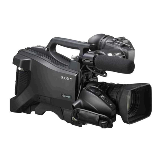
HD Color Camera
The supplied CD-ROM includes operating instructions for the HXC-D70 HD Color
Camera (Japanese, English, French, German, Italian, Spanish and Chinese ver-
sions) in PDF format. For more details, see "Using the CD-ROM Manual" on page
10.
Operating Instructions
Before operating the unit, please read this manual thoroughly
and retain it for future reference.
HXC-D70
© 2011 Sony Corporation
4-291-686-11 (2)
Advertisement
Table of Contents

Related Manuals for Sony HXC-D70


Summary of Contents for Sony HXC-D70
-
Page 1: Operating Instructions
4-291-686-11 (2) HD Color Camera The supplied CD-ROM includes operating instructions for the HXC-D70 HD Color Camera (Japanese, English, French, German, Italian, Spanish and Chinese ver- sions) in PDF format. For more details, see “Using the CD-ROM Manual” on page... - Page 2 Compliance with this directive implies conformity to the Record these numbers in the spaces provided below. Refer to following European standards: them whenever you call upon your Sony dealer regarding this • EN55103-1: Electromagnetic Interference(Emission) product. • EN55103-2: Electromagnetic Susceptibility(Immunity) This product is intended for use in the following Model No.
- Page 3 (commercial et industrie légère), E3 (urbain extérieur) et E4 (environnement EMC contrôlé, ex. studio de télévision). Pour les clients en Europe Le fabricant de ce produit est Sony Corporation, 1-7-1 Konan, Minato-ku, Tokyo, Japon. Le représentant autorisé pour EMC et la sécurité des produits est Sony Deutschland GmbH, Hedelfinger Strasse 61, 70327 Stuttgart, Allemagne.
-
Page 4: Table Of Contents
Connecting a Microphone to the AUDIO 2 IN Connector Table of Contents ................... 33 Attaching a UHF Portable Tuner (for a UHF Wireless Microphone System) ..........35 Mounting the Camera to a Tripod ......35 Using the Shoulder Strap (Optional)...... 36 Chapter 1 Overview Adjusting the Shoulder Pad Position .... - Page 5 Appendix Important Notes on Operation........ 76 Using a “Memory Stick Duo”........77 Exchanging the Battery of the Internal Clock ..78 Specifications ............79 Pin assignment ............81 Table of Contents...
-
Page 6: Chapter 1 Overview
Overview Chapter Product Configurations The HXC-D70 comprises the components as shown in the figure below. The operation of the basic camera unit is the same in all cases. HXC-D70K HXC-D70L Zoom Lens CBK-VF01 Microphone Viewfinder HXC-D70H Test Chart for Flange Focal... -
Page 7: Features
High picture quality and high performance demanding HD shooting. The HXC-D70 is an HD color video camera equipped with three-chip 2/3-type “Exmor” CMOS image sensors. The Position-adjustable shoulder pad approximately 2.07 million effective pixels image sensor The position of the shoulder pad can be adjusted for stable technology for full HD resolution (1920 ×... -
Page 8: System Configuration
3.5-type color LCD VF CBK-VF01 (supplied with HXC-D70K/ shown in the figures has been discontinued. For advice on HXC-D70L). choosing devices, please contact your Sony dealer or a Sony service representative. “Memory Stick Duo” operation The camera is equipped with a “Memory Stick Duo” slot, which... -
Page 9: System Operation Example (With The Hxcu-D70 Camera Control Unit)
System operation example (with the HXCU-D70 Camera Control Unit) DXF-20W/C50WA/51 Viewfinder Picture Monitor CBK-VF01 Microphone Viewfinder Return Video Input Intercom Headset HXC-D70 Sync Input Prompter Video Input Zoom Lens (for ENG/EFP) Video Output HD-SDI/ Multi-core Cable SD-SDI/VBS/HDMI “Memory Stick Duo”... -
Page 10: Using The Cd-Rom Manual
For information on pin assignment, see “DC OUT” in “Pin If you have lost or damaged the CD-ROM, you can purchase assignment” on page 81. a new one to replace it. Contact your Sony dealer or a Sony d Battery attachment shoe service representative. - Page 11 Note For your safety, and to ensure proper operation of the camera, Sony recommends the use of the following battery packs: BP- GL95A, BP-GL65A, BP-L60S, and BP-L80S. Locations and Functions of Parts and Controls...
-
Page 12: Accessory Attachments
Loosen this ring to adjust the left-to-right position of the viewfinder (see page 24). n Lens mount (special bayonet mount) Attach a lens. Consult your Sony dealer or a Sony service representative for information about available lenses. Locations and Functions of Parts and Controls... -
Page 13: Operating And Connectors Section
o Camera control unit (CCU) connector (multi-core Operating and Connectors Section interface) Set up a system with the HXCU-D70 or CCU-D50/D50P camera control unit using multi-core cables. Front p TRUNK connector (D-sub 9-pin) Use for trunk signal communication between the camera and HXCU-D70 Camera Control Unit. -
Page 14: Right Side
c WHT/BLK (automatic white/black balance adjustment) Right side switch Activate the automatic white/black balance adjustment functions. WHT: Adjust the white balance automatically. If the WHITE BAL switch (see page 15) is set to A or B, the white balance setting is stored in the corresponding memory. If the WHITE BAL switch is set to PRST, the automatic white balance adjustment function does not operate. - Page 15 d WHITE BAL (white balance memory select) switch Rear Control adjustment of the white balance. PRST: Adjust the color temperature to the preset value (the factory default setting: 3200K). Use this setting when you have no time to adjust the white balance. A or B: Recall the white balance adjustment settings already stored in A or B.
- Page 16 f INTERCOM control n DC IN (DC power supply input) connector (XLR 4-pin, • When a HXCU-D70 is connected, use this control to adjust female) the intercom volume level. The intercom volume level can Refer to “DC IN connector” in “Power Supply” on page 10. also be adjusted using the INTERCOM LEVEL control on o INTERCOM connector (XLR 5-pin) the front panel (see page 14).
-
Page 17: Auto Focus Lens (Supplied With Hxc-D70K)
c MACRO switch Auto Focus Lens (Supplied with HXC- When this switch is in the ON position, the macro mode is to ∞) D70K) enabled, allowing focusing over the whole range (5 cm including the macro range (from 5 cm to 90 cm from the front of the lens). -
Page 18: Viewfinder (Supplied With Hxc-D70K/D70L)
c Eyecup • If there are a number of objects within the screen at close and far range, the focus may not be on the intended subject. d Diopter adjustment ring In this case, with the subject on which you want to focus in Allows for optimal focus adjustment. -
Page 19: Viewfinder Screen Display
j AF (auto focus) indication Viewfinder Screen Displays the auto focus status. FULL: Full MF (full manual focus) mode Display MF *: Manual focus assist mode AF: Auto focus mode k 5600K mode indication Besides the video image, the viewfinder can display Displayed when the internal electrical filter (5600K) is set to characters and messages showing the camera settings and operation status, as well as items such as a center marker or... - Page 20 b ‘!’ indication area This area is used to display abnormal statuses, using the ‘!’ IND function. Display options can be set, using the menu. For details, see OPERATION > ‘!’ IND in the setup menu (page 57). CALL/TALLY indication in digital viewfinders Digital viewfinders have no tally lamps.
-
Page 21: Chapter 2 Preparations
Preparations Chapter 1 Release the buckle, 2 bundle the cable with the Connecting a Camera belt, 3 then lock the buckle again. Control Unit (CCU) When operating the camera in a system with a CCU, connect between the CCU connector of the camera and the CAMERA connector of the CCU, using a multi-core cable. -
Page 22: Standalone Operation
CCU, use a battery pack or AC power to operate it. Be sure to remove the rear cover before using a battery pack or AC power. For safety, use only a Sony battery pack or AC adaptor listed below. • BP-GL95A/GL65A/L60S/L80S Lithium-ion Battery Pack •... -
Page 23: Using A Battery Pack
Slide the battery pack down until its “LOCK” arrow points at the matching line on the camera. To an AC outlet Using a Battery Pack When a BP-GL95A/GL65A/L60S/L80S Battery Pack is used, the camera will operate for the time shown below. Model name Operating time 1 “LOCK”... -
Page 24: Attaching The Viewfinder
Remove the cover of the viewfinder connector and Attaching the Viewfinder couple it to the VF connector (rectangular). CAUTION When the viewfinder is attached, do not leave the camera with VF connector (rectangular) the eyepiece facing the sun. Direct sunlight can enter through the eyepiece, be focused in the viewfinder and cause fire. -
Page 25: Adjusting The Viewfinder Angle
To raise up the viewfinder barrel Adjusting the Viewfinder Angle 1 Push the clip on the bottom to release and 2 flip up the viewfinder barrel. You can adjust the angle of the viewfinder. It locks at the 120-degree position. To reverse the display (image/text indication) vertically The viewfinder can be rotated as much as 180 degrees toward... -
Page 26: Adjusting The Viewfinder Focus And Screen
To detach the viewfinder barrel Adjusting the Viewfinder Focus and Screen To adjust the viewfinder focus Turn the diopter adjustment ring until the viewfinder image is sharpest. Diopter adjustment ring To adjust the viewfinder screen Adjust the peaking, contrast, and brightness of the viewfinder screen with the controls shown below. -
Page 27: Attaching An Optional Viewfinder
Notes Attaching an Optional Viewfinder • Be sure to power off the camera before plugging the viewfinder connector into the VF connector on the camera. Attaching the DXF-20W viewfinder If the connector is plugged in while the power is on, the viewfinder may not operate correctly. - Page 28 Attach the provided viewfinder shoe to the camera. Couple the connector to the VF connector (20-pin, Align the holes in the rear of the viewfinder fitting shoe round) of the camera, and clip the connecting cable with the two pins on the VF shoe fixing bracket. Be sure into the cable clamp as shown in the following figure.
-
Page 29: Setting The Area Of Use
Detach the plate after loosening the screw (M2×5). Setting the Area of Use Attach the accessory shoe using either the four screws used for the camera (K3×8) or the four screws supplied with the shoe kit (K3×12). When using the camera for the first Slide the plate spring in the direction shown by the time arrow and secure the spring using the stopper. -
Page 30: Setting The Date/Time Of The Internal Clock
Turn the menu control knob to select the desired area Setting the Date/Time of of use. Setting Area of use the Internal Clock NTSC AREA NTSC (for areas other than Japan) NTSC(J) AREA NTSC (Japan) PAL AREA When using the camera for the first time, set the built-in clock a) The composite signal output from this camera is an NTSC to local time, using MAINTENANCE >... -
Page 31: Mounting And Adjusting The Lens
When the date/time setting is completed, set the Mounting and Adjusting DISPLAY/MENU switch to OFF to exit menu mode. the Lens First power off the camera, and then mount the lens using the following procedure. For information about using the lens, refer to the operation manual for the lens. -
Page 32: Adjusting The Flange Focal Length
When using a non-auto focus lens The lens supplied with the HXC-D70K is an aberration correction lens. Contact your Sony dealer or a Sony service Set the iris to manual. representative for information about other aberration correction lenses. -
Page 33: Preparing The Audio Input System
Plug the microphone cable into the AUDIO 1 IN Preparing the Audio Input connector. System Connecting a Microphone to the AUDIO 1 IN Connector Attach a microphone (supplied with HXC-D70K/D70L) to the microphone holder of the supplied viewfinder. Loosen the screw and open the microphone holder clamp. - Page 34 1 Remove the screw-hole cover on the top front of the 2 Tighten the screw. camera. 3 Position so that the microphone does not interfere with 2 Secure the CAC-12 to the camera, using the two the viewfinder and tighten the ball joint lock lever. supplied screws (+B4×8).
-
Page 35: Attaching A Uhf Portable Tuner (For A Uhf Wireless Microphone System)
Mounting the Camera to a UHF Wireless Microphone System) Tripod To use a Sony UHF wireless microphone system, power the camera off and then fit one of the following UHF portable tuners. Mount the camera to a tripod, using an optional VCT-U14 •... -
Page 36: Using The Shoulder Strap (Optional)
To remove the camera from the tripod adaptor Using the Shoulder Strap Hold down the red button and pull the lever in the direction of the arrow. (Optional) The optional shoulder strap (service part number: A-6772- 374-C) can be attached to the camera. To attach the shoulder strap Fit one of the clips to a shoulder strap fitting. -
Page 37: Adjusting The Shoulder Pad Position
To remove the shoulder strap Adjusting the Shoulder Press here and pull in the direction shown by the arrow to release. Pad Position You can slide the shoulder pad back and forth within a 40 mm range. This adjustment helps you get the best balance for shooting with the camera on your shoulder. -
Page 38: Chapter 3 Shooting
Shooting Chapter 5600K setting Basic Procedure for The 5600K ON/OFF function has been assigned to the COLOR TEMP. button at the factory. Shooting 5600K Example of lighting conditions Indoor shooting under lighting with lower color temperature, such as a halogen or tungsten lamp Note Outdoor shooting in daytime, or indoor... -
Page 39: Adjustments And Settings
Turn the menu control knob to change the setting, If any error message is displayed, retry the black balance and press the knob. adjustment. If the error message occurs again, consult your Sony dealer or Adjusting the Black Balance and the a Sony service representative. White Balance... -
Page 40: Setting The Electronic Shutter
Setting the Electronic Shutter If any error message is displayed, retry the white balance adjustment. If the error message occurs again, consult your Sony dealer or Note a Sony service representative. When a CCU or an external control device, such as an RCP/... -
Page 41: Changing The Reference Value For Automatic Iris Adjustment
Changing the Reference Value for System frequency Shutter speed (unit: seconds) 59.94i Automatic Iris Adjustment 1000 2000 59.94P The reference value for automatic iris adjustment can be 1000 2000 changed to aid the shooting of clear pictures of back-lit subjects, or to prevent blown-out highlights. The reference ECS (Extended Clear Scan) mode value for the lens iris can be set within the following range with Select this mode for obtaining images with no horizontal bands... -
Page 42: Using Servo Zoom
Using Servo Zoom White line indicating the current distance With the ZOOM switch set to SERVO, operate the power zoom lever. The current lens zoom position appears in the viewfinder, over the range 0 (wide-angle) to 99 (telephoto) (see page 19). Push to the W (wide) side when you want wide-angle, and push to the T (telephoto) side when you want telephoto. -
Page 43: Setting The Focus Assist Function
Setting the Focus Assist Function Level indicator (Its position and operations can be adjusted.) Using the OPERATION menu, the assist functions for easier focusing in the viewfinder can be activated. Adding a VF detail signal Adding a VF detail signal to sharp edges in the image in the viewfinder makes it easier to check the focusing condition by observing changes in the detail signal or in the color converted from the detail signal (color detail). -
Page 44: Setting The Camera Outputs
Set the DISPLAY/MENU switch to OFF to exit menu Menu page Item Setting mode. <DOWN CONVERTER> OUTPUT SIGNAL MAIN <TEST OUT> OUTPUT Notes Constantly outputting a return video • The level indicator and the effect area marker cannot be • When a CCU is connected, one of the signals being displayed simultaneously, whichever you set to ON later is supplied to the CCU can be output from the camera. -
Page 45: Using The Flash Band Compensation Function
When the camera is used in standalone status or When the flash band effects appears in two frames used with the CCU-D50/D50P Stitches together the split-field flash frames, regenerating a single frame in which a flash extends entirely. The input level from audio sources connected to the AUDIO 1 IN and AUDIO 2 IN connectors can be adjusted using the INTERCOM LEVEL control on the front panel. -
Page 46: Chapter 4 Menu And Detailed Settings
Menu and Detailed Settings Chapter VF MARKER MARKER Setup Menu Organization CENTER SAFETY ZONE and Levels EFFECT ASPECT MASK On this camera, settings are made in the setup menu, which SAFETY appears in the viewfinder. VF DETAIL VF DETAIL CRISP FREQUENCY Setup Menu Organization FAT MODE... - Page 47 PAINT menu RE.ROTATION SWITCH ASSIGN2 LENS VTR S/S SW STATUS FLARE FRONT RET2 GAMMA VR ASSIGN FRONT VR BLK GAM REAR VR KNEE HEAD SET INTERCOM MIC WHT CLIP LEVEL DETAIL POWER LVL DEP UNBAL SKIN DTL INTERCOM LEVEL SIDE TONE MATRIX PGM MIX LEVEL VIDEO LEVEL...
- Page 48 MAINTENANCE menu DETAIL 2 H/V RATIO FREQ AUTO SETUP AUTO BLACK MIX RATIO AUTO WHITE KNEE APT AUTO LEVEL AUTO WHITE SHADING SKIN DETAIL SKIN DTL AUTO BLACK SHADING SKIN GATE TEST AUTO HUE WHITE SHADING V SAW PHASE V PARA WIDTH H SAW H PARA...
- Page 49 FILE menu TEST OUT OUTPUT VBS-OUT READ (MS t CAM) OPERATOR FILE CHARACTER WRITE (CAM t MS) SYNC-OUT PRESET V-PHASE STORE PRESET FILE H PHASE FILE ID SDI OUT OUTPUT CAM MODE CHARACTER DATE CCZ OUT OUTPUT SCENE FILE POWER SAVE SDI OUT DOWN CONVERTER D.EXTENDER...
-
Page 50: Basic Menu Operations
DIAGNOSIS menu Basic Menu Operations BOARD STATUS The menus displayed in the viewfinder enable various settings of the camera. The following controls are used to operate the menus. PLD VERSION To enter menu mode, you can use the DISPLAY/MENU switch DPR1 either on the right side or the rear panel of the unit. -
Page 51: Displaying Menu Pages
Rear operation panel Menu Purpose PAINT This menu contains items for making detailed image adjustments while using a waveform monitor to monitor the waveforms output from the camera. Support of a video engineer is usually required to use this menu. Although you can also use an external control device to set the items on this menu, the menu Menu control... - Page 52 To change the displayed page To specify a character string When you press the menu control knob with the pointer Check that the pointer is located at the left of the page pointing to an item for which a character string, such as a file number then push on the menu control knob.
-
Page 53: Editing The User Menu
To add items to a page Editing the USER Menu Select USER MENU CUSTOMIZE on the TOP MENU You can select desired pages and items from the screen (page 51). OPERATION, PAINT, MAINTENANCE, FILE, and If this is the first time the USER MENU CUSTOMIZE DIAGNOSIS menus and register them to the USER menu. - Page 54 Add the items. Note 1 Turn the menu control knob until the page that has the You cannot insert a blank line on a page where 10 items have desired items appears, then push on the menu control already been registered. knob.
- Page 55 To delete a page On the EDIT PAGE screen of the USER MENU CUSTOMIZE menu, move the pointer to the page to be deleted and push on the menu control knob. The EDIT FUNCTION screen appears. Select DELETE then push on the menu control knob. The previously displayed page appears again, and the message “DELETE OK? YESbNO”...
-
Page 56: Menu List
Menu List Note These remarks are common for all the following menu tables. ON, OFF, 0, ... , in the Settings columns: Default settings Page No. nn (Unn): For the pages that have been registered on the USER menu at the factory, the USER menu page numbers are indicated in parenthesis. - Page 57 OPERATION Page title Item Settings Description Page No. <'!' IND> [IND] ON, OFF [IND]: Activates/deactivates the '!' indication 03 (U05) (page 19). [NORMAL] 1, 2, 3, 4 [NORMAL]: Specifies the conditions under (combination allowed) which the '!' indication is not to be displayed [IND] ON, OFF even if [IND] is ON.
- Page 58 OPERATION Page title Item Settings Description Page No. <VF DETAIL> VF DETAIL ON, OFF Adds detail signals to the edges of the subject. 05 (U02) 0 to 100% 25% CRISP -99 to 99 0 Removes faint detail signals Note FREQUENCY 9M, 14M, 18M Changes the detection range for the edge.
- Page 59 OPERATION Page title Item Settings Description Page No. <SWITCH ASSIGN1> GAIN [L]: -3, 0, 3, 6, 9, 12, 18, 24, 30, Sets the gain value when the GAIN selector is 10 (U09) 36, 42dB set to L. [M]: -3, 0, 3, 6, 9, 12, 18, 24, 30, Sets the gain value when the GAIN selector is 36, 42dB set to M.
- Page 60 OPERATION Page title Item Settings Description Page No. <EARPHONE> EARPHONE RECEIVE SEPARATE, MIX Sets the earphone output format. SELECT SEPARATE: Outputs different audio signals from the left and right channels. MIX: Outputs an audio signal from the left and right channels. INTERCOM - - -, LEFT, RIGHT, BOTH Sets the intercom audio output channel.
-
Page 61: Paint Menu
PAINT Menu PAINT Page title Item Settings Description Page No. <SW STATUS> FLARE ON, OFF Sets the flare compensation function to on or off. GAMMA ON, OFF Sets the gamma compensation function to on or off. BLK GAM ON, OFF Sets the black gamma compensation function to on or off. - Page 62 PAINT Page title Item Settings Description Page No. <GAMMA> LEVEL R/G/B/M: -99 to 99 0 Sets the gamma level. COARSE 0.35 to 0.45 to 0.90 Sets the gamma compensation value in steps of 0.05. (0.05 steps) TABLE STANDARD, HYPER Selects either the standard gamma or hypergamma.
- Page 63 PAINT Page title Item Settings Description Page No. <DETAIL 1> DETAIL ON, OFF Sets the detail adjustment (contour correction) function to on or off. LEVEL -99 to 99 0 Sets the detail level. LIMITER [M] -99 to 99 0 Sets the master level for the detail limiter. [WHT] -99 to 99 0 Sets the white detail limiter.
- Page 64 PAINT Page title Item Settings Description Page No. <MULTI MATRIX> PHASE 0, 23, 45, 68, 90, 113, 135, 158, Selects an axis (angle) for which the multimatrix 180, 203, 225, 248, 270, 293, adjustment to be made. 315, 338 -99 to 99 0 Independently sets the hue compensation for 16 axes.
-
Page 65: Maintenance Menu
PAINT Page title Item Settings Description Page No. <SCENE FILE> File number and file ID Stores and reads scene files (paint data). See FILE menu F02. STORE Stores scene files in the camera’s internal memory. STANDARD Execute by ENTER. READ (MStCAM) Reads a scene file from a “Memory Stick Duo.”... - Page 66 MAINTENANCE Page title Item Settings Description Page No. <BLACK SHADING> V SAW R/G/B: -99 to 99 0 Sets the SAW black shading compensation value in the vertical direction. V PARA R/G/B: -99 to 99 0 Sets the parabola black shading compensation value in the vertical direction.
- Page 67 MAINTENANCE Page title Item Settings Description Page No. <CIS COMP> FLICKER REDUCE Settings related to the flicker compensation function. MODE AUTO, ON, OFF Enables or disables flicker reduction. AUTO: Enabled when flicker is detected. ON: Always enabled. OFF: Disabled FREQ 60 Hz, 50 Hz Set to the frequency of the lighting fixture that is causing the flicker.
- Page 68 MAINTENANCE Page title Item Settings Description Page No. <OUTPUT FORMAT> CURRENT Displays the current format. M08 (U15) ACTIVE LINE [1080] 59.94i, 50i Set this item when turning the unit on for the [720] 59.94P, 50P first time. Selectable formats vary depending on Not displayed when a CCU is (When you change the ACTIVE the area of use.
- Page 69 MAINTENANCE Page title Item Settings Description Page No. <CCZ OUT> OUTPUT YCrCb, YC, RGB, - - - Sets the signal to be output from the CCZ-A connector when the camera is used on its own. Settings in ( ): When CCU-D50/D50P is connected - - -: When a CCU other than CCU-D50/D50P is connected...
- Page 70 MAINTENANCE Page title Item Settings Description Page No. <OTHERS 1> CAM BARS ON, OFF Displays or hides the color bar signal. V DTL CREATION NAM, G, R+G, Y Selects the source signal of V DTL. DTL H/V MODE H/V, V Only Selects the operating mode of the H/V RATIO function in DETAIL 2.
-
Page 71: File Menu
FILE Menu Five types of files can be used for easy adjustments of the camera; Operator, Reference, Scene, OHB, and Lens. You can store the items set with the OPERATION menu and customized USER menu in the Operator file. For the specific items included in these files, refer to the Maintenance Manual. FILE Page title Item... - Page 72 FILE Page title Item Settings Description Page No. <REFERENCE> STORE FILE Stores the current settings in the reference file to the camera’s internal memory. (Execute by ENTER.) STANDARD Reads the standard values in the reference file from the internal memory. (Execute by ENTER.) ALL PRESET Returns the camera settings to the factory...
-
Page 73: Diagnosis Menu
FILE Page title Item Settings Description Page No. <FILE CLEAR> PRESET OPERATOR Returns the operator file to the factory preset. (Execute by ENTER.) REFERENCE (ALL) Returns the reference file to the factory preset. (Execute by ENTER.) 10 SEC CLEAR ON, OFF Clears a specific item in the reference file by holding the menu control knob pressed for 10 seconds. -
Page 74: Chapter 5 Maintenance
Periodic inspections are recommended to keep the unit working properly and to prolong its usable lifetime. Contact your Sony dealer or a Sony service representative for more information about inspections. Testing the camera / Maintenance... -
Page 75: Error Messages
MSU RPN BUSY RPN compensation was attempted using the camera menu while being operated from an external device. Consult Sony service personnel. VF RPN BUSY RPN compensation was attempted from an external device while being operated using the camera menu. -
Page 76: Appendix
• If an accessory mounted on the accessory shoe is subjected portable communications devices to severe shock, the accessory shoe may be damaged. In such a case, stop using it and contact your Sony dealer or a The use of portable telephones and other communications Sony service representative. -
Page 77: Using A "Memory Stick Duo
About the LCD panels Using a “Memory Stick LCD panels are manufactured with extremely high-precision technology that yields effective pixel rates of 99.99% or higher. Duo” However, very rarely, one or more pixels may be permanently dark or permanently lit in white, red, blue, or green. This phenomenon is not a malfunction. -
Page 78: Exchanging The Battery Of The Internal Clock
“Memory Stick Duo.” The camera’s internal clock is powered by a lithium battery. If the message “BackUp Battery End” appears in the viewfinder, this battery must be exchanged. Contact your Sony dealer or a Sony service representative. LOCK switch Note When using “Memory Stick Duo”... -
Page 79: Specifications
Inputs/Outputs Specifications CCZ connector (1) AUDIO 1 IN/AUDIO 2 XLR type, 3-pin, female (1 each) MIC IN: –60 dBu (Up to –20 dBu can be set by using menu or HXCU-D70), balanced General LINE IN: 0 dBu, balanced Power requirements 12 V DC (10.5 V to 17.0 V) INTERCOM XLR type, 5-pin, female (1) - Page 80 Camera Control Unit Always verify that the unit is operating properly before use. Camera control unit HXCU-D70, CCU-D50/D50P SONY WILL NOT BE LIABLE FOR DAMAGES OF ANY Equipment for remote control KIND INCLUDING, BUT NOT LIMITED TO, Remote control unit...
-
Page 81: Pin Assignment
REMOTE Pin assignment TRUNK - EXT VIEW - Signal Specifications TX OUT (x) for RCP SERIAL DATA OUT - EXT VIEW - TX OUT (Y) for RCP RX IN (x) for RCP SERIAL DATA IN Signal Specifications RX IN (Y) for RCP TX-GND GND for TX RX IN... - Page 82 AUDIO 1/2 IN - EXT VIEW - Signal Specifications AUDIO 1/2 (G) -60/-50/-40/-30/-20 dBu, LINE (0 dBu), Selectable, Balanced AUDIO 1/2 IN (X) AUDIO 1/2 IN (Y) Pin assignment...