
Related Manuals for Sony HXC-FB75


Summary of Contents for Sony HXC-FB75
- Page 1 4-593-326-12 (1) HD Color Camera Operating Instructions Before operating the unit, please read this manual thoroughly and retain it for future reference. HXC-FB75 © 2016 Sony Corporation...
-
Page 2: Table Of Contents
Table of Contents Overview ................3 Camera System Components ............ 3 System Configuration ............... 4 Name and Function of Parts..........7 Front and Left Side ..............7 Front and Right Side ..............9 Rear ..................11 Lens (supplied with the HXC-FB75KC/HXC-FB75SC)..12 Viewfinder ................13 Connection and Setup ............ -
Page 3: Overview
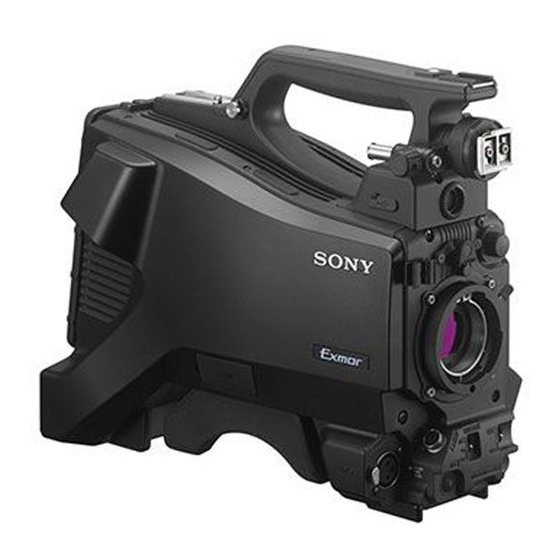
Overview The HXC-FB75 HD Color Camera employs a 2/3-inch type “Exmor” CMOS image sensor that achieves a high sensitivity of F12 (1080/59.94i)/F13 (1080/50i) and high S/N ratio of –60 dB. You can use this unit as a studio camera by connecting it to an HXCU-FB70 Camera Control Unit (CCU) using a fiber cable. -
Page 4: System Configuration
Production of some of the peripherals and related devices shown in the figures may have been discontinued. For advice on choosing devices, please contact your Sony dealer or a Sony service representative. Standalone operation example RCP-1000 series Remote Control Panel... - Page 5 RCP-1000 series Remote Control Panel a) The maximum transmission distance is approximately 350 m (1,150 ft) when using Sony CCFN-25/50/ 100/150/200/250 Hybrid Fiber Cable (with camera head + portable lens). b) A LAN cable can be used only to connect the RCP-1500/1501. To connect it, power needs to be supplied via a PoE hub or power needs to be supplied to the EXT DC IN connector of the RCP-1500/1501.
- Page 6 Remote Control Panel a) The maximum transmission distance is approximately 350 m (1,150 ft) when using Sony CCFN-25/50/ 100/150/200/250 Hybrid Fiber Cable (with camera head + portable lens). b) The maximum transmission distance is approximately 10 km (6 miles) when using general-purpose single-mode fiber cables with LC connectors.
-
Page 7: Name And Function Of Parts
Name and Function of Parts Front and Left Side For the pin assignment of each connector, see “Pin Assignment” (page 53). a Accessory shoe d Microphone holder attachment Attach to a HDVF-L750/HDVF-L770/HDVF-EL75 viewfinder. To For details about attaching, see “Attaching the microphone holder” attach a viewfinder, remove the accessory shoe and attach the shoe (page 23). - Page 8 Lens locking lever Attach a lens. After inserting the lens in the lens mount, rotate the lens mount ring Consult your Sony dealer or a Sony service representative for with this lever to lock the lens in position. information about available lenses.
-
Page 9: Front And Right Side
Front and Right Side Note When connected to a camera control unit or external remote control device • SHUTTER switch (for example, RCP or RM), the following switch functions are controlled • WHT/BLK switch from the connected device. The switches on the camera do not function. •... - Page 10 f RET (return video) button m OUTPUT (output signal select)/AUTO KNEE switch Displays the return video signal in the viewfinder while this button Select the signal that is output from the camera. BARS: Output the color bar signal. is pressed. You can assign a function to this button using FRONT RET on the CAM: Output the video signal being shot.
-
Page 11: Rear
c RET1 (return video 1) button Rear Displays the return video 1 signal in the viewfinder while this button is pressed. For the pin assignment of each connector, see “Pin Assignment” d INTERCOM (intercom volume) knob (page 53). Adjust the intercom volume level. For details about removing the rear cover, see “Removing the rear When connected with the HXCU-FB70, the intercom volume level cover”... -
Page 12: Lens (Supplied With The Hxc-Fb75Kc/Hxc-Fb75Sc)
+48V: To supply +48 V phantom power to condenser microphones Lens (supplied with the HXC-FB75KC/ MIC: When a microphone-level input is connected HXC-FB75SC) LINE: When a line-level (0 dBu) signal source is connected l REMOTE (remote control) connector (8-pin) For details about attaching a lens, see “Attaching and Adjusting the Connect a remote control unit for remote control the camera. -
Page 13: Viewfinder
d Iris one-push auto switch Viewfinder When the iris operation mode selector switch is in the M position for manual adjustment, press this switch for instantaneous auto iris This section describes the HDVF-L10 viewfinder supplied with the adjustment. The iris is automatically adjusted while the switch is HXC-FB75KC. -
Page 14: Connection And Setup
g Tally indicator The indicator lights up when a red tally signal is input to the camera. Connection and Setup When an abnormality occurs, the tally indicator flashes to indicate a warning. h PEAKING knob Rotate clockwise to adjust the picture sharpness to make lens Connecting to a Camera Control Unit focusing easier. -
Page 15: Ac Power Supply (Standalone Operation)
Prepare an AC power supply when using the camera in standalone adaptor mount, and insert the cover. operation mode (without a CCU). For safety, use only the Sony AC adaptor listed below. • AC adaptor: AC-DN10 If using the DC IN connector Connect the AC-DN10 AC adaptor to the DC IN output connector on the camera using an optional DC power cord. -
Page 16: Attaching And Adjusting The Viewfinder
To detach the viewfinder Attaching and Adjusting the Viewfinder Detach in the reverse procedure of attaching. When detaching the viewfinder from the shoe, lift up the slide stopper on the viewfinder. Warning Adjusting the position When the viewfinder is attached, do not leave the camera with the eyepiece facing the sun. - Page 17 To raise the viewfinder barrel To detach the viewfinder barrel 1 Push the clip on the bottom to release it, and 2 flip up the viewfinder barrel. It locks at the 120-degree position. LCD screen Keep in the lock position for normal use. You can also open it farther from the lock position.
- Page 18 Adjusting the diopter Reduced display mode Displays the camera image at a reduced size, with the tally and other Rotate the diopter adjustment ring until the viewfinder image is indicators displayed in the spaces above and below the camera sharpest. image.
-
Page 19: Attaching The Shoe Conversion Bracket
Attach the V-wedge shoe attachment. Attaching the Shoe Conversion Bracket For details about attaching, refer to the operation manual for the viewfinder. Use the shoe conversion bracket when attaching the HDVF-L750 viewfinder supplied with the HXC-FB75SC or the optional HDVF-L770/HDVF-EL75. Using the Camera for the First Time Remove the screw securing the plate spring, and slide the The camera is shipped with the area of use setting in an unset state. -
Page 20: Attaching And Adjusting The Lens
Supported formats: 1080/59.94i, 1080/50i, 1080/29.97PsF, Rotate the menu control knob to scroll the page and align the , pointer with <DATE> and press the menu control 1080/25PsF, 720/59.94P, 720/50P knob. Turn the camera off and then back on. The <DATE> page appears. The camera is now ready for use. - Page 21 The lens supplied with the HXC-FB75KC/HXC-FB75SC is an aberration correction lens. Contact your Sony dealer or a Sony service representative for information about other aberration correction lenses. Adjusting the flange back (flange focal length)
-
Page 22: Preparing The Audio Input
Tighten the F.B. lock screw. Connect the microphone cable to the AUDIO 1 IN connector, and secure with the cable clamp. Preparing the Audio Input Connecting a microphone to the AUDIO 1 IN connector Attach the microphone supplied with the HXC-FB75KC to the microphone holder on the viewfinder. -
Page 23: Mounting On A Tripod
Attaching the microphone holder Place the camera on the tripod adaptor and slide it forward along the groove of the platform until it clicks into place. Remove the screw hole cover from the microphone holder attachment. Move the camera back and forth, and check that it is securely fixed. -
Page 24: Attaching The Shoulder Strap
Attaching the Shoulder Strap Adjusting the Shoulder Pad Position Attach an optional shoulder strap (part number: A-6772-374-C) to You can slide the shoulder pad forward and backward within a the camera. 40 mm (1 5/8 inch) range. This adjustment helps you get the best balance for shooting with the camera on your shoulder. -
Page 25: Shooting
Check the microphone connection and the audio input Shooting selector switch settings (see page 22). Adjust the white balance and black balance (see page 26). Rotate the focus ring on the lens to adjust the focus. Basic Procedure for Shooting Turn the camera on. -
Page 26: Adjustments And Settings
Select the desired format in CURRENT. If an error message is displayed, retry the black balance adjustment. If the error message occurs again, consult your Sony dealer or a Sony service representative. Adjusting the Black Balance and White... -
Page 27: Setting The Electronic Shutter
If an error message is displayed, retry the white balance adjustment. When connected to a camera control unit or external control device (for If the error message occurs again, consult your Sony dealer or a example, RCP or RM), the electronic shutter settings are controlled from the Sony service representative. -
Page 28: Setting Automatic Iris
ECS (Extended Clear Scan) mode Before the shutter setting indication disappears, push the SHUTTER switch to SEL again. Select this mode for obtaining images with no horizontal bands of Repeat this operation until the desired speed is displayed. noise when shooting subjects such as monitor screens. To set ECS mode, select “ECS.”... -
Page 29: Setting The Tlcs Function
Select the <VF DETAIL> page in the OPERATION menu. Setting the TLCS Function <VF DETAIL> 04 TOP You can maintain the proper exposure by using the TLCS (Total VF DETAIL CRISP Level Control System) function. This function controls not only the FREQUENCY iris, but also the shutter (AUTO SHUTTER) and gain (AGC: Auto FLICKER... -
Page 30: Setting The Camera Outputs
Select the <FOCUS ASSIST> page in the OPERATION Setting the Camera Outputs menu. You can specify video signals directly output from the camera using <FOCUS ASSIST> 05 TOP the menu. INDICATOR : OFF MODE LEVEL QUICK Note GAIN OFFSET The MAIN (camera picture), RET (return video), or VF (the same picture as AREA MARKER: OFF that displayed in the viewfinder) settings are common to SD-SDI and VBS. -
Page 31: Adjusting The Audio Level
Outputting the same image as that in the viewfinder Setting the Digital Extender Function With HD-SDI, you can obtain a signal that includes the same information as that being displayed in the viewfinder according to The central area of the screen can be magnified by a factor of 2 or 4 the settings for VF MARKER, CHARACTER, VF DETAIL, by enabling the digital extender function. -
Page 32: Menus
c EX (lens extender) indicator Menus Displayed when using a lens extender. d Zoom position indicator Indicates the approximate position of the zoom lens variator between wide angle (0) and telephoto (99). The menus displayed in the viewfinder enable various settings of the e ! indicator camera. -
Page 33: Operating The Menu
When the STATUS/CANCEL switch is set to <TOP MENU> STATUS USER USER MENU CUSTOMIZE The status display appears when you set the STATUS/CANCEL switch to STATUS with the DISPLAY/MENU switch set to OPERATION PAINT DISPLAY. MAINTENANCE FILE The status screen displays the video format and non-standard DIAGNOSIS settings of the camera. -
Page 34: Selecting A Page
Selecting a Page Setting Menu Items If a ? mark is flashing on the left of the page number, press the menu To select a page from the CONTENTS page control knob to change it to the , pointer. Operation on the Rotate the menu control knob to align the , pointer with the displayed page is enabled. -
Page 35: Editing The User Menu
To return a menu item to the standard value Editing by items When an item is selected and the , pointer is displayed, pressing The USER MENU CUSTOMIZE menu allows you to create a new and holding the menu control knob for 3 seconds restores the setting page for the USER menu and add any item. - Page 36 Move the , pointer to INSERT and press the menu To delete items from a page control knob. The CONTENTS page appears. Move the , pointer to the item to be deleted and press the menu control knob. CONTENTS ?P00 ESC The EDIT FUNCTION screen appears.
-
Page 37: Operation Menu
Select INSERT and press the menu control knob. Move the , pointer to the position where you wish to move The page selection screen appears. the page and press the menu control knob. CONTENTS ITEM MOVE 01.USER 1 01.<VF OUT> 02.USER 2 02.<VF DETAIL>... - Page 38 Page title Item Setting Page title Item Setting Page No. Page No. <‘!’ IND> [IND] <VF MARKER> MARKER ON, OFF Turns the ‘!’ IND indicator function on/off. 02 (U05) 03 (U06) WHITE, BLACK, DOT [NORMAL] LEVEL 0%, 10%, 20%, 30%, 40%, Sets the condition for not displaying the ‘!’...
- Page 39 Page title Item Setting Page title Item Setting Page No. Page No. <FOCUS INDICATOR ON, OFF, (EFFECT) <VF OUT> VF OUT COLOR, Y, R, G, B ASSIST> (EFFECT): Displayed when 08 (U01) RET MIX VF ON, OFF 05 (U03) EFFECT in <VF MIX DIRECTION MAIN, RET MARKER>...
- Page 40 Page title Item Setting Page title Item Setting Page No. Page No. ASSIGN CTEMP OFF, RETURN1 SW, <SWITCH LENS VTR S/S OFF, VTR S/S, RETURN1 RETURN2 SW, RETURN3 ASSIGN2> SW, RETURN2 SW, SW, RETURN4 SW, RETURN3 SW, RETURN4 10 (U10) INCOM , ENG , PROD...
- Page 41 Page title Item Setting Page title Item Setting Page No. Page No. <HEADSET INTERCOM DYNAMIC, CARBON, <INTERCOM> INTERCOM SEPARATE, MIX MIC> MANUAL RECEIVE SELECT 13 (U13) 12 (U12) Displayed when a camera INTERCOM When PANEL TYPE is set adaptor is not connected. to UCJ LEVEL –60dB, –40dB, –20dB...
-
Page 42: Paint Menu
Page title Item Setting PAINT Menu Page No. <EARPHONE> EARPHONE SEPARATE, MIX Page title Item Setting RECEIVE SELECT Page No. INTERCOM When PANEL TYPE is set <SW STATUS> FLARE , OFF to UCJ GAMMA , OFF RIGHT, LEFT, BOTH, --- BLK GAM 0 to 99 KNEE... - Page 43 Page title Item Setting Page title Item Setting Page No. Page No. <GAMMA> LEVEL R/G/B/M: –99 to 99 0 <WHITE CLIP> W CLIP –99 to 99 0 COARSE 0.35 to 0.90 0.45 ON, OFF (0.05 steps) When highlighted (ABS mode): W CLIP is displayed TABLE STANDARD, HYPER in absolute values.
- Page 44 Page title Item Setting Page title Item Setting Page No. Page No. <SKIN DETAIL> SKIN DTL ON, OFF <MULTI PHASE 0, 23, 45, 68, 90, 113, 135, MATRIX> 158, 180, 203, 225, 248, 270, SKIN GATE 1, 2, 3, OFF, (MAT) 293, 315, 338 (MAT): Displayed when Select an axis (angle) for...
-
Page 45: Maintenance Menu
Page title Item Setting MAINTENANCE Menu Page No. <SHUTTER> SHUTTER ON, OFF Page title Item Setting ( ) display: In standalone Page No. operation mode, when an <AUTO SETUP> AUTO BLACK Execute using ENTER. external control device (RCP or RM) is not AUTO WHITE Execute using ENTER. - Page 46 Page title Item Setting Page title Item Setting Page No. Page No. <AUTO IRIS> AUTO IRIS OFF, ON <CIS COMP> FLICKER REDUCE (ON): Displayed when in MODE AUTO, ON, OFF standalone operation FREQ 60Hz, 50Hz mode (not configurable) (Default setting varies with WINDOW 1, 2, 3, 4, 5, 6 region of use.)
- Page 47 Page title Item Setting Page title Item Setting Page No. Page No. <SDI OUT> SDI OUT VF, MAIN, RET, SD-SDI, <WHITE ECC FILTER A, B, C, D, – FILTER> M11 (U17) C and D are displayed only when they are enabled. CHARACTER ON, OFF –: Displayed when...
-
Page 48: File Menu
Page title Item Setting FILE Menu Page No. <REFERENCE> STORE FILE Execute using ENTER. Four types of files can be used for easy adjustments of the camera; Operator, Reference, Scene, and Lens files. Write the current settings of the reference file to internal You can store the items set with the OPERATION menu and memory. -
Page 49: Diagnosis Menu
Page title Item Setting Appendix Page No. <FILE CLEAR> PRESET Execute using ENTER. OPERATOR REFERENCE (ALL) Execute using ENTER. Usage Precautions 10 SEC CLEAR ON, OFF Turn the function for clearing an item selected in a Note on laser beams menu on/off. -
Page 50: Cleaning The Viewfinder
Phenomena specific to CMOS image sensors Security The following phenomena that may appear in images are specific to SONY WILL NOT BE LIABLE FOR DAMAGES OF ANY KIND CMOS (Complementary Metal Oxide Semiconductor) image RESULTING FROM A FAILURE TO IMPLEMENT PROPER sensors. -
Page 51: Supported Usb Flash Drives
Supported USB Flash Drives Specifications Connect a USB flash drive to the USB connector to enable saving General and loading a configuration data file. Power requirements 48 V DC, 1.7 A (max.) 12 V DC (10.5 V to 17.0 V) Pocket Bit LX series USM1GLX, USM2GLX, USM4GLX, USM8GLX, Power consumption... - Page 52 Inputs/outputs Supplied accessories Optoelectric composite connector (1) HXC-FB75H/KC/SC Lens mount cap (1) AUDIO 1 IN XLR type, 3-pin, female (1 each) Test chart for flange focal length adjustment (1) AUDIO 2 IN MIC: –60 dBu (Up to –20 dBu can be set by using Cable clamp belt (1) menu or HXCU-FB70), balanced Shoe conversion bracket (1)
-
Page 53: Pin Assignment
DUE TO FAILURE OF THIS UNIT, EITHER DURING THE WARRANTY PERIOD OR AFTER EXPIRATION OF THE WARRANTY, OR FOR ANY OTHER REASON WHATSOEVER. • SONY WILL NOT BE LIABLE FOR CLAIMS OF ANY KIND MADE BY USERS OF THIS UNIT OR MADE BY Signal THIRD PARTIES. - Page 54 DC IN connector INTERCOM connector Signal Input/ Specifications Signal Input/ Specifications output output Intercom CARBON: –20 dBu, Unbalanced EXT DC (C) – GND for DC (+) MIC (Y)/ DYNAMIC: –60 dBu, Balanced/ – No connection (GND) Unbalanced – No connection MANUAL Intercom MIC (X)
- Page 55 LENS connector 12 11 Signal Input/ Specifications output RET VIDEO ENABLE: 0 V ENABLE DISABLE: +5 V or OPEN VTR CTL ENABLE: 0 V DISABLE: +5 V or OPEN – GND for UNREG SERVO MA/ AUTO: +5 V MANU: 0 V or OPEN IRIS +3.4 V (F16) to +6.2 V (F2.8) POSITION...
-
Page 56: Menu Tree
Menu Tree OPERATION PAINT DETAIL 2 (P10) VF DISPLAY (01) SWITCH ASSIGN1 (09) SW STATUS (P01) GAIN FLARE H/V RATIO ZOOM ASSIGNABLE1 GAMMA FREQ FOCUS MIX RATIO ASSIGNABLE2 BLK GAM ASSIGNABLE3 KNEE KNEE APT ASSIGN CTEMP WHT CLIP DTL H/V MODE RE.ROTATION DETAIL 5600K... - Page 57 FILE DIAGNOSIS MAINTENANCE AUTO SETUP (M01) DATE (M14) OPERATOR FILE (F01) TRANSMISSION CONDITION (D01) AUTO BLACK DATE/TIME READ (USBtCAM) OPTICAL LEVEL AUTO WHITE FILE TIMESTAMP FORMAT WRITE (CAMtUSB) DC INPUT LEVEL AUTO LEVEL BATTERY ALARM (M15) PRESET BOARD STATUS (D02) AUTO WHITE SHADING BEFORE END STORE PRESET FILE...
-
Page 58: Open Software Licenses
Open Software Licenses On the basis of license contracts between Sony and the software copyright holders, this product uses open software. To meet the requirements of the software copyright holders, Sony is obligated to inform you of the content of these licenses.