Kenwood TM-255A Product Manual
Multi-communicator vhf/uhf fm dual bander getting acquainted with aprs and echolink
Hide thumbs
Also See for TM-255A:
- Instruction manual (66 pages) ,
- Service manual (110 pages) ,
- Instruction manual (60 pages)

Related Manuals for Kenwood TM-255A


Summary of Contents for Kenwood TM-255A
- Page 1 TM-D710A/E Multi-communicator VHF/UHF FM Dual Bander Getting Acquainted with APRS and EchoLink...
-
Page 2: About This Manual
• TM-D710A/E and RC-D710 with firmware version 2.00. Software License Notice • Users are required to obtain approval from Kenwood, in writing, prior to redistributing this document on a personal web page or via packet communication. • Users are prohibited from assigning, renting, leasing or reselling the document. - Page 3 ® • NAVITRA is a registered trademark of Kenwood Corporation. • Kenwood is a licensed user of the APRS trademark and protocols from APRS Engineering, LLC. ® • APRS is a registered trademark of WB4APR (Bob Bruninga). • TravelPlus for Repeaters™ is a registered trademark of American Radio Relay League, Inc.
- Page 4 This page is intentionally left blank.
-
Page 5: Table Of Contents
Situational Awareness ...4 2.1.5 Participation ...4 Ubiquitous Operations... 5 APRS Global Internet System ... 5 Kenwood Contributions ... 6 APRS in the Field ... 7 Other Data Entry Stations ... 8 3 PREPARATIONS FOR USING APRS ...9 What Do I Need to Configure? ... 9 Configuration ... - Page 6 CONTENTS Digipeaters (Digital Repeaters)... 34 7.4.1 UIDIGI... 34 7.4.2 UIFLOOD... 35 7.4.3 UITRACE ... 35 7.4.4 Configuration Examples (U.S.A.)... 36 7.4.5 Proper Configuration (written by Bob Bruninga, WB4APR) ... 37 Packet Path... 38 7.5.1 New-N Paradigm ... 38 7.5.2 RELAY Paradigm... 38 7.5.3 STATE/ SECTION/ REGION ...
- Page 7 9.5.3.7 Transceiver Menu > Variable Level of Data Terminal... 75 9.5.3.8 Transceiver Menu > SQC Output Logic ... 75 9.5.4 Unique Functions...76 9.5.4.1 Importing TravelPlus for Repeaters Files ... 76 9.5.4.2 Importing .hmk Files ... 76 9.5.4.3 Exporting .hmk Files... 76 9.5.4.4 Exporting .html Files...
- Page 8 This page is intentionally left blank.
- Page 9 Complementing these voice and data activities is the Automatic Packet Reporting System, commonly called APRS. Mr. Bob Bruninga WB4APR created APRS back in 1992. Since those days of first meeting with Bob, Kenwood married radio and GPS technology and our company developed APRS products over the years.
- Page 10 New Technology Expands Amateur Radio Versatility Using HF radio to call CQ and contact hams around the world will never lose its appeal. But there is elegance in being able to communicate with only an FM transceiver and by adopting the latest technology.
-
Page 11: Development Concept
At this stage, our goal to have a TNC with APRS functionality was realized. We merchandised the standalone front panel with the underlying concept of allowing existing Kenwood customers to enjoy the benefits of APRS. TM-D710A/E... -
Page 12: Evolving Development
1 DEVELOPMENT CONCEPT 1.2 Evolving Development In order to develop an APRS model following the TM-D700 series, we discussed face-to-face directly with Mr. Bob Bruninga, developer of APRS, an operation specification to better implement the flexibility of the APRS protocol. We were going to “kick it up a notch” and make APRS still more powerful. -
Page 13: Aprs Operations Written By Bob Bruninga, Wb4Apr
2 APRS OPERATIONS written by Bob Bruninga, WB4APR 2.1 APRS Overview 2.1.1 History APRS was developed beginning back in the 1980s by Bob Bruninga, WB4APR, as a real-time local tactical communications system for rapidly exchanging digital data of immediate value to local operations. -
Page 14: Mobile Information Resource
APRS was never intended to be just a vehicle tracking system (GPS was added in the 1992 time frame when GPS became affordable). APRS is much more. See the Kenwood mobile display below. This is the STATION LIST which shows the nearest 100 stations heard. In this case, not only are the two stations of AB9FX nearby, but also his current voice operating frequency is visible. -
Page 15: Ubiquitous Operations
2.2 Ubiquitous Operations Consistent with providing information on all resources within range, APRS must also work across all boundaries and in all areas of the continent for all travelers. For this reason, 144.39 MHz is dedicated to APRS throughout North America. Other continents have similar single frequencies such as 144.80 MHz in Europe and 145.175 MHz in Australia. -
Page 16: Kenwood Contributions
These two techniques provide good refresh rates for new and local information while minimizing the network impact of old and distant data. • Objects: The Kenwood transceivers fully appreciate the value of APRS objects and display them prominently. The object location is shown just like other stations either on the attached map display or on the front panel with distance and range. -
Page 17: Aprs In The Field
TM-D710A/E TUNE button will QSY instantly if needed. • Voice Alert: Voice alert is like a 3rd simultaneous radio channel on the Kenwood APRS transceivers. It acts like an intercom channel for all APRS operators to be able to quickly raise another nearby APRS voice alert station by a simple direct voice call. -
Page 18: Other Data Entry Stations
2 APRS OPERATIONS written by Bob Bruninga, WB4APR 2.6 Other Data Entry Stations But we should not lose sight of the home station that can also be used as a great information resource. The next photo shows a station that was set up in a motel room and the operators there could monitor all of the activities on the various nets and enter this situational information into their APRS PCs. -
Page 19: Preparations For Using Aprs
3 PREPARATIONS FOR USING APRS 3.1 What Do I Need to Configure? The following need to be configured before beginning to operate TM-D710A/E or RC-D710 with APRS. • Built-in Clock APRS data will be stamped with date and time, therefore the built-in clock must be set. •... -
Page 20: My Callsign
3 PREPARATIONS FOR USING APRS Select Menu 525 (AUX - TIME) and configure the current time. Example: Configure the time 12:00. Refer to Figure 3-2. Figure 3-2 Menu 525 (AUX - TIME) Select Menu 526 (AUX - TIME ZONE) and configure your time zone. 3.2.2 MY CALLSIGN Select Menu 600 (APRS - BASIC SETTINGS - MY CALLSIGN) and configure your own callsign. -
Page 21: My Position
3 PREPARATIONS FOR USING APRS 3.2.4 My Position 3.2.4.1 Activating Your Mobile GPS Position Select Menu 602 (APRS - GPS PORT) and configure the GPS terminal settings. • Baud Rate: 4800 bps (same as GPS receiver) • Input: GPS (for the GPS receiver) •... -
Page 22: Setting The Aprs Channel
3 PREPARATIONS FOR USING APRS 3.2.5 Setting the APRS Channel Example: Configure a frequency of 144.390 MHz. Refer to Figure 3-8. Figure 3-8 Operating Frequency TM-D710A/E CONTENTS... -
Page 23: Position Determination Principle
4 GPS 4.1 What is GPS? GPS, standing for Global Positioning System, is becoming common nowadays. Following is a brief introduction. The American Defense Department developed GPS originally for military operations. The system is available for use by the general public. For example, anybody can use GPS in association with modern vehicle navigation systems. -
Page 24: Datum (Geodetic Survey System)
4 GPS 4.1.2 Datum (Geodetic Survey System) The latitude and longitude information required by the GPS receiver does not allow for accurate representation of the unevenness of the Earth’s surface. For use with GPS, the current standard that defines the precise shape of the Earth is called WGS-84. By using this standard in conjunction with mapping standards for each country, accurate position plotting on a map can be done. -
Page 25: Gps Receivers
Because there is no screen, you cannot use the Waypoint function. 4.2.2 AvMap G5 The AvMap G5 comes with a Kenwood-ready cable and exclusive APRS interface built right into the panel. You can watch APRS activity on the AvMap G5 screen without having a PC. It can be also configured to navigate to your favorite APRS station. -
Page 26: Aprs Software For Your Pc
5 APRS SOFTWARE FOR YOUR PC 5.1 UI-View 5.1.1 Introduction to UI-View UI-View32 is APRS client software designed to allow a personal computer to display APRS stations on a map and to use various APRS functions such as Internet gateway access. So you can display on a map on your computer the APRS stations received by a TM-D710A/E and, in addition, connect to an Internet gateway. -
Page 27: Connecting A Pc
TM-D710A/E. TM-D710A/E Initialization File ;This is a sample TNC initialization file for use with ;the Kenwood TM-D710A/E. [SETUP] ;DON'T alter anything in this section unless you are ;sure you know what you are doing! -
Page 28: Available Aprs-Related Software
5 APRS SOFTWARE FOR YOUR PC 5.2 Available APRS-related Software The APRS program currently runs on a number of platforms. These programs are constantly being updated and can be downloaded from the Internet. Most programs are shareware and the latest versions are available at the TAPR (Tucson Amateur Packet Radio) FTP site: ftp:// ftp.tapr.org/aprssig. -
Page 29: Aprs In Action
6 APRS IN ACTION While monitoring APRS stations from around the world that may appear on your map, you can easily send messages to them. An interest is now growing in APRS QSOs where one station may call CQ looking for responses in the conventional style of a ham contact. Due to the number of characters being restricted, it can be customary to send short sentences using abbreviated words similar to operating CW. -
Page 30: Proportional Pathing Function
6 APRS IN ACTION 6.1.2 Decay Algorithm Function The position beacon for a mobile station is usually transmitted at a fixed time interval to provide consistency in vehicle tracking and station participation. However, when traffic is slow-moving, it would be inefficient use of air-time to continue transmitting at this fixed interval. Therefore, while parked or moving slowly, the beacon transmission interval gradually increases by using a decay algorithm. -
Page 31: Simultaneously Using Decay Algorithm And Proportional Pathing
6.1.4 Simultaneously using Decay Algorithm and Proportional Pathing Refer to the diagram below to understand what occurs when both Decay Algorithm and Proportional Pathing are used at the same time. Velocity (Knots) Decay Status Figure 6-3 Switching between Decay Algorithm and Proportional Pathing As the example above shows, when the mobile’s speed exceeds 3 knots, Decay Algorithm stops and Proportional Pathing begins. - Page 32 6 APRS IN ACTION (with LOW SPEED = 5, HIGH SPEED = 70, SLOW RATE = 30 min, FAST RATE = 120 sec) Speed (min.) Note: The unit of Speed can be configured by using Menu 626. CONTENTS Table 6-2 Configuration Example Menu Item Configured Value LOW SPEED...
-
Page 33: Corner Pegging (Transmission After Heading Change)
6.1.5.2 Corner Pegging (Transmission after Heading Change) When the mobile station’s speed is above LOW SPEED, Corner Pegging begins operating. A Corner Pegging position beacon will be transmitted when the heading difference exceeds the TURN THRESHOLD value. The heading difference is the compass heading of the present direction of travel (in degrees) subtracted from the compass heading transmitted in the previous position beacon. -
Page 34: Operation Example
6 APRS IN ACTION Table 6-6 Corner Pegging Operation Example: Speed TURN SLOPE (Cut off after the decimal point) (1) 26 (x10) 26 (x10) 26 (x10) 26 (x10) 26 (x10) 26 (x10) 26 (x10) 26 (x10) 26 (x10) 26 (x10) Note: When TURN THRESHOLD exceeds 120 degrees, the value will be corrected to 120 degrees. -
Page 35: Qsy Function
6.1.6 QSY Function The QSY function uses AFRS (Automatic Frequency Reporting System) to report a frequency on which voice communications can be established. A station using the QSY function embeds the frequency information in a position beacon transmission. A receiving station of this information can change frequency, or QSY, over to the reported voice frequency to begin voice communication by the press of [TUNE] on the TM-D710A/E. - Page 36 6 APRS IN ACTION Configuration Examples: (Insert one space after the frequency before entering Wide/Narrow, Tone/CTCSS/DCS and Shift/ Offset.) • “446.100MHz”: Voice frequency configured for 446.100 MHz, Wide, Tone = None, Simplex • “446.100MHz T071”: Voice frequency configured for 446.100 MHz, Wide, Tone of 71.9 Hz, Simplex •...
-
Page 37: Receiving Qsy Information
6 APRS IN ACTION 6.1.6.2 Receiving QSY Information The TM-D710A/E receives QSY information not only from another TM-D710A/E, but also location information from other software as well as QSY information and repeater frequency object information embedded in status text. You can confirm the QSY information that is received as embedded data by checking the voice frequency at the beginning of the status text on the Station List screen. -
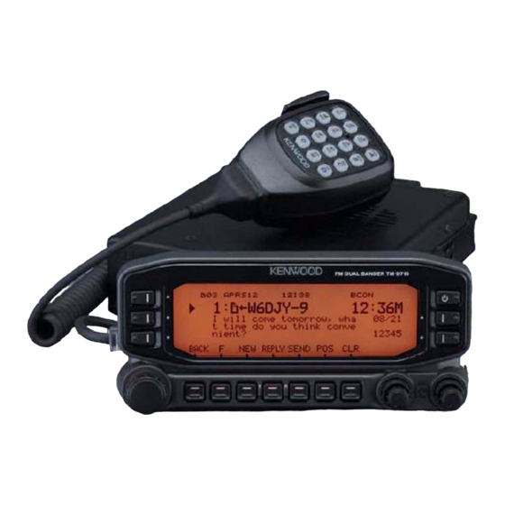
Page 38: Automatic Reply Message
6 APRS IN ACTION 6.1.7.1 Automatic Reply Message The Automatic Reply Message function replies to messages that you receive while you are driving. You can pre-configure a message response such as “I am QRX. Will return at 12:35.”. When using TH-D7A/E or TM-D700A/E, a response message was returned to all message senders. -
Page 39: Base Station (Weather Station)
6 APRS IN ACTION 6.2 Base Station (Weather Station) Weather observation equipment intended for use at home is becoming more common. Using this equipment, you can observe and measure wind direction, wind velocity, air temperature, humidity, rainfall, atmospheric pressure, etc. This information can be useful to others when the data is gathered and transmitted in real time via APRS beacon transmissions. -
Page 40: Peet Bros. Company, Inc
6 APRS IN ACTION 6.2.1.2 Peet Bros. Company, Inc. The weather station, ULTIMETER 2100 from Peet Bros. Company shop/item.aspx?itemid=2) can also be used with TM-D710A/E or RC-D710. To communicate with ULTIMETER 2100, configure the TM-D710A/E communication baud rate (Menu 602) to 2400 bps. Note: Because the GPS receiver and the weather observation equipment use the same connector, combined use is not possible. -
Page 41: Aprs Networks
7 APRS NETWORKS 7.1 Servers In the beginning, APRS networks consisted only of general packet transmissions through digital repeaters. To expand network coverage much further, HF gateway stations that were interfaced with the VHF stations were added. This arrangement evolved still further when it became common for personal computers to be connected with the Internet. - Page 42 7 APRS NETWORKS Tier 2 Tier 2 Server Server IGate Core Server IGate Client Tier 2 Server Core Server Core Server IGate IGate Tier 2 Server IGate Tier 2 Client Server IGate IGate IGate IGate Figure 7-1 APRS Network Conceptual Drawing TM-D710A/E CONTENTS...
-
Page 43: Let's Send Email
7.3 Let’s Send Email With TM-D710A/E and RC-D710 it is possible to transmit email by using the Message function. 7.3.1 Sending Email with TM-D710A/E and RC-D710 First, press [MSG] to show the Message List on the screen. Next, press [NEW] to create a message on the screen. -
Page 44: Uidigi
7 APRS NETWORKS 7.4 Digipeaters (Digital Repeaters) The greatest feature of APRS is the network that is spreading around the world. The heart of the network is made up of many digital repeaters commonly referred to as digipeaters. Of course, digipeaters are well-known among those who have used packet radio for years. - Page 45 7.4.2 UIFLOOD With UIFLOOD activated (On), when a digipeater receives a UI frame with a character string for alias in the form XXXXn-N where XXXX matches the alias character string in the digipeater, the digipeater subtracts 1 from N and processes the packet reporting only the revised character string so as not to make the frame length too long.
-
Page 46: Configuration Examples (U.s.a.)
7 APRS NETWORKS Although UITRACE using the normal APRS network path of WIDEn-N can be a problem if mobiles activate their digipeater at the wrong time, it is also so powerful, that it is a shame not to be able to use it easily if required. - Page 47 7 APRS NETWORKS UIDIGI UIDIGI: ON ALIAS: SAR (other local paths can be defined here) Note: SAR stands for “Search and Rescue”. UIFLOOD UIFLOOD: ON ALIAS: SS or SSS SUBSTITUTION: ID (where SS or SSS is the abbreviation of state or ARRL section) UITRACE UITRACE: ON ALIAS: WIDE...
-
Page 48: Packet Path
7 APRS NETWORKS 7.5 Packet Path It is necessary to confront the issue of frequency congestion due to the spread of APRS systems in order to efficiently transfer packet data. The TM-D710A/E supports the configurations of New-N Paradigm, RELAY Paradigm and STATE/SECTION/REGION. Overall, this provides an efficient mechanism for transferring packets. -
Page 49: Using Aprs And Echolink Simultaneously
7.6 Using APRS and EchoLink Simultaneously Both EchoLink Sysop mode and APRS/Packet mode using the internal TNC can be used at the same time. This means that a single TM-D710A/E transceiver can serve as an EchoLink node station and APRS/Packet station to transmit beacons or work as a digipeater simultaneously. To operate in EchoLink Sysop mode and use the APRS/Packet station with a single TM-D710A/E transceiver, assign a different band for the external data band (Menu 517) for EchoLink and the internal data band for Packet (Menu 529) or for APRS (Menu 601). -
Page 50: What Is Echolink
8 EchoLink 8.1 What is EchoLink? EchoLink is a system that links amateur radio stations together using the Internet and allows amateur radio operators to enjoy speech communication with other operators via this worldwide network. EchoLink Server PC User Link Station Repeater Station (Simplex) (Semi-Duplex) -
Page 51: Making The Connections
TM-D710A/E’s transmitter, and to detect the presence of a signal received by the TM-D710A/E. 8.2.2 Making the Connections The Kenwood PG-5H is a package of two different cables. Following the instructions in the TM-D710A/E Instruction Manual, connect the cables to the two jacks in the back of the transceiver and to the serial port and sound card jacks of your computer. - Page 52 If that’s the case, the audio output level from TM-D710A/E can be adjusted using the MCP-2A software, downloadable from the Kenwood Support Web site. Once you have the MCP-2A program up and running, go to the Data Terminal Adjustment section, and increase the PR1 Output Level (EchoLink Mode) from 3 to a higher value such as 6 or 7.
- Page 53 8 EchoLink 8.3 Using EchoLink only with Amateur Radio Equipment If there is an EchoLink node within range of your transceiver, it is possible for you to access the node and communicate via your transceiver with distant stations using the node. You can search for nearby nodes at the EchoLink site at http://www.echolink.org.
- Page 54 8 EchoLink Figure 8-4 Finding Nearby EchoLink Nodes Selecting “Online Only” in the pulldown list to the left of the “Find” button results in search results being displayed only for those nodes currently connected to the EchoLink server. “-L” at the end of a node callsign, such as “W4DJY-L”, indicates a link station (simplex operation). “-R”...
- Page 55 8.3.1 Basic Commands used for EchoLink Command Connect Connects to a station on the Internet, based on its node number. Connect by Call Connects to a station on the Internet, based on its callsign. Disconnects the station that is currently connected. If more than one station is Disconnect connected, disconnects only the most-recently-connected station.
- Page 56 8 EchoLink 8.3.2.2 Transmitting with an EchoLink Memory 1. Press the PTT switch to transmit. 2. Press the Tuning Control while transmitting. • The transceiver enters the EchoLink memory channel selection mode. 3. Turn the Tuning Control while the PTT switch is pressed to select the EchoLink memory channel on which you want to transmit.
-
Page 57: Downloading Echolink Software
8 EchoLink 8.4 Using EchoLink only with a Computer If the EchoLink software is installed on your personal computer, without using any transceiver, it is possible to communicate as a single user directly via your personal computer. In addition, when you set up a link station, by connecting a TM-D710A/E and a personal computer, we recommend you make it possible to use EchoLink software in Single User mode as an advanced preparation. -
Page 58: Installing Echolink Software
8 EchoLink The Download EchoLink page with a download link will appear. Double click “Click Here to Download”. The download will begin. Figure 8-8 EchoLink Software Download Security Warning Select the appropriate folder and save the file to this folder. 8.4.2 Installing EchoLink Software Click the icon of the file you downloaded called “EchoLinkSetup_X_X_XXX.exe”... - Page 59 8 EchoLink Figure 8-10 EchoLink User Type Select “Computer User” and then click the “Next >” button. Figure 8-11 Type of Connection Unless you are using an analog modem (56k or less) to dial up to an ISP (Internet Service Provider), select “DSL, cable, ISDN, or other (above 56k)”...
-
Page 60: Validation Of Echolink User's Callsign
8 EchoLink Figure 8-13 Setup Complete Window Click the “Finish” button. Figure 8-14 Validation Advisory Window When validation of your callsign is necessary, a validation advisory window will appear. Click the “OK” button and proceed to the Validation procedure. 8.4.4 Validation of EchoLink User’s Callsign Begin the EchoLink Validation process by clicking “Validation”... - Page 61 8 EchoLink Enter your callsign and click the “Continue” button. The callsigns available for validation will appear. Figure 8-16 Callsigns Available Page When the software was configured via the Setup Wizard as a Computer User, only your callsign (without -L or R at end of callsign) is shown to represent a single user. Confirm the callsign is selected (small black circle to left of callsign).
-
Page 62: Scan And Upload
8 EchoLink 8.4.4.1 Scan and Upload Use a digital camera or scanner to create a graphics file of your license. Click “Scan and Upload”. Enter the necessary information and upload the license file. Note: Be sure to follow the tips below: •... -
Page 63: Setting Audio Levels
8 EchoLink Stations that are currently connected to EchoLink will appear on the screen. This screen will automatically update as changes occur. Figure 8-20 EchoLink Startup Window 8.4.6 Setting Audio Levels Before starting to make QSOs, first connect to the Test Server and configure the correct receive volume. -
Page 64: Adjusting Receive Volume
8 EchoLink 8.4.6.1 Adjusting Receive Volume Adjust the receive volume of the announcement audio from the test server. Select “Adjust Sound Device” > “Playback...” from the Tools pulldown menu. Figure 8-22 Receive Volume Menu Selection Adjust the appropriate volume control using the test server announcement. 8.4.6.2 Adjusting Transmit Level Adjust the level of the transmit audio that is sent from the microphone to the test server. -
Page 65: Connecting With A Station
8.4.7 Connecting with a Station Connected stations are listed in the Station List of the Index View tab on the EchoLink software screen. The stations are listed in order of repeater stations, link stations, single user stations (PC users) and conferences in the chart. First, choose a single user station and connect to it. If connecting to a repeater station, link station or conference, before pressing the space bar to transmit, monitor sufficiently to understand who else may already be connected. -
Page 66: Setting Up A Node Station Link Station) With Tm-D710A/E
TM-D710A/E’s transmitter, and to detect the presence of a signal received by the TM-D710A/E. 8.5.1 Connecting a PC The Kenwood PG-5H is a package of two different cables. Following the instructions in the TM-D710A/E Instruction Manual, connect the cables to the two jacks on the back of the transceiver and to the serial port and sound card jacks of your computer. -
Page 67: Configuring Echolink Software For A Link Station
8 EchoLink 8.5.2 Configuring EchoLink Software for a Link Station If your computer is already configured for use in Single User mode of EchoLink, you can easily set up a link station. Select “Setup...” from the Tools pulldown menu to open the System Setup window. - Page 68 8 EchoLink Figure 8-29 Changing Callsign to be a Link Station Enter in the Callsign edit box your callsign with -L at the end such as W6DJY-L. Click the “OK” button. A server message will display that indicates the new callsign must be validated. You must close the EchoLink software and validate this new callsign as a link station.
- Page 69 8 EchoLink Figure 8-31 EchoLink Validation Page Enter your callsign and click the “Continue” button. The callsigns available for validation will appear. Figure 8-32 Callsigns Available Page Confirm the callsign is selected (small black circle to left of callsign). This callsign becomes the validation object.
- Page 70 8 EchoLink Click “Password”. The page shown in Figure 8-34 appears. Figure 8-34 Password Entry Page Select the new link station, enter the password you configured during the first validation process and click the “Continue” button. “Verifying password...” will display, and then “Password verified” will display within 1 minute.
- Page 71 8 EchoLink Figure 8-37 Sysop Setup Window: RX Ctrl Tab Select the “Serial CTS” radio button in the Carrier Detect frame. Configure the “Serial Port” dropdown list for the port used for EchoLink. Confirm the correct serial port to use by examining your computer configuration;...
- Page 72 8 EchoLink Figure 8-39 Sysop Setup Window: DTMF Tab Select the Internal radio button in the DTMF Decoder frame. In order for you to administer your link station, we recommend that you input a DTMF command for LinkDown and LinkUp for the EchoLink server.
- Page 73 8 EchoLink Figure 8-41 Sysop Setup Window: Options Tab The initial settings are fine to use. No changes are necessary. Finally, click the RF Info tab. Figure 8-42 Sysop Setup Window: RF Info Tab At this point, you must enter your link station information. While initially experimenting and setting up your station, it’s best not to enter this information.
-
Page 74: Finding Your Position (Latitude Longitude Coordinates)
8 EchoLink When operational frequency, Tone frequency, etc. are modified, after you connect to the EchoLink server, all modified information will be transferred at one time. Click the “OK” button to complete the settings. 8.5.2.1 Finding your Position (Latitude/ Longitude Coordinates) Besides using a GPS receiver, it is possible to use web sites on the Internet and software to acquire your latitude and longitude coordinates. -
Page 75: Using Mcp-2A To Configure Tm-D710A/E
To PC audio terminal PG-5H Cable Kit Pink: To microphone input terminal Green: To line out terminal To PC 9-pin D-SUB terminal Figure 8-43 Computer to TM-D710A/E Connections 1. Turn the power OFF. 2. Hold [PF2] down and turn the power ON. Whenever Steps 1 and 2 are done, the EchoLink Sysop mode turns On and Off. - Page 76 8 EchoLink 3. Select “Menu” > “Transmit/Receive” from the Edit pulldown menu. When using CTCSS or DCS for the purpose of preventing extraneous signals or noise from being fed into the Internet from a link station, configure “EchoLink RX Monitor” for “Busy Only” in the dropdown list. When EchoLink Sysop mode is used, all signals received on the data band are output from the speaker regardless whether CTCSS or DCS has matched;...
-
Page 77: Checking Your Link Station
Note: Steps 3 through 5 above can only be done using MCP-2A. Older versions of MCP-2A may not have menu items described above. In this case, upgrade your MCP-2A to version 3.10 or newer. 8.5.5 Checking your Link Station Here are the steps to follow to check out your link station: •... -
Page 78: Downloading And Installing Mcp-2A
Details of USB-to-serial conversion for use with APRS and TM-D710A/E can be obtained from the amateur radio community. 2. Download the newest version of MCP-2A from the Kenwood web site URL shown below (URL is subject to change). MCP-2A download location: amateur/mcp_2a.html... - Page 79 Windows Vista does not require Microsoft .NET Framework 2.0 (or later) since this newer version of Windows already contains the necessary environment software. 4. Click “Start” > “Program” > “KENWOOD” > “MCP-2A” to start MCP-2A. When MCP-2A starts, the transceiver model is requested. Select the correct transceiver model and click the “OK”...
- Page 80 9 MCP-2A Memory Control Program (for use with TM-V71A/E, TM-D710A/E, RC-D710) 6. Finish the installation. The fact that information is read from the target transceiver completes the MCP-2A installation. Click the “OK” button, select “Read Data from the Transceiver” from the Program pulldown menu and read the information from the target transceiver.
-
Page 81: Main Functions Of Mcp-2A
9 MCP-2A Memory Control Program (for use with TM-V71A/E, TM-D710A/E, RC-D710) 9.2 Main Functions of MCP-2A MCP-2A has many functions. This section lists the most commonly used functions of MCP-2A including importing files. 9.2.1 Main New Functions Added • Imports and exports memory channels. •... -
Page 82: Importing Other Mcp Files Into Mcp-2A
The files that were created by other MCP programs (except J-type) in the table below can be imported into MCP-2A. The referenced software can be downloaded from the following web site: http://www.kenwood.com/i/products/info/amateur/software_download.html. Table 9-2 MCP-2A Importable File Formats Table Software Name... -
Page 83: Importing .Hmk Files Created By Another Mcp-2A
9 MCP-2A Memory Control Program (for use with TM-V71A/E, TM-D710A/E, RC-D710) Table 9-3 MCP-2A Importable File Formats Table (K-type only) Software Name and Transceiver Extension Model MCP-G707 (*.707) TM-G707A MCP-V7 (*.v7) TM-V7A MCP-G71 (*.71) TH-G71A Note: MCP-2A is unable to read memory channels that cannot be received by using TM-V71A/E and TM-D710A/E. With MCP-2A, it is not possible to exchange data between above-mentioned transceivers except TM-V71A/E or TM-D710A/E. -
Page 84: Other Functions
9 MCP-2A Memory Control Program (for use with TM-V71A/E, TM-D710A/E, RC-D710) 9.5 Other Functions 9.5.1 Basic Functions Using MCP-2A, it is possible to configure almost all transceiver functions as were configured with MCP-1A. And, too, there are unique functions that can only be configured with MCP-2A. Category Memory channels, Program Memory channels, Call channels, Train channels/ Weather Memory Frequencies... -
Page 85: Menu Settings
9 MCP-2A Memory Control Program (for use with TM-V71A/E, TM-D710A/E, RC-D710) 9.5.3 Menu Settings 9.5.3.1 Transceiver Menu > EchoLink RX Monitor When using the transceiver in EchoLink Sysop mode, output from the speaker and output to the data terminal can be configured. This function is only possible to configure with the MCP-2A. 9.5.3.2 Transceiver Menu >... -
Page 86: Files
9.5.4.3 Exporting .hmk Files It is possible to export a file that was created using Kenwood .hmk format. Refer to the MCP-2A Help file for details as to how to use a .hmk file that was imported as explained in Section 9.4 Importing .hmk Files Created by Another MCP-2A. -
Page 87: Verifying Firmware Versions
9 MCP-2A Memory Control Program (for use with TM-V71A/E, TM-D710A/E, RC-D710) 9.5.5 Useful Functions 9.5.5.1 Verifying Firmware Versions First, connect the transceiver or operation panel to the computer, and then turn the transceiver or operation panel ON. Select “Product Information” from the Model dropdown menu. The transceiver firmware version will appear on the MCP-2A. -
Page 88: Memory Channel Shortcut
9 MCP-2A Memory Control Program (for use with TM-V71A/E, TM-D710A/E, RC-D710) 9.5.5.6 Memory Channel Shortcut The memory channel shortcut can be used as follows: • Double-click “Free Memory Channel: xxxx/1000” on the Status bar (see Figure 9-8). The Memory Channel window will appear. The memory channel shortcut can be used as follows: Furthermore, if the following action is done, the configuration window will open to allow configurations to be entered:... -
Page 89: How To Update Firmware
• Communication cable (PG-5G or PG-5H) • Firmware update program Kenwood provides the firmware update program for use on Windows operating systems. The specifications for your computer in order to use this software are as shown in Table 10-1. Table 10-1 Firmware Update Computer Specifications Table... -
Page 90: How To Verify Firmware Version
10 HOW TO UPDATE FIRMWARE 10.3 How to Verify Firmware Version You can verify the firmware version by the procedure below. Use one of the following two ways of verifying. 10.3.1 Checking the Transceiver Operation Panel 1. Press [TNC] on TM-D710A/E or RC-D710 to display “APRSxx”. (Skip this step for TM-V71A/E) 2. -
Page 91: Firmware Update For Smartbeaconing And Other Enhancements
New firmware is required to use the SmartBeaconing function in the following cases: • If transceiver and controller version is older than Version 2.00 10.4 How to Get Newest Firmware/Software Download the newest version of update software from the Kenwood web site URL shown below (URL is subject to change). http://www.kenwood.com/i/products/info/amateur/software_download.html 10.5 How to Update... -
Page 92: Miscellaneous Topics
Note: 1200/9600 bps data communications functionality is possible via the 6-pin mini-DIN connector. However, this type of data operation cannot be guaranteed for these transceivers. Furthermore, when RC-D710 is connected to equipment other than the above mentioned transceivers, Kenwood cannot support nor offer an opinion as to whether such configurations will function. -
Page 93: Rc-D710 To Tm-D700A/E Tm-V708A
11.1.1.2 Connection Example 2: Connecting RC-D710 to TM-D700A/E, TM-V708A Transceiver DATA terminal Line filter Panel jack Figure 11-2 Connecting RC-D710 to TM-D700A/E, TM-V708A Note: Excluding the situation of using the RC-D710 as the operating panel for TM-V71A/E or TM-D710A/E, the RC-D710 cannot operate transceivers. - Page 94 11 MISCELLANEOUS TOPICS 11.2 Adjusting Input and Output Levels When a transceiver, other than those that have been verified to operate correctly, is connected, there are times when adjustment of input/output levels may become necessary for RC-D710 and the transceiver to function properly. Even when you cannot adjust the input and output levels on the transceiver side that is connected, it is possible to adjust input and output levels on the RC-D710 side using 3dB steps by using MCP-2A.
- Page 95 GPS unit. The transceiver has three formats for interfacing to GPS units: NMEA, Magellan and the new Kenwood format. A GPS system with a serial interface will connect to the TM-D710A/E but if your GPS supports bi-directional communication, it is possible to have APRS callsigns and icons appear on the GPS screen.
- Page 96 AvMap G5 operating system. When the mark is made on the screen, it now can be one of over 100 standardized APRS icons along with the callsign. Setup of the Kenwood transceiver with AvMap is very simple. Using the defaults of the Kenwood transceiver, only a few menu configurations are needed to set up the TM-D710A/E.
- Page 97 APRS activity is stored in the APRS subfolder of the contacts folder for easy reference so you can navigate to it or monitor a particular APRS callsign in Tactical Mode. With the Kenwood TM-D710A/E and AvMap G5, there is no need to mess around with USB to serial converters nor is there need for a cumbersome computer.
-
Page 98: Revision History
11.1.1 Models Supported for use with RC-D710 and 11.4 AvMap. 4) Revised the descriptions in Amateurs Building the New Global Communications Network, 2.2 Ubiquitous Operation, 2.4 Kenwood Contributions, 3.1 What Do I Need to Configure, 3.2.1 Built-in Clock, 3.2.3 BEACON TYPE, 4.1 What is GPS?, 5.1.3 Creating a CMD File for TM-D710A/E,... - Page 99 We would like to extend our thanks to the following people who helped compile this booklet: WB4APR Mr. Bob Bruninga, K1RFD Mr. Jonathan Taylor, KA9MVA Mr. Steve Bragg and W6GPS Mr. Don Arnold Also, we would like to thank all hams who support and maintain the APRS and EchoLink network in the world.
- Page 100 Revision 1.01 May 16, 2008...