Table of Contents
Advertisement
Advertisement
Chapters
Table of Contents

Related Manuals for Kyocera FaxSystem(M)


Summary of Contents for Kyocera FaxSystem(M)
- Page 1 FaxSystem(M) SERVICE MANUAL Published in March 2007 843KH113 3KHSM063 Rev. 3...
- Page 2 CAUTION RISK OF EXPLOSION IF BATTERY IS REPLACED BY AN INCORRECT TYPE. DISPOSE OF USED BATTERIES ACCORDING TO THE INSTRUCTIONS. It may be illegal to dispose of this battery into the municipal waste stream. Check with your local solid waste officials for details in your area for proper disposal. ATTENTION IL Y A UN RISQUE D’EXPLOSION SI LA BATTERIE EST REMPLACEE PAR UN MODELE DE TYPE INCORRECT.
- Page 3 Revision history Revision Date Replaced pages Remarks November 10, 2006 CONTENTS, 1-1-1, 1-3-10, 1-3-16 to 1-3-18, 1-3- 25 to 1-3-34 January 26, 2007 CONTENTS, 1-1-1 to 1-1-6, 1-2-1 to 1-2-8, 1-3-2 to 1-3-38, 1-5-1, 1-6-1, 2-1-1 March 2, 2007 1-1-1, 1-3-3, 1-3-4, 1-3-24, 1-3-25, 1-3-32, 1-3-35 to 1-3-38...
- Page 4 This page is intentionally left blank.
-
Page 5: Safety Precautions
Safety precautions This booklet provides safety warnings and precautions for our service personnel to ensure the safety of their customers, their machines as well as themselves during maintenance activities. Service personnel are advised to read this booklet carefully to familiarize themselves with the warnings and precautions described here before engaging in maintenance activities. - Page 6 Safety warnings and precautions Various symbols are used to protect our service personnel and customers from physical danger and to prevent damage to their property. These symbols are described below: DANGER: High risk of serious bodily injury or death may result from insufficient attention to or incorrect compliance with warning messages using this symbol.
-
Page 7: Installation Precautions
1.Installation Precautions WARNING • Do not use a power supply with a voltage other than that specified. Avoid multiple connections to one outlet: they may cause fire or electric shock. When using an extension cable, always check that it is adequate for the rated current....................•... - Page 8 2.Precautions for Maintenance WARNING • Always remove the power plug from the wall outlet before starting machine disassembly....• Always follow the procedures for maintenance described in the service manual and other related brochures............................• Under no circumstances attempt to bypass or disable safety features including safety mechanisms and protective circuits.
- Page 9 • Do not remove the ozone filter, if any, from the copier except for routine replacement..... • Do not pull on the AC power cord or connector wires on high-voltage components when removing them; always hold the plug itself...................... •...
- Page 10 This page is intentionally left blank.
-
Page 11: Table Of Contents
3KH-2 CONTENTS 1-1 Specifications 1-1-1 Specifications............................1-1-1 1-1-2 Parts names............................1-1-4 (1) Main body............................1-1-4 (2) Operation panel..........................1-1-5 1-1-3 Mechanical construction .........................1-1-6 1-2 Installation 1-2-1 Installation environment ..........................1-2-1 1-2-2 Unpacking and installation ........................1-2-2 (1) Unpacking ............................1-2-2 1-2-3 Installing the fax backup kit (option)......................1-2-4 1-2-4 Installing the dual FAX (option).......................1-2-5 1-3 Maintenance Mode 1-3-1 Maintenance mode ..........................1-3-1... - Page 12 3KH-2 2-2 Operation of the PWBs 2-2-1 Fax control PWB .............................2-2-1 2-2-2 NCU PWB ...............................2-2-5...
-
Page 13: Specifications
3KH-3 1-1 Specifications 1-1-1 Specifications Type ............Optional FAX kit Compatibility ..........G3 Communication Line ........Subscriber telephone line Transmission Time........3 seconds or less (33600 bps, JBIG, ITU-T A4-R #1 chart) Transmission Speed ........33600/31200/28800/26400/24000/21600/19200/16800/14400/12000/9600/ 7200/4800/2400 bps Coding Scheme ......... JBIG/MMR/MR/MH Error Correction ......... - Page 14 3KH-2 Reception functions Manual reception Automatic reception Fax/telephone auto selection TAD reception D.R.D. reception* Remote switching Transmission functions Program dial Chain dial Redial (manual/automatic) Communication functions Direct transmission Memory transmission Bulk fax output Additional communication func- Broadcast transmission (up to 500 numbers) tions Polling communication Encrypted communication...
- Page 15 3KH-2 Reports Send result report Receipt result report Activity report Status page Fax box list Network FAX Addition of a cover page i-FAX (internet faxing) transmission E-mail reporting of the transmission result Terminal service File name Others Cancelling and sending delayed transmissions (queued) Remote diagnosis Smoothing reception Fax priority printout...
-
Page 16: Parts Names
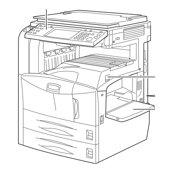
3KH-2 1-1-2 Parts names (1) Main body Figure 1-1-1 Operation panel Document Processor (option) Main power switch Original eject table MP tray Original table TEL connection connector Original width guides Line connection connector 10. Top cover Dual FAX (option) 11. Original placement indicator Line connection connector 12. - Page 17 3KH-2 (2) Operation panel System Menu key Status/Job Cancel key Program key Counter key Send Key Document Box key Accessibility Display key Print indicator Send indicator 10. Receive indicator 11. Memory indicator 12. Error indicator 13. Help key 14. Logout key 15.
-
Page 18: Mechanical Construction
3KH-2 1-1-3 Mechanical construction TOUCH PANEL Dual FAX (option) FCPWB LINPWB NCUPWB IFPWB YC12 FCPWB NCUPWB YC30 SPEAKER YC31 YC25 OPWB-M MPWB YC10 YC10 PSPWB OPWB-L FAX backup kit (option) OPWB-R Figure 1-1-2 The fax system consists of the fax control PWB (FCPWB) and NCU PWB (NCUPWB). 1-1-6... -
Page 19: Installation Environment
3KH-2 1-2 Installation 1-2-1 Installation environment Installation location (Be based on the machine establishment place.) Avoid direct sunlight or bright lighting. Ensure that the photo-conductor will not be exposed to direct sunlight or other strong light when removing paper jams. Avoid extremes of temperature and humidity, abrupt ambient temperature changes, and hot or cold air directed onto the machine. -
Page 20: Unpacking And Installation
3KH-2 1-2-2 Unpacking and installation (1) Unpacking Figure 1-2-1 Unpacking Fax assembly 12. Ferrite cores* Antistatic air-padded bag 13. Air-padded bag* Spacer 14. Terminal seal Modular cord* 15. Alphabet label Installation guide 16. Clamp Operation guide* 17. Approval label* Plastic bag *1: 120 V and Australia/New Zealand Outer case specifications only. - Page 21 3KH-2 Initialization procedure after installing the facsimile system 1. Insert the machine power plug to the wall outlet and turn the main power switch on. 2. Press the status key and enter 10871087 using the numeric keys. The machine enters maintenance mode. 3.
-
Page 22: Installing The Fax Backup Kit (Option)
3KH-2 1-2-3 Installing the fax backup kit (option) Installing the fax backup kit requires the following component: Fax backup kit (P/N 1703KJ0UN0) Press the Power key on the operation panel to off. Make sure that the Power indicator and the Memory indicator are off before turning off the main power switch. -
Page 23: Installing The Dual Fax (Option)
3KH-2 1-2-4 Installing the dual FAX (option) Installing the dual FAX requires the following component: Dual FAX (P/N 120 V: 1503KH2US0, 230 V: 1503KH3EU0, 240 V: 1503KH3AS0) Enter maintenance mode and run maintenance item U019 to check ROM version of the machine if it supports dual FAX. Press the Power key on the operation panel to off. - Page 24 3KH-2 3. Wipe the surface of the TEL connection con- nector with alcohol and adhere the terminal seal. The TEL connection connector on the dual FAX is unavailable (invalid). Seal the termi- nal securely to prevent a user from connect- ing a external telephone.
- Page 25 3KH-2 6. Connect the modular cord that have been removed before installing the dual FAX. 7. Remove the screw from the rear cover. 8. Attach the clamp to the two modular cords and secure it with the screw that have been removed in step 7.
- Page 26 3KH-2 This page is intentionally left blank. 1-2-8...
-
Page 27: Maintenance Mode
1-3 Maintenance Mode 1-3-1 Maintenance mode The machine is equipped with a maintenance function which can be used to maintain and service the machine. (1) Executing a maintenance item Start Press the status key. Enter “10871087” using Maintenance mode is entered. the numeric keys. -
Page 28: Maintenance Mode Item List
3KH-2 (2) Maintenance mode item list Item Section Content of maintenance item Initial setting* Other U000 Outputting an own-status report U019 Displaying the ROM version U600 Initializing all data U601 Initializing permanent data U603 Setting user data 1 U604 Setting user data 2 2 (120 V) 1 (220-240 V) U605... - Page 29 3KH-3 Item Section Content of maintenance item Initial setting* U634 Setting communication control 5 U640 Setting communication time 1 One-shot detection time for remote switching Continuous detection time for remote switching U641 Setting communication time 2 Setting the T0 time-out time Setting the T1 time-out time Setting the T2 time-out time Setting the Ta time-out time...
-
Page 30: Contents Of Maintenance Mode Items
3KH-3 (3) Contents of maintenance mode items Maintenance Description item No. Outputting an own-status report U000 Description Outputs the service status page. Printing a service status page is disabled either when a job is remaining in the buffer or when [Pause All Print Jobs] is pressed to halt printing. -
Page 31: U019 Displaying The Rom Version
3KH-2 Maintenance Description item No. Displaying the ROM version U019 Description Displays the part number of the ROM fitted to each PWB. Purpose To check the part number or to decide, if the newest version of ROM is installed. Method 1. - Page 32 3KH-2 Maintenance Description item No. U600 3. Select [Country Code] and enter a destination code using the numeric keys (refer to the destination (cont.) code list on following for the destination code). 4. Press the start key. There is no operation necessary on this screen. The destination code and the OEM code are displayed with the values currently set.
-
Page 33: U601 Initializing Permanent Data
3KH-2 Maintenance Description item No. Initializing permanent data U601 Description Initializes software switches on the fax control PWB according to the destination and OEM. Purpose To initialize the fax control PWB without changing user registration data. Method 1. Press the start key. 2. -
Page 34: U603 Setting User Data
3KH-2 Maintenance Description item No. Setting user data 1 U603 Description Makes user settings to enable the use of the machine as a fax. Purpose To be run after installation of the facsimile kit if necessary. Method 1. Press the start key. The port that is addressed by U698 is displayed when the optional dual FAX is installed. -
Page 35: U610 Setting System
3KH-2 Maintenance Description item No. Setting system 1 U610 Description Makes settings for fax reception regarding the sizes of the fax paper and received images and automatic print- ing of the protocol list. Start 1. Press the start key. The current setting is displayed in each item. 2. -
Page 36: U611 Setting System
3KH-2 Maintenance Description item No. U610 1. Change the setting using the +/- or numeric keys. (cont.) Description Setting range Initial setting Change in value per step Number of lines to be ignored when receiv- 0 to 22 16 lines ing a fax (A4R, letter) in the auto reduction mode Increase the setting if a page received in the reduction mode is over-reduced and too much trailing... -
Page 37: U612 Setting System
3KH-2 Maintenance Description item No. Setting system 3 U612 Description Makes settings for fax transmission regarding operation and automatic printing of the protocol list. Start 1. Press the start key. 2. Select the item to be set. The screen for the selected item appears. Display Description AUTO REDUCTION... -
Page 38: U620 Setting The Remote Switching Mode
3KH-2 Maintenance Description item No. Setting the remote switching mode U620 Description Sets the signal detection method for remote switching. Be sure to change the setting according to the type of telephone connected to the machine. Method 1. Press the start key. The port that is addressed by U698 is displayed when the optional dual FAX is installed. -
Page 39: Setting The Communication Starting Speed
3KH-2 Maintenance Description item No. U630 2. Select the item to be set. (cont.) Display Description TX SPEED Sets the communication starting speed. RX SPEED Sets the reception speed. TX ECHO Sets the waiting period to prevent echo problems at the sender. RX ECHO Sets the waiting period to prevent echo problems at the receiver. -
Page 40: U631 Setting Communication Control
3KH-2 Maintenance Description item No. Setting communication control 2 U631 Description Makes settings regarding fax transmission. Start 1. Press the start key. 2. Select the item to be set. The screen for the selected item appears. Display Description ECM TX Sets ECM transmission. -
Page 41: U632 Setting Communication Control
3KH-2 Maintenance Description item No. Setting communication control 3 U632 Description Makes settings for fax transmission regarding the communication. Start 1. Press the start key. 2. Select the item to be set. Display Description DIS 4BYTE Sets the DIS signal to 4 bytes. SHORT PROTOCOL TX Sets the short protocol transmission. -
Page 42: U633 Setting Communication Control
3KH-2 Maintenance Description item No. Setting communication control 4 U633 Description Makes settings for fax transmission regarding the communication. Purpose To reduce transmission errors when a low quality line is used. Start 1. Press the start key. 2. Select the item to be set. Display Description V.34... -
Page 43: U640 Setting Communication Time
3KH-2 Maintenance Description item No. Completion U633 Press the stop key. The screen for selecting a maintenance item No. is displayed. (cont.) Setting communication control 5 U634 Description Sets the maximum number of error bytes judged acceptable when receiving a TCF signal. Used as a measure to ease transmission conditions if transmission errors occur. -
Page 44: U641 Setting Communication Time
3KH-2 Maintenance Description item No. Setting communication time 2 U641 Description Sets the time-out time for fax transmission. Purpose To improve transmission performance for international communications mainly. Start 1. Press the start key. The port that is addressed by U698 is displayed when the optional dual FAX is installed. The current setting is displayed in each item. -
Page 45: Setting The T2 Time-Out Time
3KH-2 Maintenance Description item No. Setting the T2 time-out time U641 The T2 time-out time decides the following. (cont.) From CFR signal output to image data reception From image data reception to the next signal reception In ECM, from RNR signal detection to the next signal reception 1. -
Page 46: Setting The Tc Time-Out Time
3KH-2 Maintenance Description item No. Setting the Tc time-out time U641 In the TAD mode, set the time to check if there are any triggers for shifting to fax reception after a connected (cont.) telephone receives a call. Only the telephone function is available if shifting is not made within the set Tc time. In the TAD mode, change the setting when fax reception is unsuccessful or a telephone fails to receive a call. -
Page 47: U650 Setting Modem
3KH-2 Maintenance Description item No. Setting modem 1 U650 Description Sets the G3 cable equalizer. Sets the modem detection level. Start 1. Press the start key. The port that is addressed by U698 is displayed when the optional dual FAX is installed. 2. -
Page 48: U651 Setting Modem
3KH-2 Maintenance Description item No. Setting modem 2 U651 Description Sets the modem output level. Sets the DTMF output level of a push-button dial telephone. Purpose Used if problems occur when sending a signal with a push-button dial telephone. Start 1. -
Page 49: U660 Setting The Ncu
3KH-2 Maintenance Description item No. Setting the NCU U660 Description Makes setting regarding the network control unit (NCU). Purpose To be set when installing the facsimile kit. Start 1. Press the start key. The port that is addressed by U698 is displayed when the optional dual FAX is installed. 2. -
Page 50: Setting The Loop Current Detection Before Dialing
3KH-3 Maintenance Description item No. Setting for a PBX U660 Selects the mode to connect an outside call when connected to a PBX. (cont.) According to the type of the PBX connected, select the mode to connect an outside call. 1. -
Page 51: U671 Clearing The Fax Backup Report Data
3KH-3 Maintenance Description item No. Clearing the FAX backup report data U671 Description Clears the historical record of the fax and Internet-fax job as well as the reserved fax job information which are backed up in the FAX control PWB. Purpose For prevention of backup data leakage. - Page 52 3KH-2 Maintenance Description item No. List of Software Switches of Which the Setting Can Be Changed U699 <System setting> (cont.) Item 21 Declaration of reception size in automatic paper source selection for fax <Communication control procedure> Item 2 Automatic reception level adjustment (V. 17) 1 Automatic reception level adjustment (V.
- Page 53 3KH-2 Maintenance Description item No. List of Software Switches of Which the Setting Can Be Changed U699 (cont.) <Communication time setting> Item 76543210 T3 timeout setting 76543210 T4 timeout setting (automatic equipment) 76543210 T5 timeout setting 76543210 Time before transmission of CNG (1100 Hz) signal 76543210 T0 timeout setting (manual equipment) 7 Phase C timeout in ECM reception 76543210 Timeout 1 in countermeasures against echo...
- Page 54 3KH-2 Maintenance Description item No. Setting the fax backup kit U933 Description Initializes optional fax backup kit (CF) and restore the backup data. Purpose To initialize the CF when call for service (C0700) occurs. Also, to restore data when the hard disk has been damaged.
-
Page 55: User Management
3KH-2 1-3-2 User management In addition to a maintenance function for service, the machine is equipped with a management function which can be oper- ated by users. In this user management mode, settings such as default settings can be changed. (1) Using the user management mode Start Press the System Menu key. -
Page 56: Common Setting
3KH-2 (2) Common setting Changing/Deleting a FAX box Volume adjustment 1. Press [Document Box/Removable Memory], [Reg- Adjust the volume of the speaker and monitor. ister/Edit] of Edit Box and [Register/Edit] of FAX 1. Press [Common Settings], [Next] of Sound and Box. -
Page 57: Fax Setting And Registration
3KH-2 (4) Fax setting and registration 3. Press [OK]. To exit from this setup, press [Close] several times Registering an encryption key until the System Menu default screen is displayed. Note: Up to 20 encryption keys can be registered. 1. Press [FAX/i-FAX], [Next] of TX/RX Common and Selection of telephone line then [Register/Edit] of Encrypt. - Page 58 3KH-3 Selection of Transmit Terminal Identification (TTI) Reception Date/Time The transmit terminal identification (TTI) is the informa- Reception Date/Time function adds the reception date/ tion about the machine (transmit terminal) to be printed time, sender information and number of pages on the top out on FAX on the receiving system.
- Page 59 3KH-2 Rings Operation at the receiving system in encryption com- Change the number of times to let the phone ring before munication answering a call as needed. Note: Sub address communication cannot be used. 1. Press [FAX/i-FAX], [Next] of Reception and then 1.
- Page 60 3KH-2 When [i-FAX] was selected in step 7. Transmission restriction E-mail Address Send or receive originals only when communication requirements are met. 9. Press [OK]. 10. Press [Next] of Forward Setting. Registering Permit FAX No. 11. Press [Change] of Forward Destination. Note: Up to 50 Permit FAX numbers can be registered.
-
Page 61: Date And Timer
3KH-3 Setting reception restriction 2. Press [Off] (not to print), [On] (to print), or [Error Restrict incoming faxes so that you only receive originals and Forward Only]. from senders registered in Permit FAX No. and Permit ID 3. Press [OK]. No. -
Page 62: One-Touch Keys
3KH-3 15. Press [Encrypted Transmission]. When you do not 1. Press [Edit Destination], [Register/Edit] of Address use encryption, go to step 20. Book, [Add], [Group], and then [Next]. 16. Press [On] and select Encryption Key No. 2. Press [Change] of Address Number. 17. -
Page 63: Job Accounting
3KH-3 beros(Win2000/2003)] as the authentication 4. Enter the account name (up to 32 characters) and method. press [OK]. 4. Press [OK]. 5. Enter the account ID (eight digits) following 3 and 4. Setting range: 0 to 99999999 Adding a user 6. - Page 64 3KH-3 Count: Number of pages copied, printed, faxed, and the total number of those pages are displayed. When Total is selected for Managing the Copy/ Print Count: Number of pages printed (by copier and printer), number of pages faxed, and the total number of those pages are displayed.
-
Page 65: Error Codes
1-4 Error Codes 1-4-1 Error codes (1) Error code Error codes are listed on the communication reports, activity report, etc. The codes consist of an error code indication U followed by a 5-digit number. (Error codes for V34 communication errors start with an E indication, followed by five digits.) The upper three of the five digits indicate general classification of the error and its cause, while the lower two indicate the detailed classification. -
Page 66: Table Of General Classification
(2) Table of general classification Error code Description U00000 No response or busy after the set number of redials. U00100 Transmission was interrupted by a press of the stop/clear key. U00200 Reception was interrupted by a press of the stop/clear key. U00300 Recording paper on the destination unit has run out during transmission. - Page 67 Error code Description U03400 Polling reception was interrupted because of a mismatch in individual numbers (destination unit is either of our make or by another manufacturer). U03500 In confidential polling reception, the specified confidential box No. was not registered in the desti- nation.
-
Page 68: U004Xx Error Code Table: Interrupted Phase B
(2-1) U004XX error code table: Interrupted phase B Error code Description U00420 A relay request was received from the host center but interrupted because of a mismatch in permit ID or telephone number. U00421 Subaddress-based relay reception was interrupted because of a mismatch in the specified subad- dress relay box number. -
Page 69: U006Xx Error Code Table: Problems With The Unit
(2-2) U006XX error code table: Problems with the unit Error code Description U00600 The document processor cover is open. U00601 Document jam or the document length exceeds the maximum. U00602 Image scanning section problem. U00603 No document feed. U00604 Document length exceeded the limit of the bitmap memory capacity. U00610 Recording section cover is open. -
Page 70: U010Xx Error Code Table: G3 Transmission
(2-5) U010XX error code table: G3 transmission Error code Description U01000 An FTT signal was received for a set number of times after TCF signal transmission at 2400 bps. Or, an RTN signal was received in response to a Q signal (excluding EOP) after transmission at 2400 bps. - Page 71 Error code Description U01043 A DCN signal was received after transmission of an NSS1, NSS2 (TCF) signal (between units of our make). U01044 A DCN signal was received after transmission of an NSS3, TCF signal (between units of our make). U01045 A DCN or other inappropriate signal was received after transmission of an MPS signal.
-
Page 72: U011Xx Error Code Table: G3 Reception
(2-6) U011XX error code table: G3 reception Error code Description U01100 Function of the unit differs from that indicated by a DCS signal. U01101 Function of the unit (excl. communication mode select) differs from that indicated by an NSS sig- nal. - Page 73 Error code Description U01154 A DCN signal was received after transmission of an RNR signal (ECM). U01155 A DCN signal was received after transmission of an SPA signal (short protocol). U01160 During message reception, transmission time exceeded the maximum transmission time per line. U01161 Number of error lines exceeded limits during message reception.
-
Page 74: U017Xx Error Code Table: V.34 Transmission
(2-7) U017XX error code table: V.34 transmission Error code Description U01700 A communication error occurred in phase 2 (line probing). U01720 A communication error occurred in phase 4 (modem parameter exchange). U01721 Operation was interrupted due to the absence of a common communication speed between units. U01700: A communication error that occurs at the transmitting unit in the period after transmission of INFO0 before enter- ing phase 3 (primary channel equivalent device training). -
Page 75: Self-Diagnosis
3KH-2 1-5 Troubleshooting 1-5-1 Self-diagnosis (1) Self-diagnostic function This unit is equipped with a self-diagnostic function. When a problem is detected, printing is disabled and the problem dis- played as a code consisting of C followed by a number, indicating the nature of the problem. A message is also displayed requesting the user to call for service. - Page 76 This page is intentionally left blank. 1-5-2...
-
Page 77: Upgrading The Firmware On The Fax Control Pwb
3KH-2 1-6 Requirements on PWB Replacement 1-6-1 Upgrading the firmware on the fax control PWB Firmware upgrading requires the following tools: Compact Flash (Products manufactured by SANDISK are recommended.) or USB memory NOTE When writing data to a new Compact Flash from a computer, be sure to format it in advance. Procedure 1. - Page 78 This page is intentionally left blank. 1-6-2...
-
Page 79: Electrical Parts Layout
3KH-2 2-1 Electrical Parts Layout 2-1-1 Electrical parts layout Figure 2-1-1 Fax control PWB (FCPWB)......Modulates, demodulates, compresses, decompresses and smoothes out image data, and converts resolution of image data. NCU PWB (NCUPWB)......... Controls connection to the telephone line. Fax backup kit (option)......... Stores the internet FAX reception data, FAX box data and job accounting data for backup. - Page 80 This page is intentionally left blank. 2-1-2...
- Page 81 2-2 Operation of the PWBs 2-2-1 Fax control PWB FCPWB SDRAM (Upper/Lower) 32MBx128Mbitx2 32bit Data bus RESETn (U11) Address bus ASIC 200MHz READY (U21) Machine RESETn Main TELSEL RESET IC MDMRESn EARTH (U73) (via interface 16bit DCCONT PWB) +5.0V CPUCLK +3.3V Speaker MODEM...
- Page 82 Figure 2-2-2 Fax control PWB silk-screen diagram 2-2-2...
- Page 83 Connector Pin No. Signal Voltage Description Not used Connected Not used to the AUDIO 3.3 V DC Speaker control signal machine +3.3 V 3.3 V DC 3.3 V DC supply main PWB Ground (via inter- face PWB) Not used 3.3 V DC Address bus A11 3.3 V DC Address bus A9...
- Page 84 Connector Pin No. Signal Voltage Description TXDMACKn 5 V DC DMACK transmission signal Connected 5 V DC Data signal D14 to the 5 V DC Data signal D13 machine 5 V DC Data signal D11 main PWB 5 V DC Data signal D9 (via inter- face PWB)
- Page 85 2-2-2 NCU PWB FCPWB Accounting Surge LINE1 Noise pulse Noise absorption Line fileter elimination fileter section (modular circuit LINE2 circuit circuit V10, V12 connector) C038, C039 C041, C042 C043 Ground start EARTH circuit DB20, PC20 TELOFHKn External telephone off-hook detection circuit Relay TEL SEL...
- Page 86 Connector Pin No. Signal Voltage Description LINE1 Line signal Connected LINE1 Line signal to the fax Not used control Not used PWB. Not used Ground Ground Ground Ground Ground Ground +5VDC 5 V DC 5 V DC supply +5VDC 5 V DC 5 V DC supply +5VDC 5 V DC...