Table of Contents
Advertisement
Quick Links
See also:
User Manual
Service
This manual is to be used by qualified appliance
technicians only. Maytag does not assume any
responsibility for property damage or personal
injury for improper service procedures done by
an unqualified person.
Electric
Slide-In
Range
This Base Manual covers general information
Refer to individual Technical Sheet
for information on specific models
This manual includes, but is
not limited to the following:
JES8750AAB/W
JES8850AAB/Q/S/W
JES8850ACB/S/W
JES9750AAB/S/W
JES9750ACB/W
JES9800AAB/Q/S/W
JES9800ACB/S/W
JES9860AAB/S/W
JES9860ACB/S/W
16025927
February 2005
©2005 Maytag Services
Advertisement
Table of Contents

Related Manuals for Jenn-Air JES8750AAB


Summary of Contents for Jenn-Air JES8750AAB
- Page 1 Refer to individual Technical Sheet injury for improper service procedures done by an unqualified person. for information on specific models This manual includes, but is not limited to the following: Electric JES8750AAB/W Slide-In JES8850AAB/Q/S/W JES8850ACB/S/W JES9750AAB/S/W Range JES9750ACB/W JES9800AAB/Q/S/W...
-
Page 2: Important Information
Important Information Pride and workmanship go into every product to provide our customers with quality products. It is possible, however, that during its lifetime a product may require service. Products should be serviced only by a qualified service technician who is familiar with the safety procedures required in the repair and who is equipped with the proper tools, parts, testing instruments and the appropriate service information. -
Page 3: Table Of Contents
Table of Contents Important Information ........... 2 Quick Test Mode ............ 18 Important Safety Information Description of Fault Codes ........19 All Appliances ............4 Disassembly Procedures Surface Cooking Units ..........4 Moving and Replacing Range ........ 20 Ovens ............... 5 Cartridge Assembly (Select Models) ...... -
Page 4: Important Safety Information
Important Safety Information ALL APPLIANCES WARNING 1. Proper Installation—Be sure your appliance is properly installed and grounded by a qualified To reduce the risk of the appliance tipping, it must be technician. secured by a properly installed anti-tip bracket(s). To make sure bracket has been installed properly, remove 2. -
Page 5: Ovens
Important Safety Information OVENS In Case of Fire 1. Use Care When Opening Door—Let hot air or steam Fires can occur as a result of over cooking or excessive escape before removing or replacing food. grease. Though a fire is unlikely, if one occurs, proceed as follows: 2. -
Page 6: Product Safety Devices
Important Safety Information Product Safety Devices Safety devices and features have been engineered into the product to protect consumer and servicer. Safety devices must never be removed, bypassed, or altered in such a manner as to defeat the purpose for which they were intended. -
Page 7: General Information
Brushed Chrome Amana Traditional White Magic Chef Traditional Almond Graffer & Prostyle Sattler Monochromatic Bisque Hardwick Stainless Jenn-Air Traditional Bisque Maytag W White on White Norge Frost White (True Color White) Universal Natural Bisque (True Color Bisque) Crosley Listing Fuel... -
Page 8: Specifications
To request service information or replacement parts, the If registration card is missing: service center will require the complete model, serial, and • For Jenn-Air product call 1-800-536-6247 or visit the manufacturing number of your slide-in range. The Web Site at www.jennair.com number can be found on the oven chassis behind the •... -
Page 9: Range Description
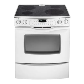
Range Description Range Description Cooking Surface Downdraft Vent Infinite Switches Electronic Controls Oven Cavity: Broil Element Bake Element Convection Fan Baking Racks Temperature Probe Access Panel: Model Number Rating Label 16025927 ©2005 Maytag Services... -
Page 10: Troubleshooting Procedures
Troubleshooting Procedures WARNING To avoid risk of electrical shock, personal injury, or death, disconnect power to oven before servicing, unless testing requires power. Troubleshooting Chart Problem Possible Cause Correction • Check element for continuity, Open bake element ........replace if failed. Loose wire connection or broken wire.. -
Page 11: Fault Code Chart
Troubleshooting Procedures WARNING To avoid risk of electrical shock, personal injury, or death, disconnect power to oven before servicing, unless testing requires power. Problem Possible Cause Correction • Turn off circuit breaker for five minutes Programming error ........Self-clean cycle not and try oven again. -
Page 12: Component Testing Procedures
Troubleshooting Procedures WARNING To avoid risk of electrical shock, personal injury, or death, disconnect power to oven before servicing, unless testing requires power. Oven Sensor and Meat Probe Charts MEAT PROBE OVEN SENSOR Type: NTC Thermistor Sensor Type: RTD 1000Ω platinum Calibration: 9938Ω... - Page 13 Component Testing Procedures WARNING To avoid risk of electrical shock, personal injury or death; disconnect power to oven before servicing, unless testing requires power. Component Testing Procedures Illustration Component Test Procedure Results Oven light housing Disconnect connector and test Verify bulb is plugged in properly. All models resistance of terminals ......
- Page 14 Testing Procedures WARNING To avoid risk of electrical shock, personal injury or death; disconnect power to oven before servicing, unless testing requires power. Illustration Component Test Procedure Results Measure resistance ......Approx. 1100 Ω at room temperature Temperature sensor All models 75°...
-
Page 15: Oven Control Testing Procedures
Testing Procedures WARNING To avoid risk of electrical shock, personal injury or death; disconnect power to oven before servicing, unless testing requires power. Oven Control Testing Procedures Changing factory set default options: 1. Press Setup Options and the desired pad simultaneously (see table). 2. - Page 16 Testing Procedures WARNING To avoid risk of electrical shock, personal injury or death; disconnect power to oven before servicing, unless testing requires power. Component Test Procedure Results Control Panel Assembly Closed circuitry resistance Trace Measurement 7 & 8 Continuity (defined as continuity): 1350 –...
-
Page 17: Relay Logic
Testing Procedures WARNING To avoid risk of electrical shock, personal injury or death; disconnect power to oven before servicing, unless testing requires power. Relay Logic NOTE: Subsequent changes implemented after the release of this technical sheet may have altered the parameters identified in this chart. -
Page 18: Quick Test Mode
Testing Procedures WARNING To avoid risk of electrical shock, personal injury or death; disconnect power to oven before servicing, unless testing requires power. "Quick Test" Mode for Electronic Oven Control (EOC) II Follow the procedure below to perform the EOC II quick test. Instructions must be entered within 16 seconds of each other (via the touch pad) or the EOC will exit the test mode. -
Page 19: Error Codes
Testing Procedures WARNING To avoid risk of electrical shock, personal injury or death; disconnect power to oven before servicing, unless testing requires power. Description of Fault Codes Each Fault Code consists of an "F" followed by a number, dash and a number or letter. The following table describes each Fault Code and the component to troubleshoot. -
Page 20: Disassembly Procedures
Disassembly Procedures To avoid risk of electrical shock, personal injury or death; disconnect power to unit before servicing. Removing and Replacing Range 8. Remove screws securing element mounting brackets to main top assembly (select models). 1. Remove power from unit. 9. -
Page 21: Bottom Access Panel
Disassembly Procedures To avoid risk of electrical shock, personal injury or death; disconnect power to unit before servicing. Transformer Bottom Access Panel 1. Remove power from unit. 1. Grasp top of bottom access panel and gently pull 2. Remove back panel, see "Back Panel" procedure. down and out. -
Page 22: Oven Sensor
Disassembly Procedures To avoid risk of electrical shock, personal injury or death; disconnect power to unit before servicing. NOTE: Reposition fiberglass insulation around light Oven Sensor socket to eliminate the possibility of any heat 1. Remove power from unit. related problems. 2. -
Page 23: Oven Door Latch
Disassembly Procedures To avoid risk of electrical shock, personal injury or death; disconnect power to unit before servicing. Door Oven Door Hinge Latch 1. Remove power from unit. 2. Remove unit from installation position, see “Removing and Replacing Range” procedure. Hi-Limit 3. - Page 24 Disassembly Procedures To avoid risk of electrical shock, personal injury or death; disconnect power to unit before servicing. NOTE: Proceed with the following steps for inner door disassembly. 10.Remove screws securing lower door glass retainer to door baffle and remove. 11 Slide inner door glass downward to release from upper door glass retainers and remove.
- Page 25 Appendix A 16025927 A – 1 ©2005 Maytag Services...
-
Page 26: Appendix A: Installation Instructions
Installation Instructions (Models JES8750AA*, JES8850A**) IMPORTANT PLEASE KEEP FOR THE USE OF THE LOCAL ELECTRICAL INSPECTOR. FIGURE 1 NOTE: Figure may not be representative of actual unit. The 30 inches (76.2 cm) minimum clearance between the installing a range hood that projects horizontally a top of the cooking surface and the bottom of an minimum of 5 inches (13 cm) beyond the bottom of the unprotected wood or metal cabinet can be reduced to 24... -
Page 27: Models Jes8750Aa*, Jes8850A
Installation Instructions (Models JES8750AA*, JES8850A**) FIGURE 2 FIGURE 3 Notes: 1. Provide for either a 3-wire or 4-wire 120/208, 120/240 volt outlet per applicable cord in shaded area shown. Refer to installation instructions for proper positioning of outlet. 2. Dimension K (figure 4, page 4) is from the wall to the side edge of the oven door. It does not include the curvature of the glass or the depth of the handle. - Page 28 Installation Instructions (Models JES8750AA*, JES8850A**) MOBILE HOMES LOCATING THE RANGE Place range in a well lit area. Do not set range over holes The installation of a range designed for mobile home in the floor or other locations where it may be subject to installation must conform with the Manufactured Home Construction and Safety Standard, Title 24 CFR, Part strong drafts.
- Page 29 STEP 3 - Range Installation A. Wood Construction: A. A Jenn-Air range may be installed by one person. 1. Floor: Locate the center of the two holes identified in B. Align the range to its designated location and slide it figure 5 as “HOLES FOR FLOOR.”...
- Page 30 Installation Instructions (Models JES8750AA*, JES8850A**) CONNECTING THE RANGE ELECTRIC SUPPLY RANGE CONNECTIONS Some models are shipped direct from the factory with The range must be installed in accordance with Local and National Electric Code (NEC) ANSI/NFPA No. 70-latest service cords (pigtails) attached. There are no range connections necessary on these models.
- Page 31 Installation Instructions (Models JES8750AA*, JES8850A**) 3-WIRE SERVICE CORD OR CONDUIT 4-WIRE SERVICE CORD OR CONDUIT INSTALLATION INSTALLATION (MOBILE HOMES OR AS REQUIRED BY CODES) 1. Insure that the copper ground strap IS CONNECTED between the middle post of the main terminal 1.
- Page 32 Installation Instructions (Models JES9750A**, JES9800A**, JES9860A**) IMPORTANT PLEASE KEEP FOR THE USE OF THE LOCAL ELECTRICAL INSPECTOR. FIGURE 1 NOTE: Figure may not be representative of actual unit. The 30 inches (76.2 cm) minimum clearance between the installing a range hood that projects horizontally a top of the cooking surface and the bottom of an minimum of 5 inches (13 cm) beyond the bottom of the unprotected wood or metal cabinet can be reduced to 24...
- Page 33 Installation Instructions (Models JES9750A**, JES9800A**, JES9860A**) FIGURE 2 FIGURE 3 Notes: 1. Provide for either a 3-wire or 4-wire 120/208, 120/240 volt outlet per applicable cord in shaded area shown. Refer to installation instructions for proper positioning of outlet. 2. Dimension K (figure 4, page 4) is from the wall to the side edge of the oven door. It does not include the curvature of the glass or the depth of the handle.
- Page 34 Installation Instructions (Models JES9750A**, JES9800A**, JES9860A**) MOBILE HOMES LOCATING THE RANGE The installation of a range designed for mobile home Place range in a well lit area. Do not set range over holes in the floor or other locations where it may be subject to installation must conform with the Manufactured Home Construction and Safety Standard, Title 24 CFR, Part strong drafts.
- Page 35 Options STEP 3 - Range Installation A. Wood Construction: A. A Jenn-Air range may be installed by one person. 1. Floor: Locate the center of the two holes identified in figure 5 as “HOLES FOR FLOOR.” Drill a 1/8 B. Align the range to its designated location and slide it (3 mm) pilot hole in the center of each hole (a nail back into position.
- Page 36 Installation Instructions (Models JES9750A**, JES9800A**, JES9860A**) CONNECTING THE RANGE ELECTRIC SUPPLY RANGE CONNECTIONS Some models are shipped direct from the factory with The range must be installed in accordance with Local and service cords (pigtails) attached. There are no range National Electric Code (NEC) ANSI/NFPA No.
- Page 37 Installation Instructions (Models JES9750A**, JES9800A**, JES9860A**) 3-WIRE SERVICE CORD OR CONDUIT 4-WIRE SERVICE CORD OR CONDUIT INSTALLATION INSTALLATION (MOBILE HOMES OR AS REQUIRED BY CODES) 1. Insure that the copper ground strap IS CONNECTED between the middle post of the main terminal 1.
- Page 38 Installation Instructions (Models JES9750A**, JES9800A**, JES9860A**) DOWNDRAFT INSTALLATION INSTRUCTIONS S Determine where you will be locating the electrical outlet. It must be in the floor or on the wall within the area shown in figure 2 or 3. S Determine how you will be venting your downdraft blower.
- Page 39 Installation Instructions (Models JES9750A**, JES9800A**, JES9860A**) 3. Make cutout in the cabinet floor of either the right or left side cabinet as shown in figures 14 or 15. 4. Relocate the mounting brackets on the blower housing as shown in figure 17. NOTE: The mounting br ackets shown in figure 16 are as assembled at the factory for floor or...
-
Page 40: Range Installation
Installation Instructions (Models JES9750A**, JES9800A**, JES9860A**) 8. Install the 6 (15.24 cm) elbow of the blower housing INSTALLING THE BLOWER and secure with duct tape. The open end of the elbow NOTE: Install the blower prior to installing the should be pointed to the left. Attach the 6 (15.24 cm) range. - Page 41 Appendix B 16025927 B – 1 ©2005 Maytag Services...
- Page 42 Use Information (Models JES8750AA*, JES8850A**) OvENCOOKING Keep Clock Warm _y o_ Oven Light Bread Timer 2 Theelectroniccontrolisdesigned foreaseinprogramming. Thedisplay w indowonthecontrolshowstimeofday,timerandovenfunctions. ControlpanelshownincludesConvectandothermodelspecificfeatures.(Stylingmayvarydepending onmodel.) NOT : E Thetemperatureortimewillbe Clocktimecannotbechangedwhenthe CAUTION: automaticallyenteredfoursecondsafter ovenhasbeenprogrammed forclockcon- , Besureallpackingmaterialisre- se ection, trolledcooking,self-clean o r delayedself- movedfromovenbeforeturningon.
- Page 43 Use Information (Models JES8750AA*, JES8850A**) ]O EN C OOKING, coN J 5.Attheendofthesettime,"END"willbe BAKE PAD CONVECT BAKE PAD/ displayedandtwo chimeswill sound Useforbakingandroasting. CONVECT ROAST PAD we y f llo db twochim sev ry30s ( E E S L CT M DELS) ondsforuptofiveminutes.Pressthe I.PressBakepad.
- Page 44 Use Information (Models JES8750AA*, JES8850A**) w ll ress top Time padagain BROIL PAD 4 Attheend fco ktime,theoven i Usefortopbrowningorbroiling.Forbest shutoffautomatically, "End"andCOOK TIME must beflashingto setthe results,usethebroilerpanpr videdwith TIMEw llbedisplayed andthreech mes delaystart time. 5.Presstheappropriatenumberpadsto yourrange, willsound. I. PresstheBroilpad. .Press ance pad.Removefoodfrom enterthetimeyouwanttheovento oven.
- Page 45 Use Information (Models JES8750AA*, JES8850A**) KI G OO N rCONT. KEEP WA M PAD (SELECT R AD P ROO I F NG QuickProofingpr vides fasterresultsthan proofing without countertop orstandard M DELS) ( ELE T M DELS) harmin theyeast. Forsafelykeep n oods armor or arm i gf F rproofin orallo n yeastbrea prod- ng readsandp ates,...
-
Page 46: Models Jes9750A**, Jes9860A
Use Information (Models JES9750A**, JES9860A**) OOKING IMER ONTROL PTIONS ETTING ONTROL UNCTIONS ONTROL PERATION LOCK B – 6 16025927 ©2005 Maytag Services... - Page 47 Use Information (Models JES9750A**, JES9860A**) ONVECT ONVECT OAST SELECT MODELS ANCEL NOTES: 16025927 B – 7 ©2005 Maytag Services...
- Page 48 Use Information (Models JES9750A**, JES9860A**) OOKING CONT ROIL UICK REHEAT SELECT MODELS LOCK ONTROLLED OOKING NOTES: B – 8 16025927 ©2005 Maytag Services...
- Page 49 Use Information (Models JES9750A**, JES9860A**) SELECT READ ROOFING MODELS SELECT MODELS NOTES: ROBE SELECT MODELS 16025927 B – 9 ©2005 Maytag Services...
- Page 50 Use Information (Models JES9750A**, JES9860A**) OOKING CONT RYING NOTES: B – 10 16025927 ©2005 Maytag Services...
-
Page 51: Model Jes9800A
Use Information (Model JES9800A**) OVEN COOKING Drying Timer Timer J-ig[It Bread ......f4o_Tir_Bee_ TPmt; C/_ La,,guage Det_ult Set,, Theelectroniccontrolisdesignedforeaseinprogramming.Thedisplaywindowonthecontrolshowstimeofday,timerandovenfunctions. CAUTION: N T : Thetemperatureortimewillbe Clocktime cannot bechangedwhenthe automaticallyenteredfour secondsafter ovenhasbeenprogrammedforclockcon- " Besure all packingmaterial isre- selection, trolled cooking,self-cleanor delayedself- movedfromovenbeforeturningon. Ifmore than30secondselapsebetween clean. - Page 52 Use Information (Model JES9800A**) 5.Attheendofthesettime,"END"willbe B KE 5.Whencookingiscomplete,press a1 displayedandtwo chimeswill sound Useforbakingand tel pad Remo efoodfromo en roast ng followedbyonechimeevery30seconds foruptofiveminutes.P essthecorre- I.PressBakepad. CONVECT BAKE PAD/ spon in d gT m r padtocancelthe 2. ressaga nfor35 °Forpressthe uto CONVECT ROAST PAD chimes.
- Page 53 Use Information (Model JES9800A**) OV N COOKING, CONT. BROIL PAD 4.Attheendofcooktime,theovenwil{ Press Stop i e padaga n TOI i .S Usefortopbrowningorbroi ing.Forbest shutoffautomatica y,"End"andCOOK TIME must b fl e ash g o se h, in t results,usethebroilerpanprovidedwith T MEwillbedisplayed andthreechimes delays ar t me, t t i yourrange,...
-
Page 54: Care And Cleaning
Care and Cleaning LEANING ROCEDURES – P LOCK AND ONTROL ANDLE LASTIC INISHES ONTROL ANEL CCESS ANEL & D – INDOW LASS ONTROL NOBS PRONGS PRONGS GREASE NTERIORS NAMEL ACKS ROILER AN AND NSERT B – 14 16025927 ©2005 Maytag Services... - Page 55 Care and Cleaning & C LEANING CONT – C TAINLESS TEEL RATES AST ALUMINUM COATED WITH NON STICK SELECT MODELS FINISH – RILL CCESSORIES – ASIN AND ASIN ORCELAIN REASE – P TORAGE RAWER AINTED NAMEL 16025927 B – 15 ©2005 Maytag Services...