Table of Contents
Advertisement
Instruction Manual
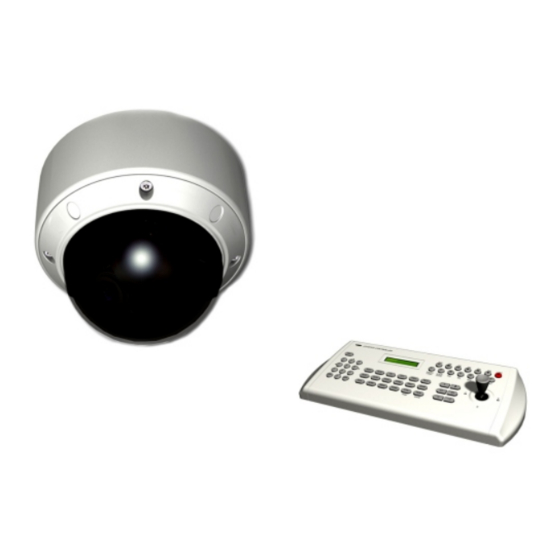
Minitrax Dome Camera
PTZ
Surface mount
MANUAL LABEL
50201270
Please read this manual thoroughly before use, and keep it handy for future reference.
105(+/-5)mm
M6/05/30
M5/09/12 M6/05/30
M6/05/30
VANDAL RESISTANT
COLOR DOME CAMERA
Keyboard Controller
(not supplied)
PRODUCTION RELEASE & REVISION
REV
DWG No
DESCRIPT'N/BUYER
A
INITIAL
-------------------- 50301804 S.A.PARK N.C.PARK 10-11-M5
C
-------------------- 50301804 S.A.PARK N.C.PARK 05-30-M6
BUYER BRAND TYPE
MODEL No.
BRAND
ADDRESS
81mm
ex) HITRON TYPE
Model No.: HCV-851PZ0S4
AC/CA 24V ~ 50Hz 10W
DC 12V
10W
HITRON SYSTEMS INC.
109-19 MAJEON-RI, SAMJUK-MYEON,
ANSUNG-CITY, KYUNGKI-DO, 456-881 KOREA
NOTES
1.MODEL: HCV-851PZ0S4, HCV-651PZ0S4 / ALL BRAND
BIND
: STAPLES-2
3.FINISH: -------------------
4.COLOR: TEXT-BLACK
5.SIZE: 105(+/-5)mm x 148(+/-5)mm R: 0.0
6.ANY CHANGE OR ALTERNATION MUST BE
APPROVED BY HITRON ENGINEERING.
50301804
APPROVALS
UNLESS OTHERWISE SPECIFIED
ALL DIMENSIONS ARE IN MM.
- TOLERANCE
LABEL
+/- 1.5
MANUAL
+/- 3.5
N.C.PARK
ANGULAR +/- 0.5
MATERIAL
CHKED
2
FINISH
DRAWN
S.A.PARK 05.30.M6
PARTS No. BY
DATE
CHK
POWER
ITEM
DESCRIPTION/MATERIAL
QTY
PARTS LIST
DATE
TITLE
05.30.M6
MANUAL INSTRUCTION
SIZE
DWG No
REV.
A4
----------------------------
P/ N
SCALE
DO NOT SCALE
A
Advertisement
Table of Contents

Related Manuals for Hitron Minitrax HCV-851PZ0S4


Summary of Contents for Hitron Minitrax HCV-851PZ0S4
- Page 1 109-19 MAJEON-RI, SAMJUK-MYEON, ANSUNG-CITY, KYUNGKI-DO, 456-881 KOREA Keyboard Controller (not supplied) NOTES MANUAL LABEL 1.MODEL: HCV-851PZ0S4, HCV-651PZ0S4 / ALL BRAND 50201270 BIND : STAPLES-2 3.FINISH: ------------------- Please read this manual thoroughly before use, and keep it handy for future reference.
-
Page 2: Instruction Manual
Instruction Manual Minitrax Dome Camera VANDAL RESISTANT COLOR DOME CAMERA Surface mount Keyboard Controller (not supplied) Please read this manual thoroughly before use, and keep it handy for future reference. -
Page 3: Warnings And Cautions
WARNINGS AND CAUTIONS: TO REDUCE THE RISK OF FIRE OR ELECTRIC SHOCK, DO NOT EXPOSE THIS PRODUCT TO RAIN OR MOISTURE. DO NOT INSERT ANY METALLIC OBJECTS THROUGH THE VENTILATION GRILLS OR OTHER OPENINGS ON THE EQUIPMENT . CAUTION: CAUTION CAUTION RISK OF ELECTRIC SHOCK DO NOT OPEN... -
Page 4: Fcc Compliance Statement
FCC COMPLIANCE STATEMENT FCC INFORMATION : THIS EQUIPMENT HAS BEEN TESTED AND FOUND TO COMPLY WITH THE LIMITS FOR A CLASS A DIGITAL DEVICE, PURSUANT TO PART 15 OF THE FCC RULES. THESE LIMITS ARE DESIGNED TO PROVIDE REASONABLE PROTECTION AGAINST HARMFUL INTERFERENCE WHEN THE EQUIPMENT IS OPERATED IN A COMMERCIAL ENVIRONMENT. -
Page 5: Important Safeguards
IMPORTANT SAFEGUARDS Read these instructions. Keep these instructions. Heed all warnings. Follow all instructions. Do not use this apparatus near water. Clean only with dry cloth. Do not block any ventilation openings. Install in accordance with the manufacturer's instructions. Do not install near any heat sources such as radiators, heat registers, stoves, or other apparatus (including amplifiers) that product heat.. -
Page 6: Table Of Contents
TABLE OF CONTENTS Chapter 1. INTRODUCTION 1.1 Features Operation Requirements Chapter 2. INSTALLATION AND CONFIGURATION 2.1 Package Contents 2.2 Base Installation 2.3 Heater kit Installation (option) 2.4 Basic Configuration PTZ Dome Camera System 2.5 Setting Protocol of Dome Camera 2.6 Setting Address (ID) of Dome Camera 2.7 Connecting Wiring Chapter 3. -
Page 7: Chapter 1. Introduction
Chapter 1. Introduction 1.1 Features The PTZ Dome keyboard controller and the PTZ Dome camera make up the building blocks for any surveillance/security system. Using multiple keyboard controllers and multiple dome cameras, no place is too large for monitoring. Extensible and flexible architecture facilitates remote control functions for a variety of external switching devices such as multiplexers and DVRs. -
Page 8: Operation Requirements
1.2 Operation Requirements Alarm Input <Sensor> RS-485 J-box MULTIPLEXER PTZ DOME PTZ DOME PTZ DOME RS-485 KEYBOARD MONITOR RS-485 VIDEO Typical System Configuration... -
Page 9: Chapter 2. Installation And Configuration
Chapter 2. Installation and Configuration 2.1 Package Contents The package contains the following. PTZ Dome (Dome Camera) Instruction Manual (This Document) Modular Cable Interface Board Accessory Kit for Installing PTZ Dome Template Sheet 2.2 Base Installation Connect power and communication lines to the dome base board. (See Figure 1) Fit the hole grommet on the cable and attach the gasket to the housing. - Page 10 2.2 Base Installation, continued BNC Jack COLOR DESCRIPTION BLACK 485 (+) Camera Output BROWN 485 ( ) AC24V / DC12V ORANGE AC24V / DC12V BLUE ALARM COMMON BOTTOM VIOLET ALARM IN Figure 1 Connection Cable Description Address(ID) / Protocol Selection Switches RS-485 Termination S/W Terminated Not terminated...
- Page 11 2.2 Base Installation, continued Torx screws M5x10 (4x) Torx screws Seal around M5x10 (4x) the housing base tightly using the silicon rubber Figure 4 Figure 6 CEILING Template Sheet Plastic Anchor (4x) Figure 5 Rubber Washers(4x) Mounting Screw M6x35 (4x) MOUNTING HOUSING ELECTRICAL TO THE ELECTRICAL BOX...
-
Page 12: Heater Kit Installation (Option)
2.3 Heater kit Installation (option) 1. Place the Heater element in slot "A". Please ensure that the cables are facing upwards and the heater is pointing towards the Dome. 2. Place the PCB in slot "B". Please ensure that the PCB is facing away from the Dome with the connection blocks at the top. -
Page 13: Basic Configuration Ptz Dome Camera System
2.4 Basic Configuration PTZ Dome Camera System Alarm Input <Sensor> PTZ DOME MONITOR J-BOX BACK J-BOX FRONT DOME1 DOME1 DOME2 DOME2 SLAVE KBD SLAVE KBD DC 12V DC 12V ALARM/PC ALARM/PC DATA2 DATA2 DATA1 DATA1 VIDEO VIDEO IN IN RS-232C RS-232C DATA1 DATA2... -
Page 14: Setting Protocol Of Dome Camera
2.5 Setting Protocol of Dome Camera If a dome camera is to be installed with a PTZ Dome keyboard controller, select F2 protocol. Consult service personnel if a dome camera is installed with device other than a keyboard controller. S/W - No. FUNCTION NTSC NTSC/PAL... -
Page 15: Setting Address (Id) Of Dome Camera
2.6 Setting Address (ID) of Dome Camera To prevent wrong operation and malfunction, each dome camera must have a unique address (ID). When installing multiple dome cameras using a multiplexer, it is suggested that the dome camera address match the multiplexer port number. Example : Port 1 = Dome 1, Port 2 = Dome 2, .. -
Page 16: Connecting Wiring
2.7 Connecting Wiring 2.7-1 Connecting to the RS-485 (baud rate 9600bps.) The dome camera can be controlled remotely by an external device or control system, such as a control keyboard, using RS-485 half-duplex. Connect Marked Rx+, Rx- to Tx+ and Tx- of the RS-485 control system. 2.7-2 Connecting Video out connector (if RS-485 connecting) -
Page 17: Chapter 3. Program And Operation
Chapter 3. Program and Operation Notice Below symbols mean some action of joystick controller. : move joystick up and down direction. : move joystick left and right direction. : twist joystick. : push defined key. 3.1 Main Menu MAIN MENU PRESET TOUR AUTO SCAN... -
Page 18: Preset Menu
3.2 Preset Menu PRESET MENU NUMBER: 01 TITLE: ------------- 0/1234567890 1/1234567890 2/1234567890 3/1234567890 4/1234567890 5/1234567890 SAVE & EXIT EXIT : move cursor up and down. : move cursor left and right or select or change values. : move dome camera to saved preset point at NUMBER:xx, or character at : exit current menu without data saving. - Page 19 3.2 Preset Menu, continued 3.2-3 Run Preset Press preset number key and press PRST key. For example, if you want to go to number 3 preset point. Press 3 key and press PRST key. If you are in menu mode, this is invalid.
-
Page 20: Tour Menu
3.3 Tour Menu TOUR MENU TOUR : 1 TITLE: ------------- DWELL TIME: 05 SEC -- -- -- -- -- -- -- -- -- -- -- -- -- -- -- -- DELETE DATA SAVE & EXIT EXIT : move cursor up and down. : move cursor left and right or select or change values. -
Page 21: Auto Scan Menu
3.4 Auto Scan Menu AUTO SCAN MENU SCAN: 1 TITLE: -------------- START POINT : 000.00 TILT & ZOOM: 000.00 POINT: 000.00 SAVE & EXIT EXIT : move cursor up and down. : move cursor left and right or select or change values. : change the character at TITLE. -
Page 22: Alarm Menu
3.5 Alarm Menu ALARM MENU INPUT: OFF OPTION: MOMENTARY : move cursor up and down. PRESET: 01 : select. DWELL TIME: ---- : change options or values. SAVE & EXIT : exit current menu without data saving. EXIT 3.5-1 Set Alarm INPUT : NC/NO/OFF You can select alarm input types here. -
Page 23: Camera Setup Menu
3.6 Camera Setup Menu CAMERA SETUP MENU FOCUS CONTROL WB CONTROL AE CONTROL L/L CONTROL PICTURE INITIALIZE CAMERA SAVE AND EXIT : move cursor up and down. : move cursor left and right or select. : exit current menu without data saving. 3.6-1 Focus Control Menu FOCUS CONTROL MENU MODE: AUTO... -
Page 24: Wb Control Menu
3.6 Camera Setup Menu, continued 3.6.1-1 set focus options MODE: AUTO/MANUAL · You can select focussing mode which are auto focussing or manual focussing. DISTANCE: 0.1/1.0/1.5/2.5/6.0M · Camera doesn't focus nearer than this range. DIGITAL ZOOM: ON/OFF · When this is set to OFF, camera zoom run only optical zoom mode. 3.6-2 WB Control Menu WB CONTROL MENU MODE: AUTO... -
Page 25: Ae Control Menu
3.6 Camera Setup Menu, continued 3.6-3 AE Control Menu AE CONTROL MENU MODE: AUTO IRIS: GAIN: SHUTTER: BRIGHT: 30 BACK LIGHT: OFF EXIT : move cursor up and down. : move cursor left and right or select. : exit current menu. 3.6.3-1 set auto exposure options MODE: AUTO/SHUTTER PRI/IRIS PRI/MANUAL/FLICKERLESS AUTO means all function is activated automatically. -
Page 26: Picture Menu
3.6 Camera Setup Menu, continued 3.6-4 L/L Control Menu L/L CONTROL MENU MODE: INTERNAL PHASE: EXIT : move cursor up and down. : move cursor left and right or select. : exit current menu. 3.6.4-1 set line lock control options MODE: INTERNAL/EXTERNAL ·... - Page 27 3.6 Camera Setup Menu, continued 3.6.5-1 set miscellaneous functions MIRROR: ON/OFF · Video image can be reversed along vertical line. SHARPNESS: 0~15 · Image's sharpness control value is changeable from 0 to 15. 3.6-6 Initialize Camera If you run this menu, camera's all setting options are initialized as default setting.
-
Page 28: Dome Setup Menu
3.7 Dome Setup Menu DOME SETUP MENU OSD DISPLAY: ON TILT AUTO FLIP: ON HOME FUNCTION MENU INITIALIZE DOME DOME INFORMATION SAVE & EXIT EXIT : move cursor up and down. : select. : change options or values. : exit current menu. 3.7-1 OSD Display Option You can see only video under OFF option. - Page 29 3.7 Dome Setup Menu, continued 3.7-3 Home Function Menu HOME FUNCTION MENU MODE : OFF FUNCTION TYPE : FUNCTION NUMBER : DWELL TIME : SAVE & EXIT EXIT Mode : ON/OFF Function type : Preset / Tour / Auto scan Function number : xx Dwell time : 5 ~ 600sec.
-
Page 30: Dome Information
3.7 Dome Setup Menu, continued 3.7-4 Initialize Dome If you select this menu, the caution message will be appeared like below. Dome initializing is available for dome data (preset, auto scan, tour). The camera setting is not initialized. ALL DATA WILL BE DELETED! ARE YOU SURE? : move cursor up and down. -
Page 31: Chapter 4. Troubleshooting And Maintenance
Chapter 4. Troubleshooting and Maintenance 4.1 Troubleshooting If you experience difficulties operating your camera, refer to the following. If the guidelines do not enable you to solve the problem, contact an authorized technician. CHECK PROBLEM Nothing appears on Are the power cord and line connection the screen. -
Page 32: Preventive Maintenance
4.2 Preventive Maintenance Following the preventive maintenance schedule allows detection and correction of minor faults before they become serious and cause equipment failure. Periodically perform the following: Inspect all connecting cables for deterioration or other damage. Wipe housing with a clean damp cloth. Clean P.C(LEXAN) dome/windows with an approved P .C(LEXAN) Cleaner.* Verify that all the mounting hardware is secure. -
Page 33: Chapter 5. Specifications
Chapter 5. Specifications 5.1 General Specifications NTSC type PAL type MODEL 2:1 Interace Scanning System Scanning 15.734 KHz / 59.94 Hz 15.625 KHz / 50Hz Frequency (H/V) Image sensor 1/4'' Sony Super-HAD Color CCD 768(H) x 494(V) 752(H) x 582(V) Effective Pixels No. - Page 34 5.1 General Specifications, continued NTSC type PAL type MODEL Mirror, Sharpness Picture 0 ~ 359 Panning 0 ~ 90 Tilting Max. 120 /sec Panning Speed Max. 120 /sec Tilting Speed 7 /sec Scanning Speed 60 Position Preset Course (1~4 x 16 Preset) Tour Course (4) Auto Scanning...
-
Page 35: Dimensions
5.2 Dimensions 99.0(INNER 93.0) PF 3/4" 145.0 Unit: mm... -
Page 36: Appendix. Pelco Protocolfunction Test
APPENDIX. PELCO PROTOCOL FUNCTION TEST FUNCTION How To. EXAMPLE Preset No. PRESET 1-60 No. + Preset 1 + Preset PRESET NOTE1 1-60 NOTE1 NOTE1 PRESET Shortcut saving SCAN PRESET 61-64 No. + Preset 61 + Preset TOUR PRESET 71-74 No. + Preset 71 + Preset ALARM RESET PRESET... - Page 37 Minitrax Dome Camera 50301804C PRINTED IN KOREA...