Advertisement
Table of Contents
- 1 Table of Contents
- 2 Warning Decal Placement
- 3 Important Precautions
- 4 Before You Begin
- 5 Assembly
- 6 Operation and Adjustment
- 7 How to Fold and Move the Treadmill
- 8 To Lower the Treadmill for Use
- 9 Troubleshooting
- 10 Exercise Guidelines
- 11 Part List
- 12 Exploded Drawing
- 13 Ordering Replacement Parts
- 14 Recycling Information
- Download this manual
Model No. NETL99809.1
Serial No.
USER'S MANUAL
Write the serial number in the space
above for reference.
Serial Number
Decal
QUESTIONS?
If you have questions, or if there
are missing parts, please contact
us:
Call: 08457 089 009
From Ireland: 053 92 36102
E-mail: www.iconsupport.eu
Write:
ICON Health & Fitness, Ltd.
c/o HI Group PLC, Express Way
Whitwood, West Yorkshire
WF10 5QJ
UK
CAUTION
Read all precautions and instruc-
tions in this manual before using
this equipment. Save this manual
for future reference.
www.iconeurope.com
Advertisement
Table of Contents

Related Manuals for NordicTrack T9si


Summary of Contents for NordicTrack T9si
- Page 1 Model No. NETL99809.1 Serial No. USER'S MANUAL Write the serial number in the space above for reference. Serial Number Decal QUESTIONS? If you have questions, or if there are missing parts, please contact Call: 08457 089 009 From Ireland: 053 92 36102 E-mail: www.iconsupport.eu Write: ICON Health &...
-
Page 2: Table Of Contents
Apply the decal in the location shown. Note: The decals may not be shown at actual size. NordicTrack is a registered trademark of ICON IP, Inc. -
Page 3: Important Precautions
IMPORTANT PRECAUTIONS WARNING: To reduce the risk of serious injury, read all important precautions and in- structions in this manual and all warnings on your treadmill before using your treadmill. ICON as- sumes no responsibility for personal injury or property damage sustained by or through the use of this product. - Page 4 19. Never leave the treadmill unattended while it 23. Inspect and properly tighten all parts of the is running. Always remove the key, unplug treadmill regularly. DANGER: the power cord, and switch the reset/off cir- cuit breaker to the off position when the Always unplug the power treadmill is not in use.
-
Page 5: Before You Begin
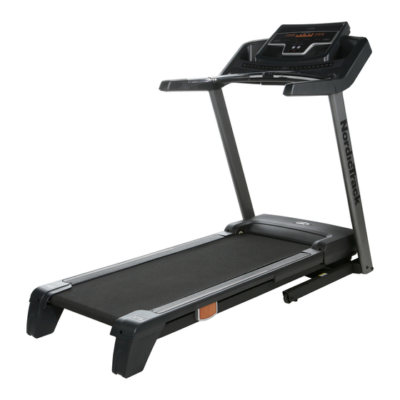
Thank you for selecting the revolutionary NordicTrack ing this manual, please see the front cover of this man- ® T9si treadmill. The T9si treadmill offers a selection of ual. To help us assist you, note the product model features designed to make your workouts at home number and serial number before contacting us. -
Page 6: Assembly
ASSEMBLY Assembly requires two persons. Set the treadmill in a cleared area and remove all packing materials. Do not dispose of the packing materials until assembly is completed. Note: The underside of the treadmill walking belt is coated with high-performance lubricant. During shipping, some lubricant may be transferred to the top of the walking belt or the shipping carton. - Page 7 2. With the help of a second person, carefully tip the treadmill onto its left side. Partially fold the Frame (57) so that the treadmill is more stable; do not fully fold the Frame yet. Remove and discard the two indicated bolts (A) Hole and the shipping bracket (B).
- Page 8 5. Press a Base Cap (88) into the Base (95). Hold a Bolt Spacer (25) inside the lower end of the Right Upright (86). Insert a 3/8" x 4" Bolt (6) with a 3/8" Star Washer (10) into the Right Upright and the Bolt Spacer.
- Page 9 8. Set the console assembly face down on a soft surface to avoid scratching the console assem- Console Wire bly. Identify the Right Handrail (105), which is Holes marked with a sticker. Hold the Right Handrail near the console assembly. Console Assembly Next, insert the console wire through the indi-...
- Page 10 11. Identify the Left Accessory Tray (112) and the Right Accessory Tray (116). Attach the Left Accessory Tray and the Right Accessory Tray to the console assembly with eight #8 x 1/2" Screws (2). Console Assembly 12. Have a second person hold the console assem- bly near the Uprights (85, 86).
- Page 11 13. Attach the console assembly to the Uprights (85, 86) with four 3/8" x 1 1/4" Bolts (7) and four 3/8" Star Washers (10). Start all four Bolts be- Console fore tightening any of them. Assembly See steps 5 and 7. Fully tighten the four 3/8" x 4"...
- Page 12 15. Raise the Frame (57) to the position shown. Have a second person hold the Frame until this step is completed. Orient the Storage Latch (54) so that the large barrel and the Latch Knob (55) are in the posi- tions shown.
-
Page 13: Operation And Adjustment
OPERATION AND ADJUSTMENT THE PRE-LUBRICATED WALKING BELT Your treadmill features a walking belt coated with high-performance lubricant. IMPORTANT: Never apply sili- cone spray or other substances to the walking belt or the walking platform. Such substances will deterio- rate the walking belt and cause excessive wear. HOW TO PLUG IN THE POWER CORD This product must be earthed. - Page 14 CONSOLE DIAGRAM Audio Jack FEATURES OF THE CONSOLE patible with iFit cards containing workouts designed to help you achieve specific fitness goals. For example, The treadmill console offers an impressive selection of lose unwanted pounds with the 8-week Weight Loss features designed to make your workouts more effec- workout.
- Page 15 HOW TO TURN ON THE POWER HOW TO USE THE MANUAL MODE IMPORTANT: If the treadmill has been exposed to 1. Insert the key into the console. cold temperatures, allow it to warm to room tem- perature before turning on the power. If you do not See HOW TO TURN ON THE POWER at the left.
- Page 16 5. Follow your progress with the displays. Before using the handgrip The matrix—When you pulse sensor, select the manual remove the mode, the matrix will sheets of clear display a track that rep- plastic from the resents 402 meters (1/4 metal contacts.
- Page 17 HOW TO USE A PRESET WORKOUT new speed and/or incline setting will appear in the displays for a few seconds. All segments will then 1. Insert the key into the console. move one column to the left. The treadmill will auto- matically adjust to the new speed and/or incline set- See HOW TO TURN ON THE POWER on page 15.
- Page 18 HOW TO USE A HEART RATE WORKOUT get heart rate setting may be programmed for con- secutive segments. CAUTION: During each segment of the workout, the console If you have heart prob- will compare your heart rate to the target heart rate lems, or if you are over 60 years of age and setting for that segment.
- Page 19 HOW TO CREATE A CUSTOM WORKOUT When the first segment of the workout ends, a se- ries of tones will sound and the current speed and 1. Insert the key into the console. incline settings will be saved in memory. Program a speed setting and an incline setting for the sec- See HOW TO TURN ON THE POWER on page 15.
- Page 20 HOW TO USE A CUSTOM WORKOUT cline setting for the current segment, simply press the Speed or Incline buttons. When the current 1. Insert the key into the console. segment ends, the new setting will be saved in mem- ory. To increase the length of the workout, first See HOW TO TURN ON THE POWER on page 15.
- Page 21 HOW TO USE AN IFIT WORKOUT If the speed or incline setting is too high or too low at any time during the workout, you can manually iFit cards are available separately. To purchase iFit override the setting by pressing the Speed or Incline buttons;...
- Page 22 THE INFORMATION MODE HOW TO ADJUST THE CUSHIONING SYSTEM The console features an information mode that keeps The treadmill features a cushioning system that re- track of the total distance that the walking belt has duces the impact as you walk or run on the treadmill. moved and the total number of hours that the treadmill To increase the firmness of the walking platform, step has been used.
-
Page 23: How To Fold And Move The Treadmill
HOW TO FOLD AND MOVE THE TREADMILL HOW TO FOLD THE TREADMILL FOR STORAGE Before folding the treadmill, adjust the incline to the lowest position. If you do not do this, you may damage the treadmill when you fold it. Remove the key and unplug the power cord. -
Page 24: To Lower The Treadmill For Use
HOW TO LOWER THE TREADMILL FOR USE 1. Hold the upper end of the treadmill with your right hand. Pull the latch knob to the left and hold it. It may be neces- sary to push the frame forward as you pull the knob to the left. -
Page 25: Troubleshooting
TROUBLESHOOTING Most treadmill problems can be solved by following the steps below. Find the symptom that applies, and follow the steps listed. If further assistance is needed, please see the front cover of this manual. PROBLEM: The power does not turn on SOLUTION: a. - Page 26 Remove the three #8 x 3/4" Pan Head Screws (1) and carefully pivot the Motor Hood (63) off. Locate the Reed Switch (77) and the Magnet (51) on the left side of the Pulley (52). Turn the Pulley until the Magnet is aligned with the Reed Switch. Make sure that the gap between the Magnet and 1/8 in.
- Page 27 PROBLEM: The walking belt is off-center or slips when walked on SOLUTION: a. If the walking belt is off-center, first remove the key and UNPLUG THE POWER CORD. If the walking belt has shifted to the left, use the hex key to turn the left rear roller bolt clockwise 1/2 of a turn;...
-
Page 28: Exercise Guidelines
EXERCISE GUIDELINES WARNING: Burning Fat—To burn fat effectively, you must exer- cise at a low intensity level for a sustained period of Before beginning this time. During the first few minutes of exercise, your or any exercise program, consult your physi- body uses carbohydrate calories for energy. -
Page 29: Part List
PART LIST—Model No. NETL99809.1 R1109A To locate the parts listed below, see the EXPLODED DRAWING near the end of this manual. Key No. Qty. Description Key No. Qty. Description #8 x 3/4" Pan Head Screw Magnet #8 x 1/2" Screw Drive Roller/Pulley 1/4"... - Page 30 Key No. Qty. Description Key No. Qty. Description Left Handrail Small Cover Console Crossbar Key Plate Pulse Bar Small Left Pulse Sensor Left Bottom Handrail Cover Large Left Pulse Sensor Right Handrail Console Back Right Handrail Insert Access Door Right Handrail Cover Console Ground Wire Right Bottom Handrail Cover Large Right Pulse Sensor...
-
Page 31: Exploded Drawing
EXPLODED DRAWING A—Model No. NETL99809.1 R1109A... - Page 32 EXPLODED DRAWING B—Model No. NETL99809.1 R1109A...
- Page 33 EXPLODED DRAWING C—Model No. NETL99809.1 R1109A...
- Page 34 EXPLODED DRAWING D—Model No. NETL99809.1 R1109A...
- Page 35 EXPLODED DRAWING E—Model No. NETL99809.1 R1109A...
-
Page 36: Ordering Replacement Parts
ORDERING REPLACEMENT PARTS To order replacement parts, please see the front cover of this manual. To help us assist you, be prepared to pro- vide the following information when contacting us: • the model number and serial number of the product (see the front cover of this manual) •...