Table of Contents
Advertisement
Quick Links
Advertisement
Table of Contents
Troubleshooting

Related Manuals for Xerox Phaser 3300


Summary of Contents for Xerox Phaser 3300
-
Page 1: Service Manual
Phaser ® 3300MFP Multi Function Printer Phaser 3300MFP ® Service Manual... - Page 3 Service Manual 701P48425 ® Phaser 3300MFP Multifunction Product Warning The following servicing instructions are for use by qualified service personnel only. To avoid personal injury, do not perform any servicing other than that contained in the operating instructions, unless you are qualified to do so.
- Page 4 Xerox technical training materials and service manuals are intended for use by authorized Xerox service technicians and service partners only and are not for resale. These materials may not be distributed, copied, or otherwise reproduced without prior written consent from Xerox Corporation.
- Page 5 Service Terms Manual Terms Various terms are used throughout this manual to either provide additional information on a specific topic or to warn of possible danger present during a procedure or action. Be aware of all symbols and terms when they are used, and always read Note, Caution, and Warning statements.
- Page 6 Symbols Marked on the Product Warning. Danger invisible laser radiation when open. Avoid direct exposure to beam. Hot surface on or in the printer. Use caution to avoid personal injury. Warning. Use caution to avoid personal injury. Use caution (or draws attention to a particular component). Refer to the manual(s) for information.
-
Page 7: Power Safety Precautions
Power Safety Precautions Power Source For 115 VAC printers, do not apply more than 127 volts RMS between the supply conductors or between either supply conductor and ground. For 230 VAC printers, do not apply more than 254 volts RMS between the supply conductors or between either supply conductor and ground. - Page 8 Electrostatic Discharge Precautions Some semiconductor components, and the respective sub-assemblies that contain them, are vulnerable to damage by Electrostatic Discharge (ESD). These components include Integrated Circuits (ICs), Large-Scale Integrated circuits (LSIs), field-effect transistors, and other semiconductor chip components. The following techniques will reduce the occurrence of component damage caused by static electricity.
-
Page 9: General Guidelines
Service Safety Summary General Guidelines For qualified service personnel only: Refer also to the preceding “Power Safety Precautions” on page v. Use care when servicing with power: Dangerous voltages may exist at several points in this product. To avoid personal injury, do not touch exposed connections and components while power is On. - Page 10 Do not install a Fuse of a different type or rating. Installing the wrong type or rating of Fuse can cause overheating and a risk of fire. Part Replacement Only use genuine Xerox approved spare parts or components to maintain compliance with legislation and safety certification. Reassembly Precautions Use extreme care during assembly.
- Page 11 Servicing Electrical Components Before starting any service procedure, switch the printer power Off and unplug the power cord from the wall outlet. If you must service the printer with power applied, be aware of the potential for electrical shock. Warning Do not touch any electrical component unless you are instructed to do so by a service procedure.
- Page 12 When shipping the printer, repack the printer using the original packing material and boxes or a Xerox packaging kit. Instructions for repacking the printer are included in the kit. If you do not have all the original packaging, or are unable to repackage the printer, contact your local Xerox service representative.
-
Page 13: Regulatory Information
Consult the dealer or an experienced radio/television technician for help. Any changes or modifications not expressly approved by Xerox could void the user's authority to operate the equipment. To ensure compliance with Part 15 of the FCC rules, use shielded interface cables. -
Page 14: European Union
European Union The CE mark applied to this product symbolizes Xerox’s declaration of conformity with the following applicable Directives of the European Union as of the dates indicated: December 15, 2004: Council Directive 2004/108/EC as amended. Approximation of the laws of the member states related to electromagnetic compatibility. - Page 15 Manual Organization The Phaser 3300MFP Multifunction Product Service Manual is the primary document used for repairing, maintaining, and troubleshooting the printer. Use this manual as your primary resource for understanding the operational characteristics of the printer and all available options. This manual describes specifications, theory, and the diagnosis and repair of problems occurring in the print engine and attached options.
- Page 16 Phaser 3300MFP Service Manual...
-
Page 17: Table Of Contents
Contents Contents 1 General Information Printer Introduction and Overview ..............1-2 Technical Support Information . - Page 18 Contents S/W Descriptions ................2-36 Overview .
- Page 19 Contents Copy Problems ................4-16 White Copy .
- Page 20 Contents 7 Cleaning and Maintenance Service Maintenance Procedure..............7-2 Recommended Tools.
- Page 21 Xerox Supplies and Accessories ........
- Page 22 Contents Interconnection Diagrams ..............10-7 Block Diagram .
-
Page 23: General Information
General Information In this chapter… Printer Introduction and Overview Printer Configuration Parts of the Printer Printer Options Maintenance Items Consumables Specifications CentreWare IS Chapter... -
Page 24: Printer Introduction And Overview
320 MB maximum. A 250-Sheet Feeder (Tray 2) is available as an option. Technical Support Information The Xerox Phaser 3300MFP Multifunction Product Service Manual is the primary document used for repairing, maintaining, and troubleshooting the MFP. To ensure complete understanding of this product, participation in Xerox Phaser 3300MFP Service Training is strongly recommended. -
Page 25: Printer Configuration
General Information Printer Configuration The Phaser 3300MFP printer is configured as follows. Features Configuration Processor and Clock Speed 300 MHz Memory Configuration* 64 + 32 MB Duplex Unit Standard Print Speed Simplex (ppm) 30ppm/Ltr, 28ppm/A4 (600 dpi) Duplex (ipm) 21ipm/Ltr, 19ipm/A4 (600dpi) Printer Resolutions (dpi) Normal 600 x600... -
Page 26: Parts Of The Printer
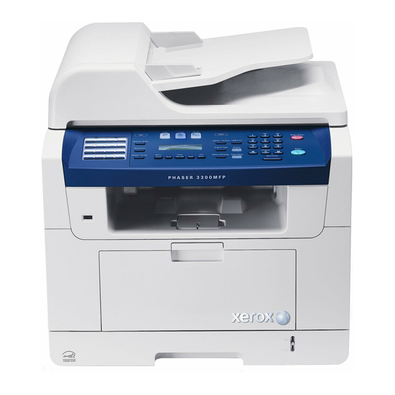
General Information Parts of the Printer Front View s3300mfp-183 ADF (automatic document feeder) Tray 1 Document width guides Optional tray 2 Document input tray Multi-purpose tray Scanner lid Output support Document output tray USB memory port Control panel Multi-purpose tray extension Output tray Multi-purpose tray paper width guides Front cover... -
Page 27: Rear View
General Information Rear View s3300mfp-184 Control Board Cover Extension telephone socket (EXT) Network port Duplex unit USB port Power receptacle Optional tray 2 cable connector Power switch Telephone line socket (LINE) Rear cover Phaser 3300MFP Service Manual... -
Page 28: Duplex Unit
General Information Duplex Unit The Phaser 3300MFP includes a Duplex Unit. Users can install the Duplex Unit without using any tools. s3300mfp-152 The Phaser 3300MFP can be used with a wired LAN. LED State Printer State Active LED Random Blink Normal NPC &... -
Page 29: Control Panel
General Information Control Panel Copy Scan COPY Stop/Clear Address Book Lighten/Darken USB Print PQRS WXYZ Resolution Original Type Duplex Start Symbols Menu Enter Exit Reduce/Enlarge Toner Saver Redial/Pause Manual Dial s3300mfp-163 Button Description Button Description Speed buttons: Allows you to store frequently-dialed Exit: Sends you back to the upper menu level. -
Page 30: Printer Options
General Information Printer Options The Phaser 3300MFP printer options include: Additional Memory (256 MB) 250-Sheet Feeder (Tray 2) Additional Memory The standard 96 MB memory consists of 64 MB soldered to the board plus a 32 MB RAM DIMM in the memory slot. The one memory slot supports up to 256 MB for a maximum of 320 MB. -
Page 31: Maintenance Items
General Information Maintenance Items The cycle period outlined below is a general guideline for maintenance. The example list is for an average usage of 50 transmitted and received documents per day. Environmental conditions and actual use will vary. The cycle period given below is for reference only. Component Replacement Cycle ADF Rubber Pad... -
Page 32: Specifications
General Information Specifications General Specifications Characteristic Specification Remarks Major Features As Standalone: Copier, Printer, Scan, Scan to USB, Fax As Network connected: Network Print, Network Scan, Scan to E- mail, Scan to SMB, Scan to FTP Size (W*D*H) w/o Hand Set 460 x 435 x 450 mm (17.7 x 17.1 x 18inch) Net Weight (incl. - Page 33 General Information Characteristic Specification Remarks Periodic Replacing Pickup Roller 150,000 Pages Pad Unit (Tray) 150,000 pages Pad Unit (ADF) 20,000 Pages Transfer Roller 70,000 Pages Fuser Unit 80,000 Pages ADF Roller 60,000 Pages Device Memory Standard / Max. 96MB / 320MB(Std./Max) Standard memory is 64MB + 32MB expansion;...
-
Page 34: Print Specifications
General Information Print Specifications Characteristic Specification Remarks Print Speed, Simplex 30ppm/Ltr, 28ppm/A4 (600 dpi) Print Speed, Duplex 21ipm/Ltr, 19ipm/A4 (600dpi) Usable paper sizes Letter, A4, Folio, Legal, Oficio Print Emulation PCL6, PS3 Auto Emulation Sensing Font Type 45 Scalable, 1 Bitmap Power Save Yes (5/10/15/30/45min.) Resolution... - Page 35 General Information Characteristic Specification Remarks Halftone 256 level for only optical resolution Scan Size (Max. Document Width) Max.216mm (8.5") Scan Size (Effective Scan Width) Max 208mm (8.2inch) Scan-to Scan-to- Application, Scan- to-USB Scan Depth Color (24 bit) Scan Depth Mono (1bit for Line art, 8 Bit for Gray scale) Copy Quality...
- Page 36 General Information Characteristic Specification Remarks Changeable Default mode Contrast, Image, Reduce/Enlarge, No. of Copies Special Copy (N-up copy) 2-up, 4-up (ADF only) Special Copy (Auto Fit Copy) Yes (Platen only) Special Copy (AID Copy) Yes (Platen only) * Copy 2-side printed original document into one page (ex.
-
Page 37: Telephone Specifications
General Information Telephone Specifications Telephone Specifications Characteristic Specification Remarks Handset On hook Dial Search Yes (Phone Book) by using Phone Book Button 1-Touch Dial 30EA Speed Dial 200 locations Total locations can be stored TAD I/F Tone/Pulse Selectable in Tech mode Pause Auto Redial... - Page 38 General Information Characteristic Specification Remarks Compression MH/MR/MMR/ JPEG/JBIG Color Fax Yes (Sending Only) Resolution Fine 203*196dpi S.Fine 203*196dpi 300*300dpi Scan Speed (ADF) Std 2.5 sec./ LTR Fine/S.Fine 5 sec./ LTR Rx fax duplex print out Multiple page scan speed 21ppm/LTR, Std mode Receive Mode Fax, TEL, Ans/Fax,...
-
Page 39: Network Specifications
General Information Network Specifications Characteristic Specification Protocol TCP/IP (LPR, Standard TCP/IP Printing, IPP), NetWare, Ethertalk Operating System Windows 2000/XP(32/64bits)/Vista(32/64bits)/2003 Server(32/64bits) Mac OS 10.3 and above Various Linux OS (via USB interface only) including Red Hat 8~9, Fedora Core 1~4, Mandrake 9.2~10.1, and SuSE 8.2~9.2 Paper Handling Specifications Characteristic Specification... -
Page 40: Print Cartridge Specifications
General Information Print Cartridge Specifications Characteristic Specification Toner Type One Piece Type Print Cartridge Toner Life Initial 4Kpages (ISO 19752 Standard Test Pattern), running Standard: 4Kpages,High yield: 8K pages Toner Level Sensor Toner Count Yes (CRUM) 1-18 Phaser 3300MFP Service Manual... -
Page 41: Centreware Is
General Information CentreWare IS The CentreWare IS (CWIS) enables the user to monitor the printer’s status. User can access the CentreWare IS menu to add and/or update the printer’s information as needed. Accessing CentreWare IS 1. Open a web browser. 2. - Page 42 General Information Index button provides links to specific topics in CWIS, and a site map for rapid navigation through the CWIS site. 1-20 Phaser 3300MFP Service Manual...
-
Page 43: Theory Of Operation
Theory of Operation In this chapter... Phaser 3300MFP Operational Overview Mechanical Parts Specifications Engine F/W S/W Descriptions Chapter... -
Page 44: Phaser 3300Mfp Operational Overview
Theory of Operation Phaser 3300MFP Operational Overview The Phaser 3300MFP is a monochrome multi-function product that uses Laser Scanner Unit (LSU) with an electrophotographic process in the print engine, a moving CCD in the automatic feed scanner, and a built-in fax- modem for fax functionality. -
Page 45: Paper Path
Theory of Operation Paper Path ADF Roller Scanner Pickup Roller Feed Roller Exit Roller Exit Roller Heat Roller Engine Registration Roller MPT Roller Feed Roller Duplex Pickup Roller Pressure Roller Transfer Roller s3300mfp-164 Engine H/W Sensor Input Circuit Paper Empty Sensing The operation of the Paper empty sensor actuator (Photo Interrupter) on the HVPS reports to the CPU whether the tray is empty or not. - Page 46 Theory of Operation Paper Feed Sensing When paper passes the feed sensor actuator, the photo interrupter signals the CPU, which releases the image data after certain time. If the CPU doesn’t detect the feed sensor within 1sec. after paper is fed, paper Jam0 occurs.
-
Page 47: Assembly Description
Theory of Operation Assembly Description Feed Section Paper Tray Feed Method: Universal Cassette Type Feed Standard: Center Loading Capacity: Cassette 250 Sheets (75 g/m , 20 lb. Standard Paper) s3300mfp-145 Multi-purpose Tray Feeding method: Multi-purpose tray (MPT) Capacity: 50 sheets (75 g/m , 20 lb. - Page 48 Theory of Operation Transfer Assembly In Warranty (Life time): Within 70.000 sheets printing s3300mfp-147 Phaser 3300MFP Service Manual...
- Page 49 Theory of Operation Driver Assembly The MAIN Motor assembly drives the Cassette, MPT, and Print Cartridge The EXIT Motor assembly drives the fuser, exit roller and the initial duplex feeding The DUPLEX Motor assembly drives the duplex feeder Main Motor Exit Motor Duplex Motor s3300mfp-148...
- Page 50 Theory of Operation Fuser Assembly Fusing Type: Halogen Lamp (R2) Heat Roller: 28.3 with 0.1 Crown Pressure Roller: Electrically conductive Thermistor - Temperature Detecting Sensor Thermostat - Overheat Protection Device s3300mfp-149 Phaser 3300MFP Service Manual...
- Page 51 Theory of Operation The LSU consists of LD (Laser Diode) and polygon motor control. When the controller generate the printing signal LD will turn on and Polygon motor starts. If the receiving part in LSU detect the beam and then Hsync is generated.
- Page 52 Theory of Operation Print Cartridge OPC Cleaning: Mechanical Cleaning by the cleaning blade Waste toner: Room for the recycled toner No shutter for protecting the OPC Drum Cleaning Roller Laser Scanning Unit (LSU) = -380V Doctor Blade -1.35KV -200V Charging Roller Cleaning Blade Developing OPC Drum...
- Page 53 Theory of Operation Duplex Unit Duplex printing function as factory option Available Paper: Letter, Oficio, Legal, Folio, and A4 s3300mfp-152 Optional Tray (SCF) For customer convenience in managing paper Capacity: 250 sheets s3300mfp-154 Phaser 3300MFP Service Manual 2-11...
-
Page 54: Mechanical Parts Specifications
Theory of Operation Mechanical Parts Specifications Frame Material: PC + ABS V0 NH-1000T (Cheil Industries) Weight: 1.0 kg Feeding Part Feeding Type: Universal Cassette Type Feeding Standard: Center Loading Feeding Capacity: Cassette 250 sheets (75 g/m , 20 lb. paper standard) MP 50 sheets (75 g/m , 20 lb. -
Page 55: Transfer Assembly
Theory of Operation Transfer Assembly The Transfer Assembly consists of the Transfer Roller and gear. The transfer roller delivers the toner from the OPC drum to the paper. ΜΩ TR Voltage: +1.3 KV ± 5% (based on 200 , in accordance with media area, Transfer table) -1.20 KV ±... -
Page 56: Fuser
Theory of Operation Process Speed Print Speed: 28/30 PPM (based on A4/LTR) OPC Drum Vp: 179.7 mm/sec. Unit Relative Velocity (Paper Speed) Pickup: 217.27 mm/sec., 21.72% C VS OPC Vp Feeder (cassette): 182.34 mm/sec., 2.15% C VS OPC Vp Feeder (Frame): 180.42 mm/sec., 1.08% C VS OPC Vp Transfer: 183.02 mm/sec. - Page 57 Theory of Operation Temperature Detecting Sensor (Thermistor) Thermistor Type: FS-50003 (SEMITEC 364 FL Type) Temperature Resistance: 7 kQ (180 °C) SYSTEM Temperature SETTING Stand by:165 ± 5 °C Printing:189 ± 5 °C (5 minutes before) 184 ± 5 °C (5 minutes after) Overshoot: 200 °C less Overheat: 210 °C less Heat Roller...
-
Page 58: Lsu (Laser Scanner Unit)
Theory of Operation Safety Features To prevent overheating 1st protection device: H/W cuts off when detecting an overheating 2st protection device: S/W cuts off when detecting overheating 3st protection device: Thermostat cuts off power to the lamp Safety device Fuser power is cut-off when the front cover is open LSU power is cut off when the front cover is open The temperature of the fuser cover's surface is maintained at less than 80ºC to protect the user and a caution label is attached where... - Page 59 Theory of Operation ± Beam Position Deviation of main scanning at the center of image 1.0 mm ± Deviation of sub scanning 1.0 mm Scan Line Max 1 mm within image height Property Skew Max 1 mm -100 ~ +100 mm range ±...
-
Page 60: Print Cartridge
Theory of Operation Print Cartridge In the print cartridge, the OPC unit and the developer unit are housed in a single case. The OPC unit consists of the OPC drum and charging roller, and the developer unit includes toner, toner chamber, supply roller, developing roller, and the blade. -
Page 61: Fax Section
Theory of Operation Regulating Blade Type: Regulating toner layer by pressure Valid Length: 228 mm Voltage: -420 V ~ -600 V Charging Portion Type: Conductive Roller Contact-Charge Rotary Velocity: 179.7 mm/sec Length: 230 mm ϕ 12.0 ± 0.05 mm ϕ Shaft OD: 6 + 0 / -0.05 mm Driver: Gear Driver... - Page 62 Theory of Operation Modem (SFX336) specification. 2-wire half-duplex fax modem modes with send and receive data rates up to 33.600 bps V.17, V.34, V.29, V.27 ter, and V.21 Channel 2 Short train option in V.17 and V.27 ter PSTN session starting V.8 and V.8 bis signaling HDLC support at all speeds Flag generation, 0-bit stuffing, ITU CRC-16 or CRC-32 calculation and...
- Page 63 Theory of Operation Signal Transition of DAA Solution Line Interface Signal of Tel Line and LSD is Analog Signal. There is A/D, D/A Converter in LSD, so Analog Signal from Tel Line is converted in Digital through A/D Converter in DAA and transfer to SSD by DIB Capacitor.
-
Page 64: Line Interface
Theory of Operation Line Interface The Line Interface provides the connection between the system and the external telephone line. Main functions are Line Interface, Telephone Connection and Line Condition Monitoring. Telephone Line Connection a) Modular Plug: RJ-11C b) LIU PBA Modular Type: 623 PCB4-4 c) Line Code Length: 2500 ±... -
Page 65: Scan Part
Theory of Operation Scan Part Pictorial signal input part: output signal of CCD passes through Bypass Cap change to ADC at HT82V26, and defined signal between HT82V26 and CHORUSm processes the Image signal. When AFE accept each pixel, CDS (Correlated Double Sampling) technique which samples arm-level twice is used on each pixel by using CIP4e signal. -
Page 66: Printer Section
Theory of Operation Printer Section The printer consists of the Engine and F/W, and engine consists of the mechanical parts that include the Frame, Feeding, Developing, Driving, Transferring, Fusing, Cabinet and H/W comprising the Control Board, power board, operation panel, PC Interface. The main controller consists of ASIC (CHORUSm) parts, Memory parts, Engine Interface parts and it functions as Bus Control, I/O Handling, drivers &... - Page 67 Theory of Operation ASIC Items Specification Process 0.13 um (STDH150) Package 496 PBGA (total pad number: 597 ea) Function pin: about 367pins PWR & GND pin: 130 pins ((130/496) x 100 = 26.2%) PWR & GND pad: 204 ea ((204/597) x 100 = 34.17%) Voltage Core Voltage: 1.2 V I/O Pad Voltage: 3.3 V...
- Page 68 Theory of Operation Items Specification I2C Controller I2C bus (SM bus) Slave Device Support (I2C Version 2.1) RTC Core Voltage: 3 V 2 PLL (MAIN/(H) PVC) ARM920T External I/O cache NAND Flash DMA Controller CIP4E Controller (16KB, 16KB) (up to BCH) Controller (Codec_DMA) AMBA...
-
Page 69: Copier Section
Theory of Operation Copier Section Copy Mode: Black and White Scanner Type; CCD with Flatbed/Platen and ADF Maximum Size of Original: Platen: 216 x 297 mm (max. width = 218 mm, ADF: Legal (216 x 356 mm) max length = 400 mm) Optical Resolution: 600 x 600 dpi Copy Quality - H x V:... -
Page 70: Smps & Hvps Board
Theory of Operation SMPS & HVPS board The SMPS supplies DC Power to the System. It takes 110 V/220 V and outputs the +5 V, +24 V to supply the power to the Control Board. The HVPS board creates the high voltage of THV/MHV/Supply/Dev and supplies it to the print cartridge for making best condition to display the image. - Page 71 Theory of Operation Input Voltage: 24 V DC ± 15% Output Voltage: -200 V ~ -600 V DC +20 V Output Voltage Fluctuation range: PWM Control Input contrast of the output stability degree: ± 5% or less Loading contrast: ± 5% or less Output Voltage Rising Time: 50 ms Max Output Voltage Falling Time: 50 ms Max Output Loading range: 10 ΜΩ...
- Page 72 Theory of Operation Rated Frequency: 50/60 Hz Frequency Fluctuating range: 47 ~ 63 Hz Input Current: Under 4.0 Arms/2.0 Arms (But, the status when e-coil is off or rated voltage is inputted/outputted) Rated Output Power NO ITEM Remark CHANNEL NAME +5 V +24.0 V CONNECTOR PIN...
- Page 73 Theory of Operation Fuse 24V Fuse 5V Fuse 5V s3300mfp-160 Length of Power Cord: 1830 ± 50 mm Power Switch: Use Feature Insulating Resistance: 100 ΜΩ or more (at DC 500V) Withstanding Voltage: Must be no problem within 1 min. (at 1000V-LV model/1500 Vac-HV model,10 mA) Leaking Current: under 3.5 mA Running Current: under 40 A PEAK (AT 25 °C, COLD START)
- Page 74 Theory of Operation Fuser AC Power Control AC power to the Fuser is controlled with a Triac, a semiconductor switch. The ON/OFF control is operated when the gate of the Triac is turned on/off by Phototriac (insulating part). When the ‘HEATER ON’ signal is turned on at engine, the LED of PC501 (Photo Triac) flashes.
-
Page 75: Engine F/W
Theory of Operation Engine F/W Control Algorithm Feeding If feeding from a cassette, the drive of the pickup roller is controlled by controlling the solenoid. The on/off of the solenoid is controlled by controlling the general output port or the external output port. While paper moves, occurrence of Jam is judged as below. - Page 76 Theory of Operation Fusing The temperature change of the heat roller’s surface varies with the resistance value through the thermistor. The resistance value determines how much voltage will be converted into heat to raise the temperature of the fuser. If the value measured by the thermistor is out of controlling range, one of the errors below may occur: Error...
- Page 77 Theory of Operation The LSU receives image data from PVC or HPVC and makes a latent image on OPC surface. It uses the dual beam, LD1 and LD2. But the control method of each is the same. Compared to the single beam, the dual beam has half of the LSU's frequency. ->The frequency of the dual beam = the frequency of the single beam /2.
-
Page 78: S/W Descriptions
Theory of Operation S/W Descriptions Overview The software of Phaser 3300MFP system is constructed with 1) Host software - the application software that operates in Windows and Web Environments. 2) Firmware - Embedded software that controls the printing job. Architecture Printer Host Software Firmware... -
Page 79: Data And Control Flow
Theory of Operation Data and Control Flow Firmware Host Driver • GDI & PCL 6 (PCL XL) Engine Kernel Web-Based • Document Management System Network • Network Administration • Status Monitor Interface • Remote Control Panel Card Stand Alone • Document Management Application System •... - Page 80 Theory of Operation In Printing, the two procedures are Using the USB Port a. When the user starts to print the desired document to a PCL or PS string, the Driver translates the all-graphic data and sends the data to the host spooler.
-
Page 81: Error Messages And Codes
Error Messages and Codes In this chapter... Introduction Jam Error Codes Error Messages Chapter... -
Page 82: Introduction
Error Messages and Codes Introduction This chapter describes error messages that appear on the CWIS status window or the Control Panel display to indicate the machine’s status or errors. These error indications serve as the entry point into the troubleshooting process. - Page 83 Error Messages and Codes Check and Cause Solution 3. If continuous clusters occur, check 3. Replace the Housing-Pickup and/or whether the assembly slot between shaft- Shaft-Pickup. pickup and housing-pickup become open or is broken away. 4. If the paper feeds into the printer and Jam 0 occurs, check feed-sensor of the Control Board.
- Page 84 Error Messages and Codes JAM 2 Description 1. Paper is jammed in front of or inside the fuser. 2. Paper is stuck in the discharge roller and in the fuser just after passing through the Actuator-Feed. Fuser Toner Cartridge Exit Sensor MP Sensor Pressure Roller Transfer Roller...
-
Page 85: Duplex Jam 0
Error Messages and Codes Check and Cause Solution 3. Paper is accordion jammed in fuser. 3. Remove the jammed paper after disassembling the fuser: Clean the surface of the pressure roller with dry cloth. Remove the toner dust on the rib. Check the assemblage and performance of the exit assembly. - Page 86 Error Messages and Codes Duplex Jam 0 Description The 'Duplex Jam 0' message is displayed in the LCD window. s3300mfp-071 Check and Cause Solution 1. Paper cannot pass the Duplex sensor. 1. Replace a HVPS or Control Board. 2. Paper cannot reach the registration 2.
-
Page 87: Error Messages
Error Messages and Codes Error Messages Messages appear in the CentreWare IS window or on the control panel display to indicate the machine’s status or errors. Refer to the tables below to understand the messages’ meaning and correct the problem if necessary. Messages and their meanings are listed in alphabetical order. - Page 88 The server address you have entered is Enter the correct server address. invalid. Invalid Cartridge The print cartridge you have installed is not Install a Xerox-genuine print cartridge, designed for compatible with your machine. your machine. Line Busy The receiving fax machine did not answer Try again after a few minutes.
- Page 89 Error Messages and Codes Message Meaning Suggested solutions Not Assigned The speed button or speed dial number Enter the number or email address manually using you tried to use has no number or e-mail the number keypad or store the number or address. address assigned to it.
- Page 90 Error Messages and Codes Message Meaning Suggested solutions Power Failure Power has turned off then on and the The job which you were trying to do before the power machine's memory has not been back up. failure must be completely re-done. Replace Toner The print cartridge installed is not a Replace the print cartridge with a new one.
- Page 91 Error Messages and Codes Message Meaning Suggested solutions Nongenuine Toner The print cartridge installed is not a This message appears when you selected stop at the Replace Toner genuine cartridge. Non Genuine Toner prompt. Install the genuine print cartridge. Toner Exhausted A STOP The life span of the print cartridge is You can select either stop or continue.
- Page 92 Error Messages and Codes 3-12 Phaser 3300MFP Service Manual...
-
Page 93: General Troubleshooting
General Troubleshooting In this chapter... Procedure for Checking the Symptoms Tech Mode Paper Feeding Problems Printing Problems (Malfunction) Fax & Phone Problems Copy Problems Scanning Problems Print Cartridge Service Network Problems Troubleshooting Abnormal Image Printing and Defective Roller Chapter... -
Page 94: Procedure For Checking The Symptoms
General Troubleshooting Procedure for Checking the Symptoms Before attempting to repair the printer first obtain a detailed description of the problem from the customer. Power On - No Power - Power Module error Control Panel - Main PBA error - LCD Panel error Refer to Indicate Ready or... -
Page 95: Tech Mode
General Troubleshooting Tech Mode How to Enter Tech Mode In service (tech) mode, the technician can check the machine and perform various test to isolate the cause of a malfunction. While in Tech mode, the machine still performs all normal operations. To enter the Tech mode Menu Menu... - Page 96 General Troubleshooting DIAL MODE This function can choose dial method. *Default: Dial (Dial/Pulse) MODEM SPEED You can set the maximum modem speed. Communication is done with modem speed automatically set at lower speed when communicating with a slower speed modem since communication is done on the standard of the side where modem speed is low for transmission/ reception.
-
Page 97: Machine Test
General Troubleshooting Country Group USA/Canada Russia South Africa Country USA/Canada Russia South Africa Mexico Germany India Brazil France Oman Italy Poland Spain Bangladesh Austria Kuwait Netherlands Morocco Belgium Algeria Portugal Pakistan Sweden Norway Bahrain Denmark Sri Lanka Finland Saudi Arabia Switzerland Chile Greece... - Page 98 General Troubleshooting Pattern Test Using this test pattern, you can check if the printer mechanism is functioning properly. It is needed in the production progress. Service person doesn't need to use it. Shading Test The function is to get the optimum scan quality by the specific character of the CCD (Charge Coupled Device).
-
Page 99: Report
General Troubleshooting Report Protocol List This list shows the sequence of the CCITT group 3 T.30 protocol during the most recent sending or receiving operation. Use this list to check for send and receive errors. If a communication error occurs while the machine is in TECH mode, the protocol list will print automatically. -
Page 100: Paper Feeding Problems
General Troubleshooting Paper Feeding Problems Wrong Print Position Printing begins when the paper is in the wrong position. Check and Cause Solution A defective feed sensor actuator can Replace the defective actuator. cause incorrect timing. Multi-Feeding Multiple sheets of paper are fed at once. Check and Cause Solution 1. -
Page 101: Paper Rolled In The Opc
General Troubleshooting Paper rolled in the OPC Paper is rolled up in the OPC. Check and Cause Solution 1. Paper is too thin. 1. Recommend to use normal paper thickness. 2. The face of paper is curled. 2. How to remove the rolled paper in the OPC. -
Page 102: Printing Problems (Malfunction)
General Troubleshooting Printing Problems (Malfunction) Defective Operation (LCD WINDOW) Display Strange characters are displayed on the Control Panel and buttons are not operated. Check and Cause Solution 1. Clear the memory. 1. Try again after clearing the memory. 2. Check if OPE HARNESS is connected 2. -
Page 103: Paper Empty Without Indication
General Troubleshooting Paper Empty without indication The paper empty status on the Control Panel is not displayed when the paper tray is empty. Check and Cause Solution 1. Bending or deformation of the actuator 1. Replace the defective actuator. of the paper sensor. 2. -
Page 104: No Power
General Troubleshooting No Power When system power is turned on, the Control Panel LEDs do not come on. Check and Cause Solution 1. Check if the power input and SMPS 1. Replace the power supply cord or output are normal. SMPS. -
Page 105: Fax & Phone Problems
General Troubleshooting Fax & Phone Problems No Dial Tone While Manual Dial button is pressed, there is no dial tone. Check and Cause Solution 1. Check if the telephone line cord is 1. If the telephone cord is normal but connected to TEL LINE correctly. -
Page 106: Defective Fax Forward/Receive
General Troubleshooting Defective FAX FORWARD/RECEIVE FAX FORWARD/RECEIVE is not functioning. Check and Cause Solution 1. Listen for a dial tone by pressing 1. If the MODEM testing is normal and Manual Dial. there is no dial tone, then replace the LIU Board. -
Page 107: Defective Fax Receive (2)
General Troubleshooting Defective FAX RECEIVE (2) The received data is distorted or cut-off when printed. Check and Cause Solution 1. Check if there is NOISE when pressing 1. If it makes NOISE, rearrange the Manual Dial. telephone line. (Refer to ‘Defective FAX RECEIVE’.) 2. -
Page 108: Copy Problems
General Troubleshooting Copy Problems White Copy Blank page is printed out when in Copy mode. Check and Cause Solution 1. Check if the Scan-Cover is open. 1. Room light can pass through a thin original. 2. Check shading profile. 2. Correct the shading profile in Tech Mode. -
Page 109: Defective Image Quality
General Troubleshooting Defective Image Quality The copied image is light or defective. Check and Cause Solution 1. Check shading profile. 1. Correct the shading profile in Tech Mode. 2. Check the gap between original and 2. A gap greater than 0.5 mm can cause a scanner glass. -
Page 110: Print Cartridge Service
General Troubleshooting Print Cartridge Service Safekeeping of the Print Cartridge Excessive exposure to direct light more than a few minutes may cause damage to the cartridge. Service for the Life of the Print Cartridge If the printed image is light due to the life of the toner, you can temporarily improve the print quality by redistributing the toner (Shake the print cartridge), however, you should replace the print cartridge to solve the problem thoroughly. - Page 111 General Troubleshooting s3300mfp-073 4. Save the box and the cover for shipping. Slide the new print cartridge in until it locks into place. s3300mfp-074 5. Close the front cover. s3300mfp-075 Phaser 3300MFP Service Manual 4-19...
-
Page 112: Print Cartridge Problems
General Troubleshooting Print Cartridge Problems Defect Symptom Cause & Check Solution Light image and The printed image 1. If the image is light or unclean and 1. All of 1, 2, 3, 4: is light or unclean and partially blank image untidy - (1) The weight of the print cartridge untidy. - Page 113 General Troubleshooting Defect Symptom Cause & Check Solution White/Black spots Light or dark black 1. If light or dark periodical black dots 1. In case of 1 above: dots on the image occur, this is because the print Run OPC Cleaning Mode Print 4-5 occur periodically.
- Page 114 General Troubleshooting Defect Symptom Cause & Check Solution Ghost & Image The printed image 1. The printed image is too light 1. All of 1, 2, 3 above: is too light or dark, or Contamination or dark, or partially contaminated (1) Remove toner and foreign partially contaminated black.
-
Page 115: Network Problems Troubleshooting
General Troubleshooting Network Problems Troubleshooting General Problems Problem Solution System does not function with Possibly the network parameters are corrupted. some wrong values entered by Restart the system and set to factory defaults on the mistake while configuring. printer front panel or on your computer using CWIS. Print server does not print 1. - Page 116 General Troubleshooting Problem Solution Firmware upgrade process An IP address should be assigned to upgrade the is completed. But Firmware. Make sure that IP address is entered in Print upgrading is not executed. Server. If an IP address is not entered, reassign it and try again.
-
Page 117: Abnormal Image Printing And Defective Roller
General Troubleshooting Abnormal Image Printing and Defective Roller If abnormal image prints periodically, check the parts shown below. s3300mfp-169 1. OPC Drum 5. Transfer Roller 2. Charge Roller 6. Heat Roller 3. Supply Roller 7. Pressure Roller 4. Developing Roller No Roller Abnormal image period Kind of abnormal image OPC Drum... - Page 118 General Troubleshooting 4-26 Phaser 3300MFP Service Manual...
-
Page 119: Print-Quality Troubleshooting
Print-Quality Troubleshooting In this chapter... Print-Quality Problems Overview Checklist Before Troubleshooting Print-Quality Print-Quality Specifications Print-Quality Troubleshooting Chapter... -
Page 120: Print-Quality Problems Overview
Print-Quality Troubleshooting Print-Quality Problems Overview Print-quality defects can be attributed to printer components, consumables, media, internal software, external software applications, and environmental conditions. To successfully troubleshoot print-quality problems, eliminate as many variables as possible. The first step is to generate prints using information pages embedded in the printer on laser paper from the approved media list. - Page 121 Print-Quality Troubleshooting Fuser “Ghost (2)” on page 5-15 “Stains on back of the page” on page 5-16 Print Cartridge “Light Image” on page 5-12 “Dark or Black Image” on page 5-13 “Uneven Density” on page 5-13 “Background” on page 5-14 “Ghost (1)”...
-
Page 122: Checklist Before Troubleshooting Print-Quality
Print-Quality Troubleshooting Checklist Before Troubleshooting Print-Quality Checking the Printer Condition Toner Low toner can cause print-quality problems, such as Fading, Streaking, White Lines, or Dropouts. Print a small document from different software applications to replicate the problem and check the amount of toner available. If the toner is low, you can extend the Print Cartridge life by removing the Print Cartridge (page 8-18) from the printer, and gently shake the Print Cartridge from side-to-side to distribute toner. -
Page 123: Checklist Before Troubleshooting Image Quality
Print-Quality Troubleshooting Checklist Before Troubleshooting Image Quality Check the following items prior to performing troubleshooting. These procedures may help to resolve the problems without troubleshooting the printer. 1. Clean the Laser Unit window using a Q-tip or a dry, lint-free cloth to wipe the window. - Page 124 Print-Quality Troubleshooting The job prints, but the top and side margins are incorrect. Image Not Centered a. Ensure the Media Size settings in the Tray Settings are correct. b. Ensure the margins are set correctly in your software application. c. Perform internal test prints (i.e., printer’s Demo Page, etc.,) and evaluate the prints.
-
Page 125: Print-Quality Specifications
The print-quality is best when quality paper is fed from the tray. The print quality is evaluated on the maximum size of each standard paper. Color Print Quality: Xerox-brand Color XPressions paper Black and White Quality: Xerox-brand 4200 paper Paper Condition Paper should be fresh and stored in the operating environment for 12 hours before use for printing. -
Page 126: Print-Quality Troubleshooting
Print-Quality Troubleshooting Print-Quality Troubleshooting Print-Quality Defect Definitions The following table lists the print-quality defect corrective procedure, their definition, and the page where each corrective procedure is provided. Page Defect Definition Light Image The overall image density is too light. page 5-12 Dark or Black Image The entire image area is black. -
Page 127: Repeating Defect Measurement
Print-Quality Troubleshooting Repeating Defect Measurement When horizontal lines and/or spots occurs periodically, it is possibly caused by a defect on a particular roller. Measure the interval of the defect on the test print and check the relation to the roller in the table. The interval does not necessarily match the circumference of the roller. -
Page 128: Vertical Black Line And Band
Print-Quality Troubleshooting Vertical Black Line and Band Straight thin black vertical line occurs in the printing. Dark black vertical band occur in the printing. Check and Cause Solution Damaged develop roller in the print If causes 1 and 2 occur in the print cartridge. -
Page 129: Horizontal Black Band
Print-Quality Troubleshooting Horizontal Black Band Dark or blurry horizontal stripes occur in the printing periodically. (They may not occur periodically.) Check and Cause Solution Bad contacts of the voltage terminals to Clean each voltage terminal of the print cartridge. Charge, Supply, Develop and Transfer roller. -
Page 130: Black/White Spot
Print-Quality Troubleshooting Black/White Spot Dark or blurry black spots occur periodically in the printing. White spots occur periodically in the printing. Check and Cause Solution If dark or blurry black spots occur Run OPC cleaning Mode Print and run periodically, the rollers in the Print the Self-test 2 or 3 times. -
Page 131: Dark Or Black Image
Print-Quality Troubleshooting Dark or Black Image The printed image is dark. Check and Cause Solution No charge voltage in the Control Board. Clean the high voltage charge terminal. Charge voltage is not turned on due to Check the state of the connector which Digital Printer the bad contacts between power supply connects the Control Board and HVPS. -
Page 132: Background
Print-Quality Troubleshooting Background Light dark background appears in whole area of the printing. Check and Cause Solution Recycled paper has been used. Quality is not guaranteed when using recycled paper. Digital Printer The life of the Print Cartridge has Replace the print cartridge. Digital Printer expired. -
Page 133: Ghost (2)
Print-Quality Troubleshooting Ghost (2) Ghost image occurs at 75.5 mm intervals of the OPC drum on the output when printing on card stock or transparencies using manual feeder. Check and Cause Solution When printing on card stock thicker than Select 'Thick Mode' on paper type menu normal paper or transparencies, higher from the software application. -
Page 134: Stains On The Front Of The Page
Print-Quality Troubleshooting Stains on the front of the page The background on the face of the printed page is stained. Check and Cause Solution Toner leakage due to improperly sealed Replace the print cartridge. print cartridge. Digital Printer If the Transfer Roller is contaminated, If the Transfer Roller is contaminated, Digital Printer stains on the face of page will occur. -
Page 135: Blank Page Print Out (1)
Print-Quality Troubleshooting Blank Page Print Out (1) Blank page is printed. Check and Cause Solution Bad ground contacts in OPC and/or print Remove contamination on the terminals cartridge. of the print cartridge and the printer. Digital Printer Digital Printer Digital Printer Digital Printer Digital Printer Blank Page Print Out (2) - Page 136 Print-Quality Troubleshooting 5-18 Phaser 3300MFP Service Manual...
-
Page 137: Adjustments And Calibrations
Adjustments and Calibrations In this chapter... Altitude Adjustment Note The Altitude Adjustment might not be available for the Phaser 3300MFP immediately after product launch. If the adjustment is not available as described in these procedures, verify that the machine has the most current version of firmware installed. -
Page 138: Altitude Adjustment
Adjustments and Calibrations Altitude Adjustment Print Quality is affected by atmospheric pressure, which is determined by the location of the printer above sea level. The following information contains instructions and specifications for adjusting altitude information for the Phaser 3300MFP. Note Verify that the Phaser 3300MFP printer driver has been installed. -
Page 139: Printer Settings Utility Method (Usb Connection Only)
Adjustments and Calibrations Printer Settings Utility Method (USB Connection Only) 1. From the Start Menu, select Programs > Xerox Phaser 3300MFP >Printer Settings Utility. 2. The Printer Settings Utility window is displayed. a. In the left column, select Setting. b. In the right column, select Altitude Adjustment. - Page 140 Adjustments and Calibrations Phaser 3300MFP Service Manual...
-
Page 141: Cleaning And Maintenance
Cleaning and Maintenance In this chapter... Service Maintenance Procedure Cleaning Maintenance Software Maintenance Flash Upgrade Resetting Firmware Chapter... -
Page 142: Service Maintenance Procedure
Cleaning and Maintenance Service Maintenance Procedure Perform the following procedures whenever you check, service, or repair a printer. Cleaning the printer, as outlined in the following steps, assures proper operation of the printer and reduces the probability of having to service the printer in the future. -
Page 143: Cleaning The Print Cartridge
Cleaning and Maintenance 8. Remove and clean the paper trays. 9. Clean all rubber rollers with a lint-free cloth slightly dampened with cold water. Cleaning the Print Cartridge Caution Do not expose the Print Cartridge to light for more than 5 minutes. Cover the Print Cartridge to avoid damage. -
Page 144: Cleaning The Laser Unit
Cleaning and Maintenance Cleaning the Laser Unit Caution Do not expose the Print Cartridge to light for more than 5 minutes. Cover the Print Cartridge to avoid damage. 1. Open the Front Cover. 2. Remove the Print Cartridge (page 8-18). Note It may be difficult to locate the strip of glass on the Laser Unit. -
Page 145: Maintenance
Cleaning and Maintenance Maintenance RIP (Repair, Inspect, and Prevent) Procedure Perform these routine maintenance procedures during the course of servicing the printer. Clean the Feed Rollers, Exit Rollers, and Guides; replace if necessary. Remove and clean the paper trays. Print a Configuration and Error History pages; diagnose, and repair any problems as indicated. -
Page 146: Software Maintenance
Cleaning and Maintenance Software Maintenance Clearing the Memory You can selectively clear information stored in the machine's memory. 1. Press Menu on the control panel and scroll left or right to System Setup; press Enter. 2. Scroll left or right until Clear Setting appears on the bottom line; press Enter. -
Page 147: Flash Upgrade
Flash Upgrade There are two methods for upgrading firmware, USB and Network. 1. Down load the applicable files from the Xerox support web site. Unzip (decompress) the files. 2. Be sure your appropriate firmware updating option (Network or USB) is available and connected. -
Page 148: Network Connection
Cleaning and Maintenance Network Connection This method uses CentreWare IS to upgrade the firmware over the network connection. 1. Ensure the printer is connected to the computer with a network connection. 2. Verify that you have downloaded the *.fls file. 3. - Page 149 Cleaning and Maintenance 8. Click the Browse button and locate the “*.hd” file on your computer. Select the “*.hd” file and click Open. 9. Click the Blue button to start the firmware update process. 10. A status window is displayed. 11.
-
Page 150: Resetting Firmware
Cleaning and Maintenance Resetting Firmware USB Connection 1. Ensure the printer is connected to the computer with a USB connection. 2. Verify that you have downloaded the reset_xerox.Lt file. 3. At the DOS Prompt, verify that you’re at the root directory of the files. Type usblist2 reset_xerox.Lt and press Enter. - Page 151 Cleaning and Maintenance 6. The About Printer page is displayed. On the left side, expand General, and click Resets. 7. The Resets window is displayed. Select the appropriate option to restore the printer information. 8. Click Restore Defaults. Phaser 3300MFP Service Manual 7-11...
- Page 152 Cleaning and Maintenance 9. The Microsoft Internet Explorer window is displayed confirming restoring the Printer Default/Network Default information. Click OK. Printer Default Network Default 10. For Restoring Network Default, a message window is displayed. Click OK. 11. The Completion window is displayed. Click OK to close the window. 12.
-
Page 153: Service Parts Disassembly
Service Parts Disassembly In this chapter... Overview Maintenance Items and Consumables Covers Duplex Paper Feeder Scanner Assembly Xerographics Drive Electrical Options Chapter... -
Page 154: Overview
Service Parts Disassembly Overview This section contains the removal procedures for field-replaceable parts of the printer listed in the Parts List. In most cases, the replacement procedure is simply the reverse of the removal procedure. In some instances, additional steps are necessary and are provided for replacement of the parts. For specific assemblies and parts, refer to the “Parts List”... -
Page 155: Standard Orientation Of The Printer
Service Parts Disassembly Standard Orientation of the Printer When needed, the orientation of the printer is called out in the procedure as an aid for locating the printer parts. The following illustration identifies the Front, Rear, Left, and Right sides of the printer. Back Left Right... -
Page 156: Laying The Unit On Its Back
Service Parts Disassembly Note Names of parts that appear in the removal and replacement procedures may not match the names that appear in the Parts List. For example, a part called the Registration Chute Assembly in a removal procedure may appear on the Parts List as Assembly Registration Chute. -
Page 157: Notations In The Disassembly Text
Service Parts Disassembly Notations in the Disassembly Text The notation “(item X)” points to a numbered callout in the illustration corresponding to the disassembly procedure being performed. The notation “PLX.X.X” indicates that this component is listed in the Parts List. Bold arrows in an illustration show direction of movement when removing or replacing a component. -
Page 158: Maintenance Items And Consumables
Service Parts Disassembly Maintenance Items and Consumables Maintenance items include the ADF Pickup Roller, ADF Rubber Pad, Transfer Roller, Fuser, Pick-Up Roller, and Tray Rubber Pad. Except for the Fuser, all the Maintenance Items are customer-replaceable. The Print Cartridge is the one Consumable item. -
Page 159: Adf Rubber Pad (Pl 13.0.3-2)
Service Parts Disassembly ADF Rubber Pad (PL 13.0.3-2) 1. Remove the ADF Pickup Assembly. (See the previous procedure.) 2. Swing the rubber pad assembly up on its pivots, then squeeze the sides of the assembly to release the pivots from the housing as shown. ADF Rubber Pad s3300mfp-187 Phaser 3300MFP Service Manual... -
Page 160: Transfer Roller
Service Parts Disassembly Transfer Roller To remove the Transfer Roller: 1. Push the TR Holder toward the rear of the machine to release the right end of the roller shaft. 2. Slide the roller to the right just enough to release the left end of the roller shaft;... -
Page 161: Pick Up Roller (Pl3.0.3-9)
Service Parts Disassembly Pick Up Roller (PL3.0.3-9) 1. Take out the Cassette. s3300mfp-120 2. To remove the Pick Up Roller Assembly, first lift the notch attached to the Pick Up Roller Assembly from the Shaft, then slide the Pick Up Roller Assembly from left to right and it will be released completely, as shown below. -
Page 162: Fuser Assembly (Pl3.0.61)
Service Parts Disassembly 3. To remove the Shaft, first release the locker and slide the Shaft from left to right, then lift the notch attached to the Cam so that it's released from the Shaft. Then release the Bush from the Shaft and remove the Shaft from the Duplex Guide Housing, as shown below. - Page 163 Service Parts Disassembly 3. Release the CON Harness and REC Harness from the Thermostat and then remove the three screws securing the Thermostat and remove it. CON Harness REC Harness s3300mfp-016 4. To remove the halogen lamp, release the REC harness and CON harness from both sides of the fuser.
- Page 164 Service Parts Disassembly 5. Remove two screws, then the Fuser Harness Connector. Input Guide s3300mfp-019 6. Unplug the thermistor harness from the Fuser Harness Connector. Remove one screw then the Thermistor. Thermistor s3300mfp-020 8-12 Phaser 3300MFP Service Manual...
- Page 165 Service Parts Disassembly 7. Remove three machine screws, then the Idle Gear Bracket. s3300mfp-021 8. Remove the three screws (two machine screws and one tapping screw with washer and lock washer), then release the Fuser Cover from the Fuser Frame. Fuser Cover Fuser Frame s3300mfp-022...
- Page 166 Service Parts Disassembly 9. Remove the fuser gear, the left heat roller bushing, the right heat roller bushing, then the heat roller. Fuser Roller Bushing Fuser Gear Bushing s3300mfp-204 Note Be careful not to damage or contaminate the surface of the roller when assembling and disassembling the Heat Roller.
- Page 167 Service Parts Disassembly 11. Remove four E-clips, the left Jam Link Lever, the right Jam Link Lever, and two Jam Link Holders, as shown here. Jam Link Lever Jam Holder Jam Link Lever Jam Holder s3300mfp-025 12. Carefully lift the Pressure Roller out of the Fuser frame. Be careful not to drop the pressure bearings, which are loose on the frame.
-
Page 168: Tray Holder Pad (Pl15.0.4)
Service Parts Disassembly Tray Holder Pad (PL15.0.4) 1. Remove Tray 1. 2. Remove paper from Tray 1. 3. Press the Tray Holder Pad to the left and right to release the notches on the left and right sides. Notches s3250-039 4. - Page 169 Service Parts Disassembly 5. Carefully spread the loops on each side of the tray to release the left and right tabs on the Knock-Up P Plate. 6. While holding the Tray Holder Pad, use a flat tip screw driver to pry the Holder Pad notch up from the tray.
-
Page 170: Print Cartridge (Pl1.0.16)
Service Parts Disassembly Print Cartridge (PL1.0.16) Caution Do not expose the Print Cartridge to light for more than 5 minutes. Cover the Print Cartridge to avoid damage. Do not touch the green surface underneath the Print Cartridge. 1. Open the Front Cover. 2. -
Page 171: Covers
Service Parts Disassembly Covers Upper Cover (Left, Right) (PL2.0.7 & 2.0.8) 1. Open the ADF Assembly. s3300mfp-001 Phaser 3300MFP Service Manual 8-19... - Page 172 Service Parts Disassembly 2. Insert a flat-bladed screwdriver under the outside edge of the Left or Right Upper Cover near the top and pry up to release the latches. Then swing the cover forward to release the bottom hook on the cover. s3300mfp-182 8-20 Phaser 3300MFP Service Manual...
-
Page 173: Front Cover
Service Parts Disassembly Front Cover 1. Remove Tray 1. s3300mfp-004 2. Open the Front Cover. s3300mfp-005 Phaser 3300MFP Service Manual 8-21... - Page 174 Service Parts Disassembly 3. If necessary, remove the Print Cartridge. s3300mfp-006 4. Press both restraining arms to the center as indicated by the arrows until the catches are free from the slots. s3300mfp-007 5. Swing the door downward until the door slides off the pivots on the frame. 8-22 Phaser 3300MFP Service Manual...
-
Page 175: Mp Tray Assembly
Service Parts Disassembly MP Tray Assembly 1. Open the MP Tray Assembly. s3300mfp-008 2. Pull the Tray Links from the both side of the Front Cover with a light pressure to the direction of arrow. Tray Link s3300mfp-009 Phaser 3300MFP Service Manual 8-23... -
Page 176: Rear Cover (Pl5.1.0)
Service Parts Disassembly 3. Apply light pressure to the both side of the MP Tray Assembly and pull it in the direction of arrow, as shown below. s3300mfp-010 Rear Cover (PL5.1.0) 1. Remove the Duplex Unit (page 8-35). 2. Remove the four screws securing the Rear Cover and remove the Rear Cover from the frame. -
Page 177: Face Up Cover Assembly
Service Parts Disassembly Face Up Cover Assembly 1. Remove the Duplex Unit (page 8-35). 2. Open the Face Up Cover and release the Stopper Strap from the Face Up Cover 3. Release the Stopper Strap from the Rear Cover by twisting the strap 90 degrees so that the wide end of the strap can pull through the slot. -
Page 178: Side Cover (Left, Right) (Pl2.0.5 & 4)
Service Parts Disassembly Side Cover (Left, Right) (PL2.0.5 & 4) Before you remove either Side Cover, you must remove: Front Cover (page 8-21) Rear Cover (page 8-24) To remove the Right Side Cover: 1. Remove the two screws securing the Right Side Cover, as shown below. s3300mfp-026 2. - Page 179 Service Parts Disassembly To remove the Left side cover: 1. Remove the two screws securing the Left Side Cover, as shown below. s3300mfp-028 2. Apply light pressure to the bottom of the Left Side Cover and pull it to the left side in the direction of arrows, as shown below.
-
Page 180: Control Board Cover
Service Parts Disassembly Control Board Cover To remove the Control Board Cover: 1. Pull the Control Board Cover to the rear to release the latches as shown, then swing the cover partially open. 2. Push the cover to the front until the slots in the DIMM cover hinge blades are free from the restraining arms on the side cover. -
Page 181: Control Panel (Ope Unit)
Service Parts Disassembly Control Panel (OPE Unit Before you remove the Control Panel, you must remove: Upper Cover L, R (page 8-19) 1. Remove the two screws securing the Control Panel to the Platen Assembly. 2. Apply light pressure to the front of the Control Panel and pull it in the direction of arrow, as shown below. - Page 182 Service Parts Disassembly 3. Unplug the three connectors from the Control Panel PBA, as shown below. 4. Remove the nine screws securing the Control Panel PBA to the Control Panel Cover. Control Panel Cover Cover Control Panel Board s3300mfp-035 8-30 Phaser 3300MFP Service Manual...
- Page 183 Service Parts Disassembly 5. Remove the Contact Rubbers from the Control Panel Cover. s3300mfp-036 6. Remove the Lens and Keys from the Control Panel Cover. Sheet Label NEVI Cover s3300mfp-037 Phaser 3300MFP Service Manual 8-31...
- Page 184 Service Parts Disassembly 7. If necessary, remove the NEVI Cover. s3300mfp-038 8. For easy disassembly, release the Battery-NIH. Battery 8-32 Phaser 3300MFP Service Manual...
-
Page 185: Middle Cover Assembly
Service Parts Disassembly Middle Cover Assembly Before you remove the Middle Cover Assembly, you must remove: Side Cover (Left, Right) (page 8-33) Platen Assembly (page 8-52) Shield Controller Assembly (page 8-68) 1. Remove the six screws securing the Middle Cover Assembly and remove 2. -
Page 186: Mid-Front Cover
Service Parts Disassembly USB Host PBA Mid-Front Cover Before you remove the Mid-Front Cover, you must remove: Middle Cover Assembly (page 8-33) Caution This cover is fragile. Take care when removing it. 1. Remove the four screws securing the Mid-Front Cover and release two hooks in the center. -
Page 187: Duplex
Service Parts Disassembly Duplex Duplex Unit (PL1.0.26) 1. Slide the Duplex Unit out of the printer. s3300mfp-011 Phaser 3300MFP Service Manual 8-35... -
Page 188: Paper Feeder
Service Parts Disassembly Paper Feeder Pick Up Roller Assembly Note To allow better access to the parts, lay the machine on its back. Refer to “Laying the Unit on its Back” on page 8-4. To remove the Pick Up Roller Assembly: 1. -
Page 189: Pick Up Roller Shaft
Service Parts Disassembly Pick Up Roller Shaft Note To allow better access to the parts, lay the machine on its back. Refer to “Laying the Unit on its Back” on page 8-4. To remove the Pick Up Roller Shaft: 1. Release the lock and slide the shaft to the right. 2. -
Page 190: Duplex Guide Housing (With Feed Roller)
Service Parts Disassembly Duplex Guide Housing (With Feed Roller) Note To allow better access to the parts, lay the machine on its back. Refer to “Laying the Unit on its Back” on page 8-4. Before you remove the Duplex Guide Housing, you must remove: Duplex Unit (page 8-35) -
Page 191: Mpf Housing
Service Parts Disassembly 4. Pull the Feed Roller from the bushing. Bushing s3300mfp-125 MPF Housing Before you remove the MPF Housing, you must remove: Mid-Front Cover (page 8-34) 1. Remove the four screws securing the MPF Housing and remove it. s3300mfp-132 Phaser 3300MFP Service Manual 8-39... -
Page 192: Mp Pick Up Assembly
Service Parts Disassembly MP Pick Up Assembly To remove the MP Pick Up Assembly: 1. Lift the latch attached to the left side Stopper and slide it to left. 2. Slide the left side Idle to the left and take out the MP Pick Up Assembly, as shown below. -
Page 193: Feed Roller Parts
Service Parts Disassembly Feed Roller Parts Before you remove the Feed Roller Parts, you must remove: Pick Up Roller Assembly (page 8-9) Duplex Guide Housing (page 8-38) Middle Cover Assembly (page 8-33) MPF Housing (page 8-39) 1. Remove the two screws securing the both side of the Plate Push Bushing and then remove the Guides. - Page 194 Service Parts Disassembly 2. Pull up the Feed Idle Shaft and the Bushings (with Spring). Feed Idle Shaft Spring Bushing 3. Release the E-Ring securing the Feed2 Gear and remove it. s3300mfp-136 8-42 Phaser 3300MFP Service Manual...
- Page 195 Service Parts Disassembly 4. Remove the three screws securing the Feed Bracket Unit and then remove the Feed Bracket Unit and Feed2 Shaft. Feed Bracket Feed2 Shaft 5. If necessary, release the three E-Rings securing the Gears (T2 Idle, Retard, Idle) and then remove the Gears from the Feed Bracket, as shown below.
- Page 196 Service Parts Disassembly 6. Remove the Clutch Unit, as shown below. Feed1 Gear Feed Shaft 7. Pull up the Feed1 Roller from the Bushing, as shown below. Note Do not grab the rubber part of the Feed1 Roller, it may cause a malfunction due to contamination.
-
Page 197: Pick Up Gear Assembly & Solenoids
Service Parts Disassembly Pick Up Gear Assembly & Solenoids Before you remove the Pick Up Gear Assembly & Solenoids, you must remove: Duplex Guide Housing (page 8-38) Feed Bracket Unit (page 8-41) 1. Release the Pick Up Gear Assembly and Pick Up Gear Shaft, as shown below. -
Page 198: Exit Roller
Service Parts Disassembly Exit Roller Before you remove the Exit Roller, you must remove: Fuser Drive Assembly (page 8-66) Middle Cover Assembly (page 8-33) 1. Remove the Exit Gear, and release the Bearing at one end then remove the Roller Exit F/Down and Exit Roller Rack, as shown below. Bearing Exit Roller Rack Exit Rollers... -
Page 199: Scanner Assembly
Service Parts Disassembly Scanner Assembly ADF Assembly 1. Open the ADF Assembly s3300mfp-040 Phaser 3300MFP Service Manual 8-47... - Page 200 Service Parts Disassembly 2. First remove the ADF Harness from the Platen Assembly and then pull the ADF Assembly upward in the direction of arrow, as shown below. s3300mfp-041 8-48 Phaser 3300MFP Service Manual...
- Page 201 Service Parts Disassembly 3. To remove the ADF Engine, first remove the seven screws securing the ADF Engine to the Platen Cover, then release the ADF Engine in the direction of the arrow, as shown below. s3300mfp-042 Note Take care to thread the ADF Harness through the Platen Cover. Phaser 3300MFP Service Manual 8-49...
- Page 202 Service Parts Disassembly 4. Remove the Open Cover, as shown below. s3300mfp-043 Note When working on the ADF Motor Assembly take care not to contaminate any of the rubber surfaces with grease. 5. Release the Bushing and rotate it until it reaches the slot, as shown below.
- Page 203 Service Parts Disassembly 6. Remove the two screws securing the ADF Upper Cover and remove it, as shown below. s3300mfp-045 Note Before removing the ADF Engine take great care to note the position of the Ferrite Core and the Motor Harness routing. When reinstalling the ADF Engine ensure that the Harness and Ferrite are properly routed and clear of the Motor Fan and White Bar Clip.
-
Page 204: Platen Assembly
Service Parts Disassembly Platen Assembly Before you remove the Platen Assembly, you must remove: Left Side Cover, Right (page 8-26) Control Panel (page 8-29) ADF Assembly (page 8-6) Note Remove the Control Panel only if you need to disassemble the scanner assembly. - Page 205 Service Parts Disassembly 2. Remove the one screw securing the Ground Cable and unplug the four connectors and CCD Cable. ADF Ground Cable s3300mfp-048 3. Lift the Platen Assembly in the direction of arrow, as shown below. Phaser 3300MFP Service Manual 8-53...
- Page 206 Service Parts Disassembly 4. Remove the four screws securing the Scan Upper Cover. s3300mfp-050 5. Release the six hooks securing the Scan Upper Cover to the Scan Lower Cover and remove it, as shown below. s3300mfp-051 8-54 Phaser 3300MFP Service Manual...
- Page 207 Service Parts Disassembly 6. Remove the CCD Cable, as shown below. CCD Cable Core s3300mfp-052 Note Remove the CCD Cable connector vertically to avoid any pin damage. 7. Pull up the CCD Shaft and take out the CCDM. CCD Shaft s3300mfp-053 Phaser 3300MFP Service Manual 8-55...
- Page 208 Service Parts Disassembly 8. Squeeze the spring to release the tension in the Belt and lift from the pulleys, as shown below. Spring s3300mfp-054 9. Remove the three screws securing the Scan Motor Assembly and remove s3300mfp-055 8-56 Phaser 3300MFP Service Manual...
- Page 209 Service Parts Disassembly 10. If necessary, remove the two screws securing the Scan Motor and remove it, as shown below. Gear Bracket Assembly Scan Motor s3300mfp-056 11. To remove the ADF Lower Harness, first unlatch the Hooks in the direction of arrow and then carefully release the ADF Lower Harness from the Scan Lower, as shown below.
- Page 210 Service Parts Disassembly 12. Unplug the connector from the Open Sensor Assembly. s3300mfp-058 13. Unlatch the Open Sensor and remove it, as shown below. Sensor Lever Open Sensor s3300mfp-059 8-58 Phaser 3300MFP Service Manual...
- Page 211 Service Parts Disassembly 14. Remove the CCD Holder. s3300mfp-060 15. Unplug the Harness from the CCD Home Sensor and release the CCD Home Sensor, as shown below. s3300mfp-061 Phaser 3300MFP Service Manual 8-59...
- Page 212 Service Parts Disassembly Caution Reassembling CCDM When refitting the Scanner Belt and Belt Spring take care to relocate the tension spring as close to the right side of the CCDM as is possible, as shown below. When refitting the Scan Upper Cover take care to ensure that the Cover Open Switch is not trapped.
-
Page 213: Xerographics
Service Parts Disassembly Xerographics Before you remove the LSU, you must remove: Middle Cover Assembly (page 8-33) 1. Remove the four screws securing the LSU and remove it. s3300mfp-144 Phaser 3300MFP Service Manual 8-61... -
Page 214: Crum2 Pba
Service Parts Disassembly CRUM2 PBA Before you remove the CRUM2 PBA, you must remove: Middle Cover Assembly (page 8-33) (page 8-61) 1. Remove the one screw securing the CRUM2 PBA and remove it and then release the four Terminals, as shown below. CRUM2 Terminal s3300mfp-064... -
Page 215: Drive
Service Parts Disassembly Drive Drive Assembly Before you remove the Drive Assembly, you must remove: Left Side Cover (page 8-26) Shield Controller Assembly (page 8-68) 1. Remove the five screws securing the Drive Assembly and remove it. s3300mfp-105 Phaser 3300MFP Service Manual 8-63... - Page 216 Service Parts Disassembly 2. If necessary, remove the four screws securing the BLDC Motor Assembly and remove it. s3300mfp-106 Note The Drive Assembly base plate has numbers stamped onto it corresponding to the 6 screws used to attach the plate to the frame. When reinstalling the Drive Assembly, tighten the screws in numerical order.
-
Page 217: Duplex Drive Assembly
Service Parts Disassembly Duplex Drive Assembly Before you remove the Duplex Drive Assembly, you must remove: Right Side Cover (page 8-26) 1. Unplug the connector from the Connection PBA. Remove the three screws securing the Duplex Drive Unit, and remove it. s3300mfp-107 2. -
Page 218: Fuser Drive Assembly
Service Parts Disassembly Fuser Drive Assembly Before you remove the Fuser Drive Assembly, you must remove: Right Side Cover (page 8-26) 1. Unplug the cable from the connector on the step motor. Connection Fuser Drive s3300mfp-115 2. Remove the three screws securing the Fuser Drive Assembly and remove s3300mfp-116 8-66 Phaser 3300MFP Service Manual... - Page 219 Service Parts Disassembly 3. If necessary, remove the two screws securing the Step Motor and remove it. s3300mfp-117 Phaser 3300MFP Service Manual 8-67...
-
Page 220: Electrical
Service Parts Disassembly Electrical Control Board Shield Assembly The Control Board Shield assembly consists of the Control Board, Fax/ Modem board, and speaker, and the sheet-metal shield plate on which those parts are mounted. The individual parts can be removed without removing the entire assembly. - Page 221 Service Parts Disassembly 2. Remove the five screws securing the Control Board Shield Assembly and remove it. 3. To remove the speaker, remove the two screws securing the Speaker to the shield and unplug the connector from the Modem PBA; remove the speaker.
-
Page 222: Control Board
Service Parts Disassembly Control Board Note When a new Control Board is installed in the machine, the machine serial number and page count stored on the board are lost and cannot be restored. If possible, print out the Configuration Report before removing the Control Board to be replaced. - Page 223 Service Parts Disassembly 2. Remove the five screws securing the Control Board to the shield and unplug the Ribbon Cable and then remove the Control Board. Machine Screw Control Board Ribbon Cable Shield Machine Screw s3300mfp-101 Phaser 3300MFP Service Manual 8-71...
-
Page 224: Fax/Modem Board
Service Parts Disassembly Fax/Modem Board Before you remove the Fax/Modem Board, you must remove: Left Side Cover (page 8-26) 1. Unplug the Ribbon Cable and Speaker from the Fax/Modem board. 2. Remove the two machine screws (upper-left and lower-right) holding the Fax/Modem board cover and remove the cover. -
Page 225: Smps Shield Assembly
Service Parts Disassembly SMPS Shield Assembly Before you remove the SMPS Shield Assembly, you must remove: Right Side Cover (page 8-26) 1. Unplug the two connectors (HVPS, Fuser). Fuser Connector HVPS Connector s3300mfp-109 2. Remove the three screws securing the SMPS Shield Assembly and remove it. -
Page 226: Connection Pba
Service Parts Disassembly 3. Unplug the connector (AC Inlet) and remove the four screws securing SMPS and remove it. SMPS Shield (With AC Inlet) AC Inlet Connector SMPS Insulator Sheet s3300mfp-111 Connection PBA Before you remove the Connection PBA, you must remove: Right Side Cover (page 8-26) - Page 227 Service Parts Disassembly 2. Remove the two screws securing the Connection PBA and remove it. s3300mfp-113 3. The connectors are located, as shown below. Fuser Exit Motor, Duplex Fan Duplex Motor Main Fan HVPS s3300mfp-114 Phaser 3300MFP Service Manual 8-75...
-
Page 228: Fans
Service Parts Disassembly Fans Before you remove the Fans, you must remove: Right Side Cover (page 8-26) 1. Unplug the Main Fan connector from the Connection PBA, as shown below. Main Fan s3300mfp-118rev 2. Remove the screw for each fan, and pull the Main and Duplex Fans from the frame. -
Page 229: Hvps Housing
Service Parts Disassembly HVPS Housing Before you remove the HVPS Housing, you must remove: Duplex Drive Assembly (page 8-65) Pick Up Roller Assembly (page 8-36) Duplex Guide Housing (page 8-38 1. Remove the nine screws securing the HVPS Housing, as shown below. s3300mfp-126 Phaser 3300MFP Service Manual 8-77... - Page 230 Service Parts Disassembly 2.Unplug the connector for the Connection PBA and SMPS first. Unplug the other connections. Duplex Motor Duplex Engine SMPS & Guide Connection Housing Board s3300mfp-127 3. If necessary, remove the three screws securing the HVPS and remove it. HVPS Insulator Sheet Shield...
-
Page 231: Options
Service Parts Disassembly Options Memory Card Caution Be sure to wear proper ESD protection to prevent from damaging the Memory Card. 1. Turn the printer power Off. 2. Unplug all cables from the printer. 3. Slide the Control Board Cover to the rear to release the latches and swing the cover down to its open position. - Page 232 Service Parts Disassembly 4. Release the left and right latches securing the Memory Card and remove the Memory Card. Latch Memory DIMM s3300mfp-191 5. When installing the Memory card, line up the notches in the card with the keys in the socket, plug the card into the socket, and close the left and right latches on the sides.
-
Page 233: Optional 250-Sheet Feeder (Pl1.1.18)
Service Parts Disassembly 6. Swing the Control Board Cover up to the closed position and slide it forward to latch it. s3300mfp-194 Optional 250-Sheet Feeder (PL1.1.18) Caution Use care when removing the printer from the Optional 250-Sheet Feeder. 1. Disconnect the Tray 2 cable. s3300mfp-196 Phaser 3300MFP Service Manual 8-81... - Page 234 Service Parts Disassembly 2. Carefully lift the machine from the Optional 250-Sheet Feeder. s3300mfp-197 8-82 Phaser 3300MFP Service Manual...
-
Page 235: Parts List
Parts List In this chapter... Serial Number Format Using the Parts List Exploded Views and Parts Lists Xerox Supplies and Accessories Chapter... -
Page 236: Serial Number Format
Parts List Serial Number Format Changes to Xerox products are made to accommodate improved components as they become available. It is important when ordering parts to include the following information: Component's part number Product type or model number Serial Number of the product The serial number is found on a label located on the rear of the product. - Page 237 Parts List Example NRB065603: Xerox Serial Number NRB: Product Code for the Phaser 3300MFP, 110V product 065603 = Serial Number for 3300MFP Serial Number Label and Location Phaser™ 3300MFP This device complies with part 15 of the FCC Rules. Operation is subject to the following two conditions:...
-
Page 238: Using The Parts List
Parts List Using the Parts List ID No.: The callout number from the exploded part diagram. Name/Description: The name of the part to be ordered and the number of parts supplied per order. Part Number: The material part number used to order that specific part. Parts identified throughout this manual are referenced PL#.#.#;... -
Page 239: Exploded Views And Parts Lists
Parts List Exploded Views and Parts Lists Parts List 1.0 Main 13-1 13-2 s3300mfp-076 Phaser 3300MFP Service Manual... - Page 240 Parts List Parts List 1.0 Main Xerox Part ID No. Name/Description Number ELA HOU-FRAME 110 V — ELA HOU-FRAME 220 V — ELA UNIT-MAIN DRIVE (“Parts List 8.0 Main Drive 007N01561 Assembly” on page 9-18) ELA HOU-MPF (“Parts List 9.0 MP Assembly” on...
- Page 241 Parts List Parts List 1.0 Main Xerox Part ID No. Name/Description Number SHEET-INSULATOR_SMPS — SMPS-PSP_TYPE3_V1 (110V) 105N02119 SMPS-PSP_TYPE3_V2 (220V) 105N02118 CBF HARNESS-PAPER EMP — CBF-POWER CORD; 110V 105N02072 CBF-POWER CORD; 220V 117N01769 Replace BOX (P)-MAIN — ment Phaser 3300MFP Service Manual...
-
Page 242: Parts List 2.0 Cover Assembly
Parts List Cover Assembly Parts List 2.0 s3300mfp-077 Phaser 3300MFP Service Manual... - Page 243 Parts List Parts List 2.0 Cover Assembly ID No. Name/Description Part Number MEA-COVER — MEA-COVER FRONT — MEA-COVER MID FRONT (Mid-Front Cover) 002N02796 COVER-M_MID FRONT — CAP-M_SUB ACTUATOR — PMO-M-SUB ACTUATOR — ELA HOU-COVER MID — COVER-M_SIDE R (Right Side Cover) 002N02789 MEA-COVER SIDE L (Left Side Cover) 002N02790...
-
Page 244: Parts List 3.0 Middle Cover Assembly
Parts List Parts List 3.0 Middle Cover Assembly s3300mfp-078 Parts List 3.0 Middle Cover Assembly Name/Description Part Number ELA HOU-COVER MID (includes items 1-6) 002N02794 COVER-M_MIDDLE — COVER-M_STACKER RX — PBA SUB-USB HOST 140N63106 CBF HARNESS-USB HOST — COVER-M_REAR UPPER —... -
Page 245: Parts List 4.0 Front Cover
Parts List Parts List 4.0 Front Cover s3300mfp-079 Parts List 4.0 Front Cover ID No. Name/Description Part Number MEA-COVER FRONT (includes items 1-11) 002N02795 COVER-M_FRONT — HOLDER-M_LOCKER — SPRING ETC-CIS (C2) — KNOB-M_LOCKER — TRAY-M-ASF_FOLDER — TRAY-M-LINK_MP 012N00536 TRAY-M-ASF_INPUT — GEAR-PINION —... -
Page 246: Parts List 5.0 Rear Cover Assembly
Parts List Parts List 5.0 Rear Cover Assembly s3300mfp-080 Parts List 5.0 Rear Cover Assembly ID No. Name/Description Part Number MEA-COVER REAR (includes items 1-9) 002N02791 COVER-M_REAR — MAGNET-CATCH DELL — COVER-M_FACE UP — PLATE-MAGNET CATCH — COVER-M STACKER REAR —... -
Page 247: Parts List 6.0 Frame
Parts List Parts List 6.0 Frame Transfer Roller 36-1 52-1 36-2 36-3 36-4 10-3 10-2 10-1 3-12 3-11 3-9-1 3-10 3-9-2 3-9-1 3-13 3-9-3 s3300mfp-081 Parts List 6.0 Frame ID No. Name/Description Part Number ELA HOU-FRAME 110 V — ELA HOU-FRAME 220 V —... - Page 248 Parts List Parts List 6.0 Frame (continued) ID No. Name/Description Part Number FIXER-M_E RING 4PI — MEA-ROLLER PICK UP 022N02292 3-9-1 ROLLER-IDLE PICK UP — 3-9-2 HOUSING-M_PICK UP — 3-9-3 ROLLER-PICK UP — 3-10 SHAFT-PICK UP — 3-11 PMO-BUSHING_P/U, MP —...
- Page 249 Parts List Parts List 6.0 Frame (continued) ID No. Name/Description Part Number 10-1 GEAR-PICK UP_INNER — 10-2 GEAR-PICK UP_OUTER — 10-3 SPRING-CS — SHAFT-M_FEED2 — GEAR-FEED2 Z27 — SPRING-ES — ROLLER-FEED ROLLER 1 022N02080 GROUND-P-EARTH TR — PMO-LOCKER CST — SPRING-TS —...
- Page 250 Parts List Parts List 6.0 Frame (continued) ID No. Name/Description Part Number GROUND-P-GUIDE TR — MEC-TERMINAL — 43-1 SPRING ETC-HV APOLLO — 43-2 IPR-TERMINAL — TERMINAL-P-HV CR — IPR-P-TERMINAL CON — HOUSING-M_TERMINAL — PBA SUB-CONNECTION — PMO-ACTUATOR CVR OPEN — GUIDE-TR RIB —...
-
Page 251: Parts List 7.0 Fuser Drive Assembly
Parts List Parts List 7.0 Fuser Drive Assembly s3300mfp-082 Parts List 7.0 Fuser Drive Assembly ID No. Name/Description Part Number ELA HOU-FUSER DRIVE (includes items 1-9) 007N01645 BRACKET-P-FUSER EXIT — MOTOR STEP-MAIN — GEAR-EXIT RDCN 87/24 — RING-E — GEAR-FUSER RDCN IN 95 —... -
Page 252: Parts List 8.0 Main Drive Assembly
Parts List Parts List 8.0 Main Drive Assembly s3300mfp-083 Parts List 8.0 Main Drive Assembly ID No. Name/Description Part Number ELA UNIT-MAIN DRIVE 007N01561 BRACKET-P-GEAR MAIN — GEAR-OPC RDCN 93/61 — BRACKET-P-MOTOR MAIN — MOTOR DC-BLDC MAIN — GEAR-OPC DRV 113/33 —... -
Page 253: Parts List 9.0 Mp Assembly
Parts List Parts List 9.0 MP Assembly 22 23 17-1 17-2 s3300mfp-084 17-3 Parts List 9.0 MP Assembly ID No. Name/Description Part Number ELA HOU-MPF 002N02627 FRAME-M_MP — MEA-IDLE FEED — HOLDER-M_IDLE FEED — SPRING ETC-EXIT LOWER IDLE — HOLDER-M_SHAFT IDLE —... - Page 254 Parts List Parts List 9.0 MP Assembly ID No. Name/Description Part Number PLATE-P-KNOCK UP_MP — PMO-ROLLER CAM.MP — RPR-PAD CASSETTE — SPRING-ES — HOLDER-M-SENSOR_MP — PHOTO-INTERRUPTER — PMO-M-ACT EMPTY MP — CBF HARNESS-MPF SEN — MEA-PICK UP_MP 130N01366 17-1 HOUSING-M_PICK UP_MP —...
-
Page 255: Parts List 10.0 Scan Assembly
Parts List Parts List 10.0 Scan Assembly s3300mfp-085 Parts List 10.0 Scan Assembly ID No. Name/Description Part Number ELA HOU-SCAN 4IN1 — ELA HOU-ADF LOWER 002N02792 ELA HOU-ADF 002N02793 ELA HOU-OPE 4IN1 (Control Panel) 002N02857 BATTERY-NIH (2ND) 105N02093 CBF HARNESS-OPE —... -
Page 256: Parts List 11.0 Platen Assembly
Parts List Parts List 11.0 Platen Assembly 1-1-2 1-1-4 1-1-3 1-1-1 1-1-4 1-1-6 1-1-5 2-2-5 2-2-6 2-2-4 2-2-3 2-2-2 2-18 2-2-1 2-2-7 2-16-1 2-16-2 2-10 2-12 2-11 2-13 2-13 2-15 2-14 2-21 2-20 2-18 s3300mfp-087 9-22 Phaser 3300MFP Service Manual... - Page 257 Parts List Parts List 11.0 Platen Assembly ID No. Name/Description Part Number ELA HOU-PLATEN 090N00166 MEA-SCAN UPPER — MEA UNIT-SCAN DUMMY 500N00108 1-1-1 COVER-M_SCAN DUMMY — 1-1-2 MCT-GLASS ADF — 1-1-3 TAPE-DOUBLE FACE — 1-1-4 TAPE ETC-DOUBLE TAPE SMALL — 1-1-5 LABEL (P)-SHADING —...
- Page 258 Parts List Parts List 11.0 Platen Assembly ID No. Name/Description Part Number 2-16-1 CORE-FERRITE — 2-16-2 LABEL (R)-DOUBLE CORE — 2-17 CBF HARNESS-OPE — 2-18 HOLDER-M_CCD — 2-19 CBF HARNESS-ADF UPPER — 9-24 Phaser 3300MFP Service Manual...
-
Page 259: Parts List 12.0 Cover Platen Assembly
Parts List Parts List 12.0 Cover Platen Assembly s3300mfp-086 Phaser 3300MFP Service Manual 9-25... - Page 260 Parts List Parts List 12.0 Cover Platen Assembly ID No. Name/Description Part Number MEA-COVER PLATEN — MEA-TX STACKER 022N02311 COVER-M_STACKER TX — GUIDE-M_DOCU L — GUIDE-M_DOCU R — IPR-WASHER SPRING CU — GEAR-PINION — COVER-M_PLATEN 002N02651 SHEET-WHITE SPONGE 095N00274 MEA UNIT-HINGE 003N01018 SPRING ETC-FEED 009N01489...
-
Page 261: Parts List 13.0 Adf Assembly
Parts List ADF Assembly Parts List 13.0 3-2-4 3-2-3 3-2-5 3-2-1 3-2-2 2-22 2-21 1-21 2-20 2-19 2-19 1-20 2-24 2-15 2-20 2-17 1-13 2-14 2-24 2-18 1-19 2-17 1-17 2-15 1-12 1-16 2-13 1-11 2-12 1-15 1-14 2-25 2-10 2-11 2-13 1-10... - Page 262 Parts List Parts List 13.0 ADF Assembly (continued) ID No. Name/Description Part Number PPR-WHITE BAR SHEET — PMO-BUSH — ROLLER-EXIT — GEAR-AGITATOR-2 — 1-10 RING-C — 1-11 ROLLER-DRIVE — 1-12 SHAFT-M-FEED GEAR 38 — 1-13 PBA SUB-ADF — 1-14 PMO-ACTUATOR SCAN SENSOR —...
- Page 263 Parts List Parts List 13.0 ADF Assembly (continued) ID No. Name/Description Part Number 2-20 BUSH-6_D — MEA-ADF UPPER 002N02647 COVER-M_ADF UPPER — MEA UNIT-HOLDER ADF 019N00928 3-2-1 HOLDER-M_PAD ADF — 3-2-3 SHEET-ADF HOLDER — 3-2-4 RMO-ADF RUBBER 019N00566 3-2-5 DAMPER-PAD ADF_R2 —...
-
Page 264: Parts List 14.0 Control Panel (Ope Unit)
Parts List Parts List 14.0 Control Panel (OPE Unit) s3300mfp-089 9-30 Phaser 3300MFP Service Manual... - Page 265 Parts List Parts List 14.0 Control Panel (OPE Unit) ID No. Name/Description Part Number ELA HOU-OPE 4IN1 (Control Panel) 002N02857 COVER-M_NEVI — COVER-M_OPE 4IN1 MONO — SHEET-ONETOUCH — LABEL-ONETOUCH — KEY-M_STOP CLEAR — KEY-M_START BLACK — KEY-M_TEL — KEY-M_ON HOOK —...
-
Page 266: Parts List 15.0 Cassette Assembly
Parts List Cassette Assembly Parts List 15.0 s3300mfp-090 Parts List 15.0 Cassette Assembly ID No. Name/Description Part Number MEA UNIT-CASSETTE — ADJUST-M-CASSETTE_L — ADJUST-M-CASSETTE_R — GEAR-PINION — MEA UNIT-HOLDER PAD — HOLDER-M-PAD — SHEET-HOLDER PAD R2 — IPR-PLATE PAD — RPR-FRICTION PAD —... -
Page 267: Parts List 16.0 Fuser Assembly
Parts List Parts List 15.0 Cassette Assembly ID No. Name/Description Part Number RPR-PAD CASSETTE — CAM-M-KNOCK UP — FRAME-M_CASSETTE — GUIDE-M-EXTENSION L2 — PMO-EXTENSION SMALL — PMO-PLATE_LOCKER — SPRING ETC-LOCKER, PLATE — COVER-M_SUB CST — INDICATOR-M_CASSETTE — Fuser Assembly Parts List 16.0 20-2 20-1 20-3... - Page 268 Parts List Parts List 16.0 Fuser Assembly ID No. Name/Description Part Number FUSER UNIT 220V REP 4 (includes items 1-42) 126N00266 FUSER UNIT 110V REP 4 (includes items 1-42) 126N00265 FUSER COVER — IDLE 23 GEAR — FUSER HARNESS CONNECTOR —...
-
Page 269: Parts List 17.0 Duplex Unit (Optional)
Parts List Parts List 16.0 Fuser Assembly ID No. Name/Description Part Number SPRING-ES — EXIT GEAR — SPRING-CS — PRESSURE ROLLER 022N02295 IDLE 33 GEAR — PRESSURE BEARING — IDLE GEAR BRACKET — Parts List 17.0 Duplex Unit (Optional) s3300mfp-092 Phaser 3300MFP Service Manual 9-35... - Page 270 Parts List Parts List 17.0 Duplex Unit (Optional) ID No. Name/Description Part Number MEA UNIT-DUPLEX (includes items 1-16) 098N02194 FRAME-M_DUP 050N00521 GUIDE-M_DUMMY — BUSH-M-FEED, DUP — ELA UNIT-ROLLER_DUP2 — PULLEY-18-DUP — GEAR-EXIT F/DOWN — ELA UNIT-ROLLER_DUP — PULLEY-M-18-DUMMY_DUP — SCREW-TAPTITE —...
-
Page 271: Xerox Supplies And Accessories
Parts List Xerox Supplies and Accessories Description Part Number Accessory Kit (NA/DMOW) 650N05376 Accessory Kit (DMO-E) 650N05377 Accessory Kit (DMO-W / XE) 650N05378 Parts List Part Number Reference Description PL1.8 Transfer Roller (50K) 002N02628 PL16.0 FUSER UNIT 220V REP 4... - Page 272 Parts List 9-38 Phaser 3300MFP Service Manual...
-
Page 273: Wiring Diagrams
Wiring Diagrams Block Diagram WD 2 Connection Diagram WD 3 Power Signal Interconnection Diagrams Chapter... -
Page 274: Block Diagram
Wiring Diagrams Block Diagram 10-2 Phaser 3300MFP Service Manual... -
Page 275: Wd 2 Connection Diagram
Wiring Diagrams WD 2 Connection Diagram Phaser 3300MFP Service Manual 10-3... -
Page 276: Wd 3 Power Signal
Wiring Diagrams WD 3 Power Signal Control Board Power signal FLAT Motor 3.3V (HT82V26A) Driver IC (NDT2955) (A3977SLP) USB Host AC Fuser Part CCD LVDS 3.3V (OTG242) 3.3V (HT82V26A) Network 3.3V (BCM5241) 1.3V 1.3V EEPROM DC-DC Converter 3.3V EEPROM (M24C32) 3.3V (M24C32) LVPS... -
Page 277: Ope/Adf Power Signal
Wiring Diagrams OPE/ADF Power signal OPE Micom (HT48C50) (KSA1182) MCU Board ADF Motor Photo Interrupter Driver IC (RPI-441C1N) s3300mfp-172 Phaser 3300MFP Service Manual 10-5... -
Page 278: Hvps/Voltage Map
Wiring Diagrams HVPS/Voltage map Switching Rectifier & OP-AMP Switching Transformer Regulation Control Control Input Output THV-PWM 44, 48 KA324 47, 50 Switching Control Feedback Switching Rectifier & THV-EA Regulation Transformer OP-AMP Control THV-READ Recognition of Environment s3300mfp-173 10-6 Phaser 3300MFP Service Manual... -
Page 279: Interconnection Diagrams
Wiring Diagrams Interconnection Diagrams Block Diagram Main Board HVPS Paper Empty Flat Motor Sensor CN24 USB Host Board CN26 CRUM ADF Motor Duplex Exit Motor Board Connection ADF Registration Board Clutch Main ADF Feed Duplex Clutch Laser Unit Motor Switch Main Motor CN23 SMPS... -
Page 280: Control Board Connector Locations
Wiring Diagrams Control Board Connector Locations Flat Cover Flat Motor Control Panel USB Host CN1 CN2 Cartridge (CRUM) LSU_5V Thermistor CN12 Network MPF_SEN CN13 CN14 Port CN15 MPF Clutch CN16 CN17 Port REGI Clutch CN18 SDRAM Pick Up Clutch CN22 CN23 BLDG (Main Motor) -
Page 281: Control Board To Laser Unit, Ethernet, Usb
Wiring Diagrams Control Board to Laser Unit, Ethernet, USB Control Board Laser Unit +5VDC LSU_5V LD_POWER1 LD_POWER1 VD02_plus VD01_plus VD02_minus VD01_minus nLD_EN LSU_SH1 nHSYNC1_plus LSU_SH2 LSU_MOTOR_CLK nHSYNC1_minus nLSU_READY nLSU_MOTOR_EN +24VDC +24VDC +3.3VDC CN13 Ethernet +3.3VDC +3.3VDC +3.3V P/U LED2 +3.3V P/U LED1 CN16 VBUS... -
Page 282: Control Board To Main And Flat Motors, Clutches, Sensors, Laser Interlock
Wiring Diagrams Control Board to Main and Flat Motors, Clutches, Sensors, Laser Interlock Control Board +24VDC Main Motor CN23 CN?? +24VDC +24VDC +5VDC nBLDC_MOTOR_EN BLDC_MOTOR_READY PWM_MOTOR nBLDC_MOTOR_DIR +24VDC CN18 Pick-Up +24VDC Clutch CONTROL +24VDC CN17 +24VDC Registration Clutch N.C. CONTROL +5VDC Laser Unit Interlock Switch... -
Page 283: Control Board To Hvps, Crum, Paper Empty Sensor
Wiring Diagrams Control Board to HVPS, CRUM, Paper Empty Sensor Control Board +24VDC HVPS CN24 +24VS +24VS nP_Empty +5VDC +24VS Paper Empty +5VDC Sensor nP_FEED THV_READ nP_REGI +24VDC nP_EMPTY THV_EN nP_COVER THV_PWM nP_EXIT +5VDC MHV_PWM +5VDC DEV_PWM +5VDC +5VDC E_M_A1 E_M_A1 PWM_FUSER_BIAS E_M_B1... -
Page 284: Control Board To Opt. Tray, Control Panel, Adf Board
Wiring Diagrams Control Board to Opt. Tray, Control Panel, ADF Board Control Board +3.3VDC Optional Tray 2 CN25 +3.3VDC SCF_RXD SCF_TXD SCF_CLK +24VDC nSCF_RDY +24VDC Control Panel +5VDC +5VDC PANEL_RXD nRST_PANEL PANEL_TXD Battery nSCANNER_HOME +24VDC BATTERY ADF Board ADF Registration ADF_MOTOR_PHB +24VDC Clutch... -
Page 285: Control Board To Modem Board, Usb Host Board
Wiring Diagrams Control Board to Modem Board, USB Host Board Control Board Modem Board CN27 +5VDC +5VDC D(31) D(30) D(29) D(28) D(27) D(26) D(25) D(24) A(2) A(3) A(4) A(5) A(6) A(7) A(8) nCS_MODEM N.C. nRST_MODEM nINT_MODEM +3.3VDC KEYCLICK +3.3VDC +3.3VDC +5VDC USB Host Board +5VDC... -
Page 286: Smps To Hvps, Hvps To Connection Board (Motors, Fans)
Wiring Diagrams SMPS to HVPS, HVPS to Connection Board (Motors, Fans) HVPS SMPS +24VDC nFUSER AC Inlet +24VS Neutral +24VDC +24VDC Fuser +24VDC +24VDC +5VDC +5VDC +5VDC +5VDC Connection Board +24VDC Duplex Motor DPXMOTOR2A DPXMOTOR2A DPXMOTOR1B DPXMOTOR1B DPXMOTOR2B DPXMOTOR2B DPXMOTOR1A DPXMOTOR1A MAIN_FAN +24VS... -
Page 287: Control Board To Fuser, Ccd
Wiring Diagrams Control Board to Fuser, CCD Control CN12 Board Fuser Thermistor-1 Thermistor-2 B_Vin G_Vin R_Vin +24VDC +24VDC Scanner_DPI_Control Scanner_BW_Control Scanner_PI_TG1 Dout1+ Dout1- Dout2+ Dout2- Dout3+ Dout3- Dout4+ Dout4- +5VDC +5VDC +3.3VDC +3.3VDC INV_Power s3300mfp-181 Phaser 3300MFP Service Manual 10-15... - Page 288 Wiring Diagrams 10-16 Phaser 3300MFP Service Manual...
- Page 289 Appendix Contents... Phaser 3300MFP Menu Map Acronyms and Abbreviations Appendix...
-
Page 290: A Appendix
Appendix Phaser 3300MFP Menu Map Copy Feature Scan Feature Fax Feature Copy Collation USB Memory Darkness 2-Up Scan Size Multi Send 4-Up Original Type Delay Send ID Copy Resolution Priority Send Poster Copy Scan Color Forward Clone Copy Scan Format Secure Receive Erase Bkgd. -
Page 291: Acronyms And Abbreviations
Appendix Acronyms and Abbreviations Acronym Description Paper size 297 millimeters (11.69 inches) x 420 millimeters (16.54 inches). Paper size 210 millimeters (8.27 inches) x 297 millimeters (11.69 inches). Paper size 148 millimeters (5.82 inches) x 210 millimeters (2.10 inches). Alternating Current is type of current available at power source for the printer. AMPV Average Monthly Print Volume ASIC... - Page 292 Appendix Acronym Description DHCP Dynamic Host Configuration Protocol DIMM Dual In-line Memory Module Dot Per Inch DRAM Dynamic Random Access Memory Drive Duplex Duplex 2-sided printing Digital Voltmeter European Community European Economic Community Enhanced Capability Port EEPROM Electrically Erasable Programmable Read-Only Memory Electro Magnetic Interference electrophotographic Enhanced Parallel Port...
- Page 293 Appendix Acronym Description Hertz (cycles per second) Integrated Circuit International Electrotechnical Commission Interface Input and Output Intelligent Drive electronics or Imbedded Drive Electronics IEEE Institute of Electrical and Electronics Engineers. Inc. Image Processor Isopropyl Alcohol Image Per Minute Internet Printing Protocol Image Quality Kilo Byte Local Area Network...
- Page 294 Appendix Acronym Description Personal Computer Printed Circuit Board Printer Command Language Page Description Language Plug Jack (electrical connections) Printer Job Language Parts List PostScript Printer Description Pages Per Minute Pulses Per Second PostScript Pre-Transfer Lamp Print Volume Management PWBA Printed Wiring Board Assembly Pulse Width Modulation Random Access Memory Relative Humidity...
- Page 296 Copyright © 2008, Xerox Corporation. All rights reserved. Unpublished rights reserved under the copyright laws of the United States. Part#: 701P48425...