Sharp MX-M550U Service Manual
Digital multifunctional system
Hide thumbs
Also See for MX-M550U:
- Operation manual (200 pages) ,
- Software setup manual (44 pages) ,
- Operation manual (200 pages)
Table of Contents
Advertisement
[1]
Product Outline . . . . . . . . . . . 1-1
[2]
SPECIFICATIONS . . . . . . . . . . . . . 2-1
[3]
Consumable Parts . . . . . . . . . 3-1
[4]
UNPACKING AND INSTALLATION
* For unpacking and installation, refer to
the installation manual (00ZAR700//I1E).
[5]
EXTERNAL VIEW AND INTERNAL
STRUCTURE . . . . . . . . . . . . . . . . . 5-1
[6]
ADJUSTMENTS . . . . . . . . . . . . . . . 6-1
[7]
SIMULATION . . . . . . . . . . . . . . . . . 7-1
[8]
Self Diag AND TROUBLE CODE . 8-1
[9]
MAINTENANCE . . . . . . . . . . . . . . . 9-1
[10] ROM VERSION-UP . . . . . . . . . . . .10-1
[11] ELECTRICAL SECTION. . . . . . . . . 11-1
[12] OTHERS . . . . . . . . . . . . . . . . . . . . .12-1
Parts marked with "
" are important for maintaining the safety of the set. Be sure to replace these parts with
specified ones for maintaining the safety and performance of the set.
SERVICE MANUAL
DIGITAL MULTIFUNCTIONAL
SYSTEM
MX-M550N/M550U
MX-M620N/M620U
MX-M700N/M700U
MODEL
CONTENTS
● DETAILS OF EACH SECTION
[A] EXTERNAL OUTFIT . . . . . . . . . . . . A -1
[B] OPERATION PANEL . . . . . . . . . . . B -1
[C] DSPF SECTION . . . . . . . . . . . . . . . C -1
[D] SCANNER SECTION . . . . . . . . . . . D -1
[E] MANUAL PAPER FEED SECTION. . E -1
[F] TRAY PAPER FEED SECTION . . . F -1
[G] PAPER TRANSPORT SECTION . . G -1
[H] DUPLEX SECTION . . . . . . . . . . . . H -1
[ i ] LSU SECTION . . . . . . . . . . . . . . . . i -1
[J]
[K] TONER SUPPLY SECTION . . . . . . K -1
[L]
[M] TRANSFER SECTION . . . . . . . . . . M-1
[N] FUSING SECTION . . . . . . . . . . . . . N -1
[O] PAPER EXIT SECTION . . . . . . . . . O -1
[P] DRIVE SECTION . . . . . . . . . . . . . . P -1
[Q] PWB SECTION. . . . . . . . . . . . . . . . Q -1
[R] FAN AND FILTER SECTION . . . . . R -1
[S] SENSOR, SWITCH SECTION . . . . S -1
SHARP CORPORATION
CODE: 00ZMXM700/S2E
PHOTOCONDUCTOR SECTION. . J -1
Developing Section . . . . . . . . L -1
This document has been published to be used
for after sales service only.
The contents are subject to change without notice.
Advertisement
Table of Contents

Related Manuals for Sharp MX-M550U


Summary of Contents for Sharp MX-M550U
-
Page 1: Service Manual
" are important for maintaining the safety of the set. Be sure to replace these parts with specified ones for maintaining the safety and performance of the set. This document has been published to be used SHARP CORPORATION for after sales service only. The contents are subject to change without notice. -
Page 2: Table Of Contents
CONTENTS ● DETAILS OF EACH SECTION NOTE FOR SERVICING 1. Precautions for servicing ......i [A] EXTERNAL OUTFIT ......A - 1 2. - Page 3 CONTENTS [N] FUSING SECTION 1. Electrical and mechanism relation diagram ..N - 1 2. Operational descriptions ....N - 2 3.
-
Page 4: Precautions For Servicing
If toner, developer, or ink enters you eyes, wash it away with water immediately, and consult a doctor if necessary. The machine has got sharp edges inside. Be careful not to damage fingers when servicing. Do not throw toner or a toner cartridge in a fire. Otherwise, toner may pop and burn you. - Page 5 Poorly ventilated areas Place too close to a wall An electro-static type copier will produce ozone inside it. All machines require clean intake and exhaust of air. If the intake and exhaust of air are not proper, failure of the machine The quantity of ozone produced is designed to a low level so will occur.
-
Page 6: Main Features
MX-M700N (2) Strengthened Frame Structure [1] PRODUCT OUTLINE Highly Rigid Frame Improved stability with less machine distortion, and both rigidity and 1. Different points of MX-M550/620/700 lightweight been achieved. series from AR-M550/620/700 series (3) Energy Saving with Unique External Heat Roller •... - Page 7 C. 2-Way Security Solution ONLY-ONE Way-in : Network Security Allow access of authorized network address only and prevent unauthorized access from outside. Print data (Filtering of network address) Copy data Print data Fax data Scan data Way-out : HDD Data Clear + Encryption Data clear by plural writing random number.
- Page 8 D. Document Filing Document filing is a function that enables users to share and reuse data stored in the engine's HDD by digitalizing various information sent/scanned from printer, fax, PC or MFP that are connected by network. <Document Filing initial screen> G3 Fax Internet-Fax Copy...
- Page 9 4. CONFIGURATION A. Main unit and option lineup (1) Option lineup Saddle stitch finisher Punch unit A4 LCC 55 / 62 / 70 ppm Inserter A3 LCC Finisher Facsimile FAX momory (8MB) expansion kit Network Network SHARPDESK scanner expansion 1 (5, 10, 50, 100) expansion kit license kit Application...
- Page 10 STD: Standard provision OPT: Installable Option Machine model Copier model Network printer Product Section Remarks Item MX-M550U/ MX-M550N/ M620U/M700U M620N/M700N Paper feed system Large capacity tray (AR-LC6) (A4 / 8.5 Large capacity tray (AR-LC7) (A3 / 11 Paper exit system...
-
Page 11: Basic Specifications
MX-M700N [2] SPECIFICATIONS 1. Basic specifications A. Base engine (8) Image defect a. Void area/Image loss (1) Type Void area/Image Lead edge: 40mm or less Type Console loss Rear edge: 4.0mm or less Copy mode Monochrome digital FR total : 8.0mm or less (Electronic photo graphic) (9) Power source (2) Engine speed (ppm) - Page 12 B. Paper feed, paper transport, and paper exit section (1) [Paper feed section] Type 4-stage paper feed tray (Parallel LCC + 2 tray + Multi manual paper feed) Paper feed method Paper is fed from the above by the front loading system. Dehumidification heater Service parts (2) Paper feed tray of the main unit...
- Page 13 (3) Bypass tray Paper size Paper Paper Allowable paper type and weight Paper capacity Paper size change type Paper type empty for paper feed (Standard paper) method setting detection Auto AB: A3, B4, A4, A4R, B5, Guide Thin paper: Plain paper: Normal paper, B5R, A5R, 8.5 ✕...
-
Page 14: Functional Specifications
2. Functional specifications (2) Document table A. Copy functions 297 ✕ 431.8mm Scanning area Original Left bottom reference (1) Copy speed (Continuous copy speed) (cpm) standard position a. Tray 1 to 4, LCC (Reduction/Normal/Enlargement) Detection Provided Copy mode Paper size 55ppm 62ppm 70ppm... - Page 15 B. Image send function (9) Paper size (1) Mode Standard size Paper Standard size type Min. Max. Scanner Scan to E-mail A6 (A6R) A3, B4, A4, A4R, B5, B5R, A5R, Scan to Desktop series Postcard 8K, 16K, 16KR, Postcard (Scan data send without depending on the IP address under 11 ✕...
- Page 16 d. Address specification • When broadcasting of the internet FAX and the scanner, the res- olution is that of the internet FAX. Item Scanner Internet Fax • The compression type when broadcasting depends on the con- Address Specified by one-touch, group, or direct address input. forming of the system setting.
- Page 17 C. Printer function h. Report/list function (1) Platform Item Scanner Internet Fax Communication • IBM PC/AT compatible machine record table • Macintosh Communication (2) Support OS result table Address/ Telephone Custom Custom number table PCL5e/6 SPDL2 Group table Windows Sender table Yes (Sender Yes (Described on the system registration table)
- Page 18 (6) Command compatibility E-mail To Print This channel is used to print only an attached file directly when an E-mail with an PCL5e compatible PCL5e is aimed to provide compatibility with HP attached file is received. LaserJet 4050. • IPP, and HTTP supports SSL. PCL6 compatible PCL6 is aimed to provide compatibility with HP LaserJet 4050.
- Page 19 (9) Windows driver function d. Image quality a. Frequently used functions Function PCL5e PCL6 PPD (*) Resolution 600/300dpi 600dpi Functions PCL5e PCL6 PPD (*) Halftone (55ppm/ Screen Frequency 8.0 to Number of 1 to 999 62ppm) 360.0 in 0.1 steps copies —...
- Page 20 (10) Windows PPD, Macintosh PPD driver funciton Function Macintosh Download system Yes (Mac OS9.x.x - LaserWriter) a. Frequently used functions which can be selected Functions Macintosh PPD f. Other functions Number of copies 1 to 999 Print direction Vertical/Horizontal Function Macintosh Duplex print Simplex print, duplex print (Left/Upper binding)
-
Page 21: Environmental Conditions
: '07 Nov 15 (2) Data operation by each function Environmental conditions A. Environmental conditions for use of the main Each folder in the standard folder/ Temporary folder Temperature: 10°C to 35°C user folder Humidity: 20 to 85% RH Storage Storage Storage Storage... -
Page 22: Supply System Table
MX-M700N [3] CONSUMABLE PARTS 1. Supply system table A. U.S.A, Canada, South and Central America Part name Content Life Model name Packing Remark Toner cartridge (Black) Toner cartridge (Black) x 10 830k (83k x 10) AR-621MTA * Life setting by A4 6% (Toner;... -
Page 23: Maintenance Parts List
F. Middle East/Philippine Part name Content Life Model name Packing Remark Toner cartridge (Black) Toner cartridge (Black) x 10 830k (83k x 10) AR-621ET * Life setting by A4 6% (Toner; Net weight 1815g) With IC chip document Developer (Black) Developer (Black) x 10 62/70ppm: 1500k... - Page 24 B. Europe affiliates (Including East Europe, Russia) Australia/New Zealand/UK Part name Content Life Model name Packing Remark Maintenance kit 1 Side seal F 300K AR-620KA Side seal R MC cleaning unit Cleaner blade Drum separation pawl Screen grid Toner reception seal Charging plate Paper dust removal unit DV seal...
- Page 25 C. Middle East/Asia/South and Central America Part name Content Life Model name Packing Remark Maintenance kit 1 Side seal F 300K AR-620KA Side seal R MC cleaning unit Cleaner blade Drum separation pawl Screen grid Toner reception seal Charging plate Paper dust removal unit DV seal DV side seal F...
- Page 26 D. Hong Kong Part name Content Life Model name Packing Remark Maintenance kit 1 Side seal F 300K AR-620KA Side seal R MC cleaning unit Cleaner blade Drum separation pawl Screen grid Toner reception seal Charging plate Paper dust removal unit DV seal DV side seal F DV side seal R...
- Page 27 E. Taiwan Part name Content Life Model name Packing Remark Maintenance kit 1 Side seal F 300K AR-620KA Side seal R MC cleaning unit Cleaner blade Drum separation pawl Screen grid Toner reception seal Charging plate Paper dust removal unit DV seal DV side seal F DV side seal R...
-
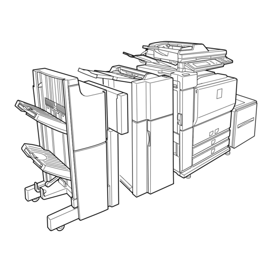
Page 28: Identification Of Each Section And Functions
MX-M700N [5] EXTERNAL VIEW AND INTERNAL STRUCTURE 1. Identification of each section and functions A. External view Finisher Parts NOTE Name Funciton/Operation Saddle stitch finisher The finisher and the saddle stitch finisher include the offset function, which offsets each Finisher set of copies from the preceding set for easy separation. - Page 29 B. Internal operation parts Parts NOTE Name Funciton/Operation Duplex unit Open the cover to remove a misfeed from the fusing/duplex unit. Fusing unit Toner images are fused here. The fusing unit is hot. Take care in removing misfed paper. Cover of the duplex unit Open when a misfeed has occurred in the duplex unit.
- Page 30 C. Operation, display parts PRINT DOCUMENT READY FILING DATA LINE IMAGE SEND DATA COPY SYSTEM JOB STATUS SETTINGS LOGOUT Parts NOTE Name Funciton/Operation Touch panel The machine status, messages and touch keys are displayed on the panel. The document filing, copy, network scanner , and fax , Internet fax functions are used...
- Page 31 D. Job status screen (common to print, copy, fax, network scan and internet fax) This screen is displayed when the [JOB STATUS] key on the operation panel is pressed. This screen can be used to display the “JOB QUEUE” (showing stored jobs and the current job) or the “COMPLETE” job list (showing finished jobs).
- Page 32 (Displayed in the touch panel) NOTE Name Function/Operation Display switching keys Use to switch the page of the displayed job list. [INTERNET-FAX] key This displays the transmission/reception status and finished jobs of Internet fax mode and PC Internet fax mode when the network scanner option is installed. [STOP/DELETE] key Use to cancel or delete the current job or delete the selected reserved job.
- Page 33 E. Sensor/detector SPED1 SPED1 STUD STUD SPLS2 SPLS2 SPPD1 SPPD1 SPLS1 SPLS1 SPWS SPWS STLD STLD SPPD3 SPPD3 SPPD2 SPPD2 SPPD4 SPPD4 SPED2 SPED2 SPOD SPOD POD3 POD3 POD2 POD2 POD1 POD1 AINPD AINPD APPD1 APPD1 MPED MPED MPLD2 MPLD2 MPLD1 MPLD1 MPFD1...
- Page 34 Connector level Signal Code Name Function/Operation Type NOTE name “L” “H” M1PED M1PED Paper empty detector Paper empty detection Transmission Paper Paper Paper feed tray (Paper feed tray 3) (Paper feed tray 3) type empty present system sensor M1PFD M1PFD Paper pass detector Paper feed tray 3 paper pass Transmission...
- Page 35 Connector level Signal Code Name Function/Operation Type NOTE name “L” “H” T2LUD T2LUD Paper feed tray upper limit Paper feed tray upper limit Transmission Upper limit – Paper feed tray detector (Paper feed tray 2) (Paper feed tray 2) type system sensor T2PED T2PED...
- Page 36 Connector level Signal Code Name Function/Operation Type NOTE name “L” “H” DSW- DSW- Duplex (ADU) cover open/ Duplex (ADU) cover open/close Transmission Duplex Duplex Door switch close detector detection type (ADU) (ADU) door door open open close DSW-DSK DSW-DSK Left door open/close Left door open/close detection Transmission Desk left...
- Page 37 Connector level Signal Code Name Function/Operation Type NOTE name “L” “H” M2SS3 M2SS3 Paper size detector Paper size detection by combination Contact Multi paper feed (Paper feed tray 4) of ON/OFF of MISS 1 – 4 switch tray vertical size detection (Refer to the separate table in the “[11] SIGNAL...
- Page 38 F. Switch DSW-L MPSW DSW-F DSW-R WH-SW Signal Code Name Type Function/Operation NOTE name MPSW MPSW Main power switch Seesaw switch Turns ON/OFF all the power sources. Power switch Seesaw switch Turns ON/OFF the main DC power source. (Turns ON/ Shut-off solenoid OFF the engine power source except for the sub DC built-in...
- Page 39 G. Clutch/solenoid SPFC SRRC STRRC SRRBC STRRBC STRC STRBC PSPS DSKLS MFPUS PSBC MPFGS T1PFC DSKPFC2 T1PUS MPFC M1PUS HPFC T2PFC M1PFC T2PUS DSKPFC1 M2PFC M2PUS Signal Code Name Function/Operation Type NOTE name Paper exit gate solenoid Paper exit gate drive Electromagnetic solenoid DSKLS...
- Page 40 Signal Code Name Function/Operation Type NOTE name STMPS STMPS Stamp solenoid control signal Stamp drive Electromagnetic solenoid STRBC STRBC DSPF paper transport roller 2 brake DSPF transport roller 2 braking Electromagnetic clutch clutch STRC STRC DSPF paper transport roller 2 clutch DSPF transport roller 2 ON/OFF control Electromagnetic clutch...
- Page 41 Signal Code Name Type Function/Operation NOTE name Scanner (reading) motor Stepping motor Drives the scanner (reading) section. Main motor DC brush-less Drives the paper feed trays 1, 2, 3, and 4, and the manual motor paper feed section. LSU motor DC brush-less Drives the scanner (writing) (LSU) unit mirror.
- Page 42 I. Lamp LEDCL CCFT Signal Code Name Type Function/Operation NOTE name CCFT CCFT LCD backlight Cold Cathode Backlight for LCD Fluorescent Tube Discharge lamp Lamp Discharges electric charges on the OPC drum. Scanner lamp Xenon lamp Radiates lights onto a document for the CCD to scan the document image.
- Page 43 J. Fan motor CFM-U1 CFM-U3 SPFFAN VFM-EX1 CFM-U4 VFM-EX2 CFM-U2 VFM-EX3 VFM-BKU VFM-BKR CFM-R1 VFM-BKL CFM-R2 CFM-HDD CFM-R3 CFM-DV CFM-ICU CFM-DC1 CFM-DC2 Signal Code Name Type Function/Operation NOTE name CFM-DC1 CFM-DC1 Power cooling fan motor DC brush-less Cools the DC power unit. motor CFM-DC2 CFM-DC2...
- Page 44 K. PWB (Main unit section) Name Function/Operation NOTE AC power PWB Controls the AC power. CCD PWB Scans document images to converts analog signal to digital signal. CIS control PWB/CIS unit Scans document images (back surface) and controls the CIS unit. DC main power PWB Generates the DC power.
- Page 45 L. FAX section Name Function/Operation MODEL NOTE MDMC PWB Controls the Modem and the TEL/LIU PWB. Modem control Fax unit FAX IF PWB • Interfaces the MDMC PWB and the main unit controller PWB. • Installs the FAX image memory. (Expansion memory can be installed.) TEL/LIU PWB •...
- Page 46 Code Name Type Specifications Function/Operation Section NOTE Fuse Time lag 250V 15A DC power source overcurrent protection DC main 100V series (Main source) power PWB Fuse Time lag 250V 3.15A Varistor overcurrent protection DC main 100V series/ power PWB 200V series Fuse Time lag 250V 5A...
- Page 47 O. Gate Name Function/Operation NOTE Switchback gate Selects the paper route when discharging paper to the inner tray and when Switched not by the solenoid drive but switching back to the exit or finisher. by the automatic procedure. Paper exit gate Selects the paper route to transport paper to the duplex (ADU) section or to Driven by the solenoid (DGS).
- Page 48 Q. Lock position Name Function/Operation NOTE Scanner lock screw Locks the scanner. (Protects the scanner unit from breakage during transit.) Be sure to lock during transit. Paper tray 1 lock block Locks the paper lift plate Paper tray 2 lock block Locks the paper lift plate Paper tray 3 lock block Locks the paper lift plate...
- Page 49 R. Roller 74 73 72 71 77 82 78 79 34 35 33 31 32 Name Function/Operation NOTE Paper feed roller Feeds paper to the paper transport section. (Manual paper feed tray) Separation roller Separates paper to prevent double-feed. (Manual paper feed tray) Paper pickup roller Sends paper to the paper transport section.
- Page 50 Name Function/Operation NOTE Separation roller Separates paper to prevent double-feed. (No. 3 paper feed tray) Paper pickup roller Sends paper to the paper transport section. (No. 3 paper feed roller) Paper feed roller Feeds paper to the paper transport section. (No.
- Page 51 Name Function/Operation NOTE Fusing roller (Heating) Heat and press toner onto paper to fuse images. Paper feed roller (DSPF) Feeds paper to the paper transport section. Separation roller (DSPF) Separates paper to prevent against double feed. Paper pickup roller (DSPF) Sends paper to the paper transport section.
-
Page 52: Adjustment Item List
MX-M700N [6] ADJUSTMENTS 1. General 2. Outline Each adjustment item in the adjustment item list is associated with a specific JOB number. Perform the adjustment procedures in the sequence of Job numbers from the smallest to the greatest. However, there is no need to perform all the adjustment items. Perform only the necessary adjustments according to the need. Unnecessary adjustments can be omitted. -
Page 53: Datails Of Adjustment
Job No Adjustment item list Simulation ADJ13 Adjusting the fusing paper guide position ADJ14 Adjusting the paper size detection ADJ14A Adjust the paper width sensor for the manual paper feed tray 40-2 ADJ14B Adjust the paper width sensor for paper feed tray 3 40-12 ADJ14C Adjust the paper width sensor for the DSPF paper feed tray... - Page 54 Adjust the developing bias voltage This adjustment is needed in the following situations: * The high voltage power PWB (MC/DV/TC) has been replaced. * U2 trouble has occurred. * The PCU PWB has been replaced. * The EEPROM of the PCU PWB has been replaced. (Main charger grid voltage adjustment) Simulation High voltage power PWB (MC/DV/TC)
- Page 55 Transfer voltage adjustment (print operation mode) Go through the modes specified in Simulation 8-17. This adjustment is needed in the following situations: * The high voltage power PWB (MC/DV/TC) has been replaced. SIMULATION 8-17 TRANSFER ROLLER SETTING. SELECT 1-3, AND PRESS START. * U2 trouble has occurred.
- Page 56 Transfer voltage adjustment (transfer roller cleaning/transfer Go through the modes specified in Simulation 8-18. roller print modes) This adjustment is needed in the following situations: SIMULATION 8-18 * The high voltage power PWB (TC cleaning) has been replaced. TRANSFER CLEANING ROLLER SETTING. SELECT 1-2, AND PRESS START.
- Page 57 Loosen the DV doctor fixing screws. On both sides of the DV doctor and at its center, make sure that the DV doctor gap is 0.525 0.03. Manually turn the DV roller to align the marking on the DV roller surface with the DV doctor position. * When inserting a clearance gauge, take care not to damage the DV doctor or MG roller.
- Page 58 Measure the distance between the marking on the DV roller Go through the modes specified in Simulation 64-1. and leading edge of the DV doctor, and make sure that it is 19 0.5mm. SIMULATION 64-1 SELF PRINT MODE. SELECT 0-7, AND PRESS START. 0.
- Page 59 Check the printed grid pattern for distortions. 11) Loosen the LSU fixing screws, and change the LSU fixing angle. [Check Method 1] * If the vertical line image is inclined to the left with respect to the Compare the front frame side and rear frame side of the front frame side, move the LSU fixing plate in arrow direction (a).
- Page 60 Manually turn the scanner drive pulley, and move Scanner Unit Without moving the scanner unit drive shaft, manually turn the B until contact with the two stoppers on the CCD mounting scanner unit drive pulley so that Scanner Unit B makes contact plate.
- Page 61 Loosen either of two fixing screws of the scanner unit drive pul- Adjust scanned image distortions in the ley. (Either one on the front or the rear side will do.) sub-scanning direction This adjustment is needed in the following situations: * The scanner (reading) section has been disassembled.
- Page 62 Check for distortions in the main scanning direction. Adjust scanned image distortions in the If the four angles of the rectangle on the copy are right angles, main scanning direction – 2 there is no distortion and therefore no further steps are This adjustment is needed in the following situations: needed.
- Page 63 Remove the document table glass, and make adjustments by Gently pulling out each check sheet for DSPF levelness turning the main scanning direction image distortion adjusting adjustment, make sure that no gap is felt between the CIS screw. guide boss and the glass for DSPF mode for each of the front and rear frame sides.
- Page 64 [Check Method 2] Adjust DSPF skews Check that the squareness of the main scanning direction print line for the longitudinal direction of paper is within 0.5mm. This adjustment is needed in the following situations: * The DSPF section has been disassembled. * The DSPF unit has been replaced.
- Page 65 Adjust by turning the DSPF skew adjusting screw on the right side of the DSPF rear frame. ADJ 5 Adjusting the image focus Remove the hexagon cap nut of the DSPF skew adjusting The result of this adjustment will affect all image scan modes (copy, screw on the right side of the DSPF hinge and loosen the fixing scan, and fax).
- Page 66 Make a normal copy on A4 paper. Slide the CCD unit in the arrow direction (CCD sub-scanning direction) to change its mounted position. Compare the copied image of the scale and the actual scale length in terms of length. 100mm scale (Original) 0.8mm Copy image...
- Page 67 Make a normal copy on A4 paper. Measure the lengths of the copied image of the scale and the actual scale. 100mm scale (Original) 0.8mm Copy image (1mm (1%) shorter Repeat the above adjustments until an acceptable result is than the original) obtained.
- Page 68 Select the number that corresponds to the adjustment item Determine the image magnification factor using the following CCD (MAIN) using the numeric keypad. formula: This adjustment items is intended to adjust the image magnifi- Image magnification factor (%) = Copy dimension/original cation in the main scanning direction in original table mode dimension x 100 (CCD).
- Page 69 Go through the modes specified in Simulation 48-1. Adjust the image magnification in the main scanning direction in DSPF front-face mode SIMULATION 48-1 MAGNIFICATION ADJUSTMENT. SELECT 0-7, AND PRESS START. (CCD) 0.TRAY SELECT 1.PRINT START This adjustment is needed in the following situations: 2.MAGNIFICATION 3.CCD(MAIN) 4.CCD(SUB)
- Page 70 Go through the modes specified in Simulation 48-1. Adjust the image magnification in the main scanning direction in DSPF back-face mode SIMULATION 48-1 MAGNIFICATION ADJUSTMENT. SELECT 0-7, AND PRESS START. (CIS) 0.TRAY SELECT 1.PRINT START This adjustment is needed in the following situations: 2.MAGNIFICATION 3.CCD(MAIN) 4.CCD(SUB)
- Page 71 Go through the modes specified in Simulation 48-1. Adjust the image magnification in the sub- scanning direction in DSPF mode SIMULATION 48-1 MAGNIFICATION ADJUSTMENT. SELECT 0-7, AND PRESS START. This adjustment is needed in the following situations: 0.TRAY SELECT 1.PRINT START * Images are not correctly magnified in the sub-scanning direction.
- Page 72 Setting Item Default range SIMULATION 48-5 TRAY Paper feed tray 1 – 6 – SCAN MOTOR SPEED ADJUSTMENT. INPUT VALUE 0-99, AND SELECT selection PRESS START. 0.MIR(220) PRINT Print start (Default) – – START (Lead edge adjustment value) Using the numeric keypad, select the number that corresponds RRCB Resist roller clutch 0 –...
- Page 73 SIMULATION 50-12 ORIGINAL OFF-CENTER ADJUSTMENT. SELECT 0-9, AND PRESS START. 0.TRAY SELECT 1.COPY START 2.MAGNIFICATION (ADJUSTMENT DATA) 3.PLATEN 4.SPF SIDE1 5.SPF SIDE2 Select other than 0 - 2, and Press [SYSTEM SETTINGS] key. press [START] key. SIMULATION 50-12 ORIGINAL OFF-CENTER ADJUSTMENT. INPUT VALUE 0-99, AND PRESS START.
- Page 74 (Scan off-center adjustment) SIMULATION 50-12 Place an original on the original table. ORIGINAL OFF-CENTER ADJUSTMENT. SELECT 0-9, AND PRESS Press the Start key. START. Check the off-center of the printed image. 0.TRAY SELECT 1.COPY START 2.MAGNIFICATION If the off-center is 0 4.0 mm, no adjustment is required. (ADJUSTMENT DATA) 3.PLATEN 4.SPF SIDE1...
- Page 75 (Scan off-center adjustment) (Adjustment mode selection) Place an original on the DSPF original tray. Go through the modes specified in Simulation 50-12. Press the Start key. Check the off-center of the printed image. If the off-center is 0 2.5 mm, no adjustment is required. SIMULATION 50-12 ORIGINAL OFF-CENTER ADJUSTMENT.
- Page 76 (Scan off-center adjustment) Place an original on the DSPF original tray. Papar lead edge Papar tail edge Press the Start key. Since the front side and back side images are copied onto sep- arate sheets, check the off-center of the back side image. No Image If the off-center is 0 2.7 mm, no adjustment is required.
- Page 77 (Trailing edge void area adjustment) Setting Item Content Default range Make a copy at 100% magnification by entering "100" into the SIDE2-ADJ Offset (adjustment) of the 1 – 99 (MAGNIFICATION) field and then pressing the Start key, and RRCB setting during rear print. check the trailing edge void area.
- Page 78 Adjust the original scan start position Adjust the copied image loss/void area in (adjust the scanner read position in DSPF- DSPF mode mode front face scan) This adjustment is needed in the following situations: This adjustment is needed in the following situations: * The MFP control PWB has been replaced.
- Page 79 Repeat the process of changing the (SIDE1 & SIDE2) adjust- ment values and then pressing the Start key until attaining an SIMULATION 50-6 acceptable level. LEAD EDGE ADJUSTMENT(SPF). (MAGNIFICATION) SIDE1: Adjustment value for the position at which to read the INPUT 25-200(%) leading edge of the original in DSPF front side mode.
- Page 80 Setting Item Default range SIMULATION 50-27 ORIGINAL IMAGE LOSS SETTING(FAX/SCN). INPUT 0-10, AND FAX send PRESS START. OC (LEAD_EDGE) OC lead edge 0 – 10 1.OC(LEAD_EDGE) (Unit 1mm) (3mm) OC (FRONT/REAR) OC side OC (TRAIL_EDGE) OC rear edge SPF (LEAD_EDGE) SPF lead edge Setting SPF (FRONT/REAR)
- Page 81 (Copied image reference density) Go through the modes specified in Simulation 46-2. Original SIMULATION 46-2 EXP. LEVEL SETUP (2). SELECT 0-6, AND PRESS START. 0. TRAY SELECT 1. COPY START 2. EXP LEVEL GRAY CHART 3. AE 3.0 4. CH 3.0 5.
- Page 82 NOTE: Adjusting the copied image density through this simulation (SIM 46-9) (Text mode) changes the copied image density settings for all copy Setting modes to the copied image density level applied by carry- Item Default range ing out this simulation. Also, the copied image density gra- TRAY SELECT Paper feed tray selection dient is automatically adjusted to the specified level.
- Page 83 Press the P or Start key. Pressing the Start key starts copy Adjust the copied image gamma in copy (print) operation as well as applying the adjustment value. mode Check the copied image gamma (copy density levels for low and high density areas) (contrast). Set the original on the original table.
- Page 84 10-A Adjust the fax mode print density for all ADJ 10 Adjusting the print quality in modes at once fax mode Set the test chart (UKOG-0162FCZZ) on the original table so that it aligns with the front frame. Then put four or five pieces of This adjustment is needed in the following situations: A3 (11"...
- Page 85 Press the P or Start key. Go through the simulation modes that correspond to the Fax modes for which to adjust the print density (i.e., the modes This applies the adjustment value. specified in Simulations 46-13, -14, -15, -16, or -45). Pressing the Start key starts print operation as well as applying the adjustment value.
- Page 86 [Binary mode] (Copied image reference density) SIMULATION 46-14 EXP.LEVEL SETUP FAX(FINE).SELECT 0-14,AND PRESS START. 0.TRAY SELECT 1.PRINT START Original 2.EXP LEVEL 3.AUTO 4.1.0 5.2.0 6.3.0 7.4.0 8.5.0 GRAY CHART 9.AUTO(H) 10.1.0(H) 11.2.0(H) 12.3.0(H) 13.4.0(H) 14.5.0(H) Select other than 0 - 2, Press [SYSTEM SETTINGS] and press [START] key.
- Page 87 Go through the modes specified in Simulation 46-21. ADJ 11 Adjusting the image quality in SIMULATION 46-21 scan mode EXP.LEVEL SETUP SCANNER(AUTO SET), PRESS START. 0.SCANNER EXP.LEVEL This adjustment is needed in the following situations: * The CCD unit has been replaced. * U2 trouble has occurred.
- Page 88 Go through the simulation modes that correspond to the scan 11-F Adjust the image gamma in scanner mode modes for which to adjust the scanned image density (i.e., the modes specified in Simulations 46-22, -23, -24, or -25). Go through the modes specified in Simulation 46-27. SIMULATION 46-21 SIMULATION 46-27 EXP.LEVEL SETUP SCANNER(AUTO SET), PRESS START.
- Page 89 – value 1: TRAY1 AE mode Image quality priority mode 2: TRAY2 (Normal mode) 3: TRAY3 * Gamma is sharp to 4: TRAY4 provide high contrast 5: Manual feed images. 6: Side LCC Toner consumption priority PRINT START Print start (Default) –...
- Page 90 ADJ 13 ADJ 14 Adjusting the fusing paper Adjusting the paper size guide position detection This adjustment is needed in the following situations: 14-A Adjust the paper width sensor for the * Paper is jammed in or around the fusing section. manual paper feed tray * Imperfect images, deformed images, or wrinkles are produced in This adjustment is needed in the following situations:...
- Page 91 Select MAX. POSITION using the numeric keypad. 14-B Adjust the paper width sensor for paper feed tray 3 This adjustment is needed in the following situations: * The paper feed tray section has been disassembled. * The paper feed tray unit has been replaced. * U2 trouble has occurred.
- Page 92 Select MIN. POSITION using the numeric keypad. Open the DSPF paper feed guide to the maximum width posi- tion. Press the Start key. The maximum width detection level is recognized. * When each of the above operations has been completed, the "COMPLETE"...
- Page 93 If any error is detected, the touch panel returns to adjustment mode. NOTE: Never use something with a sharp tip (such as a needle or pin) to press the touch panel. MX-M700N ADJUSTMENTS 6 – 42...
- Page 94 (12 V supply voltage adjustment) ADJ 17 Adjusting the supply voltage Apply a digital multi-meter to the DC sub PWB 12 V line (CN4, 1 pin) and GND (CN4, 6 pin). This adjustment is needed in the following situations: Turn RV102 on the DC sub power supply PWB so that the volt- * One or more parts of the DC main power supply unit have been age is 12 V.
-
Page 95: Adjustment Value/Simulation/Storage Data
MX-M700N [7] SIMULATION Counters Adjustment value Others ADU paper feed Toner concentration White paper exit counter temperature correction (high count setting 1. Adjustment value/Simulation and temperature side) judgment voltage storage data Staple counter Toner concentration Trouble memory temperature correction (high mode setting A. -
Page 96: Starting Simulation
2. General (3) (Data saved by the MFP control PWB) The simulation has the following functions to grasp the machine Counters Adjustment value Others operating status, identify the trouble position and causes in an ear- Copy counter FAX SOFT SW., etc. Trouble history lier stage, and make various setups and adjustments speedily for Printer counter... - Page 97 Select copy mode Press the Program key. Press the asterisk (*) key. Press the clear key. Press the Program key. Standby for entry of Press the SYSTEM SIM code. SETTINGS key Enter the main code of SIM with the 10-key. The main code of SIM is displayed.
-
Page 98: List Of Simulation Codes
3. List of simulation codes Main Data save destination/Target Operation content code code Scanner Engine Mirror scan operation Optical system sensor check SPF operation aging SPF sensor check SPF individual load check Finisher sensor check Finisher individual load check Finisher setting Inserter sensor check Inserter load operation Inserter tray value setting... - Page 99 Main Data save destination/Target Operation content code code Scanner Engine JAM/Trouble counter data clear Paper feed counter clear ORG/Staple counter clear Maintenance counter data clear Developer counter data clear Copy counter data clear Drum/Toner counter data clear Printer/Other counter data clear FAX counter data clear Various rotation time timer clear Network scanner counter data clear...
- Page 100 Main Data save destination/Target Operation content code code Scanner Engine Magnification ratio adjustment (by Input/Output) Motor speed adjustment Firmware update Copy lead edge adjustment (Document table) Lead edge adjustment (Document table simple type) Print lead edge adjustment Copy lead edge adjustment (SPF) Copy lead edge adjustment (SPF simple type) Print off-center adjustment Document off-center adjustment...
- Page 101 Main Data save destination/Target Operation content code code Scanner Engine FAX-related soft SW setting check/change FAX-related soft SW clear (Excluding FAX adjustment values) FAX-related memory check Signal send mode (Signal send level: Max.) Signal send mode (Signal send level: Soft SW setting) Confidential pass code print Image memory content output Voice message reproduction (Signal send level: Max.)
-
Page 102: Details Of Simulation
4. Details of simulation The operation can be stopped with the [SYSTEM SETTINGS] key. HIGH SPEED (220mm/sec) High speed LOW SPEED (110mm/sec) Low speed TOP SPEED (360mm/sec) Top speed SIMULATION 2-1 Purpose Operation test/Check SPF AGING TEST. SELECT 1-3, AND PRESS START. Function (Purpose) Used to check the operations of the scan- 1. - Page 103 PI11S Saddle paper exit detection When the saddle unit is MOTOR (T) Motor top speed installed MOTOR (H) Motor high speed PI12 Tray 2 paper detection MOTOR (L) Motor low speed PI12S Semi-circular roller phase detection When the saddle unit is STRBC Document transport brake clutch installed...
- Page 104 Item Setting range Staple binding position 68 - 132, 1STEP: 0.152 mm Purpose Operation test/Check adjustment Function (Purpose) Used to check the operation of the load in Punch center 37 - 63, 1STEP: 0.15mm adjustment the finisher and the control circuit. Punch hole position 35 - 57, 1STEP: 0.26mm Section...
- Page 105 <LCC> 3-31 Transport sensor Purpose Operation test/Check Tray upper limit sensor Function (Purpose) Used to check the operations of the loads Tray lower limit sensor in the inserter and the related circuits. LPED Tray paper presence/empty sensor Section Inserter LTOD Main unit connection detection sensor Tray insertion detection Operation/Procedure...
- Page 106 Purpose Operation test/Check Function (Purpose) Used to check the operation of the heater lamp and the control circuit. Purpose Operation test/Check Section Fusing/Paper exit Function (Purpose) Used to check the operation of the paper Operation/Procedure transport system loads (clutch, solenoid) Select the number corresponding to the target of operation and the control circuit.
- Page 107 Purpose Operation test/Check Function (Purpose) Used to check the operations of each fan motor and its control circuit. Purpose Setting Section Others Function (Purpose) Used to set the operating conditions of Operation/Procedure aging. Select the number corresponding to the target of operation Section —...
- Page 108 Setting Item Default range Purpose Setting AUTO Auto mode 0 - 750 Function (Purpose) Used to set the intermittent aging cycle. CHARACTER Text mode Text/Photo mode Section — PHOTO Photo mode Operation/Procedure PRINTER Printer mode Enter the intermittent aging cycle (unit: sec) with 10-key. FAX mode Press [START] key.
- Page 109 : '07 Feb 15 The operation can be stopped with the [SYSTEM SETTINGS] key. The operation can be stopped with the [SYSTEM SETTINGS] key. (The transfer output voltage adjustment and output check can be (The output voltage of the transfer CL roller cleaning/transfer CL made in each print mode.) roller print mode can be adjusted and checked.) Default...
- Page 110 10-2 Purpose Operation test/Check Purpose Operation test/Check Function (Purpose) Used to check the operations of the sen- Function (Purpose) Used to check the operations of the toner sors and detectors in the duplex section remaining quantity sensor and the related and its control circuit.
- Page 111 SIMULATION 14 TROUBLE CANCELLATION. (OTHERS) ARE YOU SURE? 1. YES 17-0 2. NO Purpose Clear/Cancel (Trouble etc.) Function (Purpose) Used to cancel the PF troubles (when the copy inhibit command from the host com- puter is received). Section Communication unit (RIC/MODEM etc.) 15-0 Operation/Procedure...
- Page 112 22-3 Purpose Adjustment/Setup/Operation data output/ Check (Display/Print) 22-1 Function (Purpose) Used to check misfeed positions and the misfeed count of each position. (If the mis- Purpose Adjustment/Setup/Operation data output/ feed count is considerably great, it may be Check (Display/Print) judged as necessary to repair.) Function (Purpose) Used to check the print count value in each Section Sections other than DSPF section...
- Page 113 Code Description M2PFD_S M2PFD remaining jam SIMULATION 22-3 PAPER JAM HISTORY. MPRD2_N2 MPRD2 not-reached jam (Tray 2 feed paper) ** ** * ** ,* ** ** ** ,* ** ** ** , ** ** ** *, ** ** ** *, ** ** * ** ,* ** ** ** ,* ** ** ** ,* * ** ** *,******* MPRD2_NM MPRD2 not reached jam ** ** * ** ,* ** ** ** ,* ** ** ** , ** ** ** *, ** ** ** *, ** ** * ** ,* ** ** ** ,* ** ** ** ,* * ** ** *,*******...
- Page 114 22-6 SIMULATION 22-8 Purpose Adjustment/Setup/Operation data output/ ORG./STAPLE COUNTER DATA DISPLAY. Check (Display/Print) SPF: ******** Function (Purpose) Used to output the list of the setting and SCAN: ******** adjustment data (simulations, FAX soft STAPLER: ******** PUNCH: ******** STAMP: ******** SADDLE STAPLER: ******** switch, counters).
- Page 115 (Model code list) 22-11 Item Display Content Purpose Adjustment/Setup/Operation data output MACHINE (Model code) Network optional model /Check (Display/Print) (55 ppm) Function (Purpose) Used to check the use frequency (send/ (Model code) Network optional model receive) of FAX. (Only when FAX is (62 ppm) installed) (Model code)
- Page 116 22-13 22-30 Purpose Adjustment/Setup/Operation data output/ Purpose Setting value display/Check Check (Display/Print) Function (Purpose) OSA vendor ID display (Application Com- Function (Purpose) Used to check the operating time of the munication Module) process section (OPC drum, DV unit, toner Section —...
- Page 117 SIMULATION 23-2 JAM/TROUBLE DATA PRINT MODE SELECT SETTING, AND PRESS START. 0. TRAY SELECT AUTO ONLY 24-1 1. PRINT START Purpose Data clear Function (Purpose) Used to clear the misfeed counter, the mis- feed history, the trouble counter, and the 23-80 trouble history.
- Page 118 24-5 24-3 Purpose Data clear Purpose Data clear Function (Purpose) Used to reset the developer counter. Function (Purpose) Used to clear the number of use of the fin- (The developer counter of the DV unit isher, SPF, and the scan (reading) unit. which is installed is reset.) Section —...
- Page 119 After replacing the OPC drum, be sure to clear the OPC drum 24-11 counter. Purpose Data clear DRUM OPC drum counter Function (Purpose) Used to reset the OPC drum rotation time, and the DV unit rotation time counter. The developer counter in the DV unit installed is SIMULATION 24-7 DRUM COUNTER DATA CLEAR.
- Page 120 SIMULATION 24-15 SIMULATION 25-2 NETWORK SCANNER AND INTERNET-FAX COUNTER CLEAR. AUTOMATIC DV ADJUSTMENT. PRESS START. SELECT1-12, AND PRESS START. HUMIDITY AREA : 70.0 72.5 1. NETWORK SCANNER ORIGINAL COUNTER DEVE REFERENCE : 2. MAIL COUNTER 3. FTP COUNTER 4. INTERNET-FAX ORIGINAL COUNTER: ******** 5.
- Page 121 SIMULATION 26-3 SIMULATION 26-6 AUDITOR SETUP. SELECT 1-3, AND PRESS START. DESTINATION SETUP. SELECT 1-10, AND PRESS START. 1. P10 1.USA 2.CANADA 3.INCH 2. VENDOR 4.JAPAN 5.AB_B 3. OTHERS 6.EUROPE 7.UK 8.AUSTRALIA 4. VENDOR-EX 9.AB_A 10.CHINA 5. VENDOR-EX + 6. VENDOR-EX (MULTI JOB) 7.
- Page 122 : '07 Feb 15 26-30 26-38 Purpose Setting Purpose Setting Function (Purpose) Used to set the operation mode conforming Function (Purpose) Used to set CONTINUE/STOP of printing to the CE mark (Europe safety standards). when maintenance timing is over and the (Conforming to soft start when driving the count value reaches 110% of replacement fusing heater lamp.)
- Page 123 26-52 Purpose Setting Function (Purpose) Used to set whether non-print paper (inser- 27-1 tion paper, cover paper) (blank image print Purpose Setting paper) is counted up or not. Function (Purpose) Used to set the specifications for opera- Section Paper transport tions in case of communication trouble (Paper exit/Switchback/Transport) between the host computer and MODEM...
- Page 124 M1PED Tray 3 paper empty M1SS1 Tray 3 rear edge detection switch 1 M1SS2 Tray 3 rear edge M1SS3 Tray 3 rear edge switch 2 switch 3 30-1 M1SS4 Tray 3 rear edge M1SPD Tray 3 paper switch 4 remaining quantity Purpose Operation test/Check detection...
- Page 125 40-11 40-2 Purpose Operation test/Check Purpose Adjustment Function (Purpose) Used to check the multi-purpose tray width Function (Purpose) Used to adjust the manual paper feed tray detection adjustment value. paper width detector detection level. Section Paper feed Section Paper feed Operation/Procedure Operation/Procedure The sensor and detector operation conditions are displayed.
- Page 126 : '07 Feb 15 41-3 Purpose Operation test/Check Function (Purpose) Used to check the operation of the docu- 41-1 ment size sensor and the related circuit. Purpose Operation test/Check (The document size sensor output level can be monitored with the LCD display.) Function (Purpose) Used to check the operation of the docu- ment size sensor and the related circuit.
- Page 127 10-key. DMLED Drum marking sensor gain adjustment value Press the [START] key. PCLED Image density sensor gain adjustment value DRUM Kind of the drum 0 = Other/1 = SHARP drum Item Default BIT1 OPC drum membrane Laser power/main decrease (sensitivity/...
- Page 128 : '07 Feb 15 Item NOTE 44-4 DEVE MIXING Developing roller rotation Reset by SIM 24-11. TIME time (sec) Purpose Setting DRUM OPC drum identification 1: 55/62 (ppm) Function (Purpose) Used to set the target density level in the code 0: 70 (ppm) image density correction.
- Page 129 SIMULATION 44-12 SIMULATION 44-16 DM DATA, PATCH/BASE DATA DISPLAY. TONER CONTROL STANDARD LEVEL DISPLAY. DMLED: PC LED: END DV_BS: HUMIDITY AREA: PT1/BS1 PT2/BS2 PT3/BS3 INT HUMIDITY AREA: ID(1): 000/000 000/000 000/000 TARGET LEVEL = DEV REF + HUM(TARGET) + A + B ID(2): 000/000 000/000...
- Page 130 NOTE: When [P] key is pressed after entering an adjustment value Enter the number corresponding to the paper feed tray to be in this simulation, the adjustment value is set. When used with 10-key. [START] key is pressed, the adjustment value is set and Press [START] key.
- Page 131 Press [START] key. (The paper feed tray is selected.) TRAY1 TRAY1 TRAY2 TRAY2 TRAY1 TRAY1 TRAY3 TRAY3 TRAY2 TRAY2 TRAY4 TRAY4 TRAY3 TRAY3 Manual paper feed TRAY4 TRAY4 Side LCC Manual paper feed Side LCC NOTE: When [P] key is pressed after entering an adjustment value in this simulation, the adjustment value is set.
- Page 132 NOTE: When [P] key is pressed after entering an adjustment value NOTE: When [P] key is pressed after entering an adjustment value in this simulation, the adjustment value is set. When in this simulation, the adjustment value is set. When [START] key is pressed, the adjustment value is set and [START] key is pressed, the adjustment value is set and copying is performed.
- Page 133 Enter the number corresponding to the paper feed tray to be When [START] key is pressed, printing is performed and the used with 10-key. adjustment value is set simultaneously. Press [START] key. (The paper feed tray is selected.) Check the density of print image. TRAY1 TRAY1 Normal display...
- Page 134 NOTE: When [P] key is pressed after entering an adjustment value 46-16 in this simulation, the adjustment value is set. When [START] key is pressed, the adjustment value is set and Purpose Adjustment copying is performed. Function (Purpose) Used to adjust the print density in the FAX mode (each ultra fine mode).
- Page 135 (Gamma adjustment) 46-18 After completion of the above procedures, perform the following procedures. Purpose Adjustment Enter the gamma level with 10-key. Function (Purpose) Used to adjust the gamma (density gradi- ent) in the copy mode. Press the [P] or [START] key. When [START] key is pressed, printing is performed and the Section —...
- Page 136 — — (Normal mode) * Gamma is EXP LEVEL Exposure level — — sharp to provide high contrast selection images. 3: Exposure level 1.0 Toner consumption priority 4: Exposure level 1.5 mode * Gamma is mild to 5: Exposure level 2.0 provide low contrast images.
- Page 137 NOTE: Only the set value is changed and no printing is performed. Setting Item Default range SIMULATION 46-21 AUTO Auto 0 - 99 EXP.LEVEL SETUP SCANNER(AUTO SET), PRESS START. Exposure level 1 0.SCANNER EXP.LEVEL Exposure level 2 Exposure level 3 Exposure level 4 Exposure level 5 AUTO (H)
- Page 138 46-27 SIMULATION 46-24 Purpose Adjustment EXP.LEVEL SETUP SCANNER(SUPER FINE). SELECT 0-11,AND PRESS START. Function (Purpose) Used to adjust the gamma (density gradi- 0.AUTO 1.1.0 2.2.0 ent) of the network scanner mode. 3.3.0 4.4.0 5.5.0 Section — 6.AUTO(H) 7.1.0(H) 8.2.0(H) 9.3.0(H) 10.4.0(H) 11.5.0(H) Operation/Procedure...
- Page 139 : '07 Feb 15 Setting 46-45 Item Default range Purpose Adjustment OC_AE AE mode (OC) 1 - 5 Function (Purpose) Used to adjust the image density in the FAX OC_CHARA Text mode (OC) mode (600dpi). OC_MIX Text/Photo mode (OC) OC_PHOTO Photo mode (OC) Section —...
- Page 140 TRAY1 TRAY1 TRAY2 TRAY2 TRAY3 TRAY3 TRAY4 TRAY4 48-1 Manual paper feed Purpose Adjustment Side LCC Function (Purpose) Used to adjust the copy magnification ratio When the total of the above set value (1 - 6) and 10 is entered, the (in the main scanning and the sub scanning mode is changed to the duplex mode.
- Page 141 The input value is saved by pressing the [START] key * Set LEAD to 15. (Enter 15 as the adjustment value of LEAD, and press [P] key.) (0.1mm/step) * Set DENA to 35. (Enter 35 as the adjustment value of SIMULATION 48-5 DENA, and press [P] key.) (0.1mm/step) MOTOR SPEED ADJUSTMENT.
- Page 142 Make a copy at 400%, and calculate the values of L1 and L2. Normal display NOW COPYING. (Enter 100 as the set value (MAGNIFICATION) of the copy ERROR display Door open DOOR OPEN. magnification ratio, and press [START] key.) (Place a scale on the document table and make a copy.) Paper empty PAPER EMPTY.
- Page 143 : '07 Feb 15 (Copy condition setting in this simulation) If an acceptable result is not obtained, do the following steps. To select paper (paper feed tray), perform the following procedures. * If the leading edge void area is not 3.5 mm: Enter 0 with 10-key.
- Page 144 : '07 Feb 15 Change the adjustment values of SIDE1 and SIDE2, and per- Default Setting form the adjustment. (Change the adjustment values of SIDE1 Item 55/62 range and SIDE2, and press [START] key.) (ppm) (ppm) TRAY 4 Tray 4 adjustment SIDE1: SPF front surface document lead edge scan position Manual feed tray adjustment value...
- Page 145 Set the adjustment value of L5 to 0. (Enter 0 as the adjustment Setting Item Default value of L5, and press [P] key.) range (Image loss set value: SIDE 1) Make a copy at 200% with the SPF, and calculate the values of LEAD_EDGE Front surface lead 0 - 99...
- Page 146 Setting Setting Item Default Item Default range range LEAD_EDGE Front surface lead 0 - 99 TRAY1 Tray 1 adjustment 0 - 99 edge image loss set TRAY2 Tray 2 adjustment value TRAY3 Tray 3 adjustment FRONT_REAR Front surface side TRAY4 Tray 4 adjustment edge image loss set Manual feed tray...
- Page 147 Enter 2 with 10-key. 50-12 Press the [START] key. Purpose Adjustment Enter the copy magnification ratio with 10-key. Function (Purpose) Used to adjust the scan image off-center position. (Adjusted separately for each Setting range 25 - 400 (%) scan mode.) Press the [START] key.
- Page 148 : '07 Feb 15 Default Setting Setting Item 55/62 Item Default range range (ppm) (ppm) Scanner mode TRAY1 Tray 1 resist 0 - 99 OC lead edge 0 - 10 adjustment value (LEAD_EDGE) (Unit (0mm) TRAY2 Tray 2 resist 1mm) OC (FRONT/ OC side adjustment value...
- Page 149 53-7 SIMULATION 51-2 Purpose Adjustment/Setup/Operation data output/ RESIST TIMING ADJUSTMENT. SELECT 0-14, AND PRESS START. Check (Display/Print) 0.TRAY SELECT 1.PRINT START 2.TRAY1 3.TRAY2 4.TRAY3 Function (Purpose) Used to enter the SPF width detection 5.TRAY4 6.BPT 7.LCC adjustment value. 8.ADU 9.SPF(TOP) 10.SPF(HIGH) Section DSPF...
- Page 150 55-1 56-1 Purpose Setting Purpose Data transfer Function (Purpose) Used to set the specifications of the engine Function (Purpose) Used to transfer the MFP controller data. control operations. (PCU PWB) (Used to repair the PWB.) Section — Section MFP controller Operation/Procedure Operation/Procedure This simulation is used to change and check the engine soft SW.
- Page 151 : '07 Feb 15 Default Setting Item 55/62 range (ppm) (ppm) Auto exposure mode 32 - 82 60-1 CHARA. Text mode Purpose Operation test/Check Text/Photo mode Function (Purpose) Used to check the MFP control (DRAM) PHOTO Photo mode operations (read/write). Press the [START] key.
- Page 152 SIMULATION 62-3 HDD R/W TEST(ALL). ARE YOU SURE? 62-1 1. YES Purpose Data clear 2. NO Function (Purpose) Used to format the hard disk. Section MFP controller (HDD) Operation/Procedure 62-6 Select YES/NO of hard disk format. Purpose Operation test/Check Function (Purpose) Used to check the operations of the hard Execution disk.
- Page 153 62-11 62-8 Purpose Data clear Purpose Data clear Function (Purpose) Used to delete document filing data. Function (Purpose) Used to format the hard disk (the system (The management area (standard folder, area excluded). user folder) is cleared.) Section MFP controller (HDD) Section MFP controller (HDD) Operation/Procedure...
- Page 154 Press the [START] key. 63-2 (Print condition setting in this simulation) Purpose Adjustment * To select paper (paper feed tray), perform the following proce- Function (Purpose) Used to execute shading. dures. Section Optical (Image scanning) Select TRAY SELECT with 10-key. Operation/Procedure Press [START] key.
- Page 155 (Note 1) Print pattern ENGINE CONTROLLER PATTERN NOTE PATTERN PATTERN ENGINE CONTROLLER All surface 1 by 4 PATTERN NOTE PATTERN PATTERN (Horizontal) For off-center All surface 1 by 5 adjustment (Vertical) Main scanning All surface 1 by 5 direction 1 by 5 (Horizontal) Main scanning All surface 2 by 2...
- Page 156 Enter the number corresponding to the bit to be changed with 10-key. (Example) When the bit of 5 is to be changed, enter 5. The set value of 1/0 is alternatively changed every time when 65-1 the target key is pressed. Purpose Adjustment After completion of setting of all the bits, press [START] key.
- Page 157 NOSIGNAL No signal 12.0 V33 12.0 V33 66-3 33.6 V34 26.4 V34 14.4 V17 14.4 V17 Purpose Operation test/Check 31.2 V34 31.2 V34 12.0 V17 12.0 V17 Function (Purpose) Used to check the operation of the FAX 28.8 V34 28.8 V34 9.6 V17 9.6 V17 PWB memory (read/write).
- Page 158 NONE Mute MESSAGE9 Message 9 SIMULATION 66-5 PAUSE Pause sound MESSAGE10 Message 10 SIGNAL OUTPUT CHECK.(SOFT SW.) SELECT 1-32, AND PRESS MESSAGE1 Message 1 MESSAGE11 Message 11 START. MESSAGE2 Message 2 MESSAGE12 Message 12 1.NOSIGNAL 2.33.6 V34 3.31.2 V34 4.28.8 V34 MESSAGE3 Message 3 MESSAGE13...
- Page 159 66-10 NO SIGNAL No signal 00000 00000 11111 11111 010101 010101 Purpose User data output/Check (Display/Print) 11110 11110 00001 00001 Function (Purpose) Used to clear all data of the image memory When the number is entered during execution, the kind of signal (memory send/receive).
- Page 160 : '07 Feb 15 When [SYSTEM SETTINGS] key is pressed during execution, the operation is stopped. SIMULATION 66-14 DIAL TEST(10PPS). SELECT 0-1, AND PRESS START. 0. EXECUTE SIMULATION 66-16 1. MAKE TIME ; [+29 ms] DIAL TEST(DTMF). SELECT 0-2, AND PRESS START. 0.
- Page 161 Press [START] key. This function is valid only when the FAX expansion memory is SIMULATION 66-21 installed. FAX INFORMATION PRINT OUT. SELECT 1-5, AND PRESS START. Backup contents 1. REGISTERED 2. MANAGEMENT 3. FILE MANAGEMENT 4. SYSTEM ERROR • One-touch dial •...
- Page 162 66-24 66-27 Purpose Clear Purpose Setting Function (Purpose) Used to clear the FAST memory data. Function (Purpose) Used to register the transfer number for voice warp. (Only when FAX is installed) Section Not used in the market. (For development) Operation/Procedure Section Select YES/NO of data clear.
- Page 163 66-30 66-33 Purpose Operation test/Check Purpose Operation test/Check Function (Purpose) Used to check the change in the TEL/LIU Function (Purpose) Used to check the signal (BUSY TONE/ status. CNG/CED/FNET/DTMF) detection. Section Section Operation/Procedure Operation/Procedure The TEL/LIU state is displayed. The detected signal is highlighted. When the state is changed, it is highlighted.
- Page 164 66-36 66-42 Purpose Operation test/Check Purpose Setting Function (Purpose) Used to check interface between MFPC Function (Purpose) Reloads the PIC program installed to FAX controller and MDMC. (Check of the data BOX. line or the command line) Section Section Operation/Procedure Operation/Procedure NOTE: Before processing, permit writing to the FAX PROGRAMA.
- Page 165 66-60 Purpose Setting Function (Purpose) Used to set the ACR data. Section Operation/Procedure Enter the number corresponding to the set item with 10-key. The item list menu can be switched by pressing [P] key. Press [START] key. Enter the setting value with 10-key. Press [START] key.
-
Page 166: Self Diag
MX-M700N [8] SELF DIAG AND TROUBLE CODE 1. Self diag Monitors the machine When a trouble occurs in the machine or when the life of a consum- conditions. able part is nearly expired or when the life is expired, the machine detects and displays it on the display section. - Page 167 D. Breakdown sequence (1) Breakdown mode list There are following cases of the breakdown mode. Operation enable mode Judgment Copy read Notification kind of trouble Trouble code Email List block (including Print send receive print print interrupt) FASThost (DSPF breakdown) Scanner ✕...
- Page 168 • Trouble mode process The machine can be operated under some conditions. Operations except for the trouble mode are enabled (READY). For the modes which cannot be operated, only setting is enabled and a mes- sage is given to show the operations are disabled. (NOT READY in this case) (Display) When a trouble occurs, a dialog is shown.
-
Page 169: Trouble Code List
2. Trouble code list Trouble code Trouble Trouble content Mechanism Option Electricity Supply detection Main code code MC trouble Another communication error occurs. Network The network card is not installed or broken. Network The specified mail server or the FTP server is not found. Network The specified server suspends response during transmission of Network... - Page 170 Trouble code Trouble Trouble content Mechanism Option Electricity Supply detection Main code code Process control trouble (Photoconductor surface reflection rate abnormality) Process control trouble (Drum marking scan trouble) Drum marking sensor gain adjustment error Process thermistor breakdown Developing thermistor breakdown Room temperature thermistor breakdown Developing humidity sensor break down Machine tray 1 lift-up trouble...
-
Page 171: Details Of Trouble Code
3. Details of trouble code CE-03 The specified server suspends response during transmission of C1-00 MC trouble images. Details Three successive MHV-T signals are detected during operation of MHV. Details The specified server suspends response during transmission of images. Main charger output abnormality (Output open) A trouble signal is outputted from the high voltage Section transformer. -
Page 172: Hdd Trouble
CE-07 The entered account name of the E7-01 System data trouble POP3 server or the password for authentication is invalid. Details While reading/writing the HDD system area data, the HDD returns an error response or no response at all for longer than 30 seconds. Details POP3 server authentication check error Section... - Page 173 E7-06 Decode error trouble E7-12 CCD shading trouble (White correction center adjustment) Details A decode error occurs in making an image. Section Controller Details The CCD white reference plate scan level Case 1 Cause Garbled data in input from PCI to PM DM trouble abnormality when lighting the copy lamp Data are garbled in image compression/transfer.
- Page 174 E7-56 Incompatibility check (62ppm) E7-80 Communication trouble between the (Engine (PCU) detection) MFP control and the scanner (MFP control detection) Details An error is detected in the internal incompatibility check in the engine (PCU). Details Communication establishment error/ framing/ Section Engine (PCU) parity/ protocol error.
- Page 175 EE-EU Auto developer adjustment trouble F1-03 Finisher oscillation motor trouble (Undertoner error) Details When opening the oscillation unit, the opening process is not completed in 1sec. Details Described on the toner density control design When closing the oscillation unit, the closing specifications and the change request.
- Page 176 F1-11 Finisher/pusher motor trouble F1-32 Finisher-saddle communication trouble Details When learning the paper exit roller speed, the process is not completed in 10sec. Details Communication error between the finisher and the When controlling the paper exit roller speed, an saddle encoder input is not detected in a specified time.
- Page 177 F1-38 Finisher/punch backup ROM trouble F1-45 Finisher/saddle front staple motor trouble Details Punch unit backup RAM data are garbled. Section Finisher Details The home position sensor does not turn off within Case 1 Cause Punch control PWB trouble the specified time after normal starting of the Malfunction caused by noises motor.
- Page 178 F1-60 Finisher-inserter communication F2-02 Toner supply abnormality trouble Details Toner remains in the toner bottle when undertoner is detected by the toner concentration sensor in Details Finisher/inserter communication trouble the developing unit. Section Inserter Section Engine Case 1 Cause Improper connection or disconnection of the Case 1 Cause Toner concentration sensor trouble.
- Page 179 F2-32 Process control trouble F2-46 Developing thermistor breakdown (Drum marking scan trouble) Details When the input value of the process thermistor is detected as 244 or greater or 20 or smaller for 3 Details The drum marking size, density, or the number of times continuously units is improper.
- Page 180 F3-12 Machine tray 1 lift-up trouble F3-42 Machine tray 4 lift-up trouble Details PED does not turn on within the specified time. Details MCPED does not turn on within the specified time. LUD does not turn on within the specified time. MCLUD does not turn on within the specified time.
- Page 181 F6-04 FAX modem operation abnormality F6-98 Combination error of the FAX-BOX destination information and the machine destination information Details The initializing process of the modem chip in the FAX PWB is not completed normally. Section Details When the destination information stored in the Case 1 Cause SW101 in the FAX PWB tries to perform normal...
- Page 182 H2-02 Thermistor open/Fusing unit not H3-02 Fusing section high temperature installed (HL3) trouble (HL3) Details Thermistor open Details The fusing temperature exceeds 241.5 °C. (An input voltage of 4.6V or above is detected.) (An input voltage of 1.3V or less is detected.) Fusing unit not installed When fusing temperature control is started and a temperature of 242 °C is detected 3 times...
-
Page 183: Scanner Feed Trouble
H4-01 Fusing section low temperature H5-01 5-times continuous POD notreached trouble (HL2) JAM detection Details The set temperature is not reached within the Details When POD1 not-reached jam is detected 5-times specified time (normally 3 min or 5 min in the curl continuously. - Page 184 L4-02 Drum motor lock detection L4-30 Controller fan motor lock detection Details The motor lock signal is detected for 1.5sec during Details The motor lock signal is detected during rotation of rotation of the drum motor. the controller fan motor. When the motor lock signal is detected for 3 times The motor lock signal is detected during rotation of continuously in the interval of 500ms after 900ms...
- Page 185 PF-00 RIC copy inhibit command receive U2-11 Counter check sum error (MFP control) Details The copy inhibit command is received from the RIC (host). (By PPC communication standards.) Details EEPROM counter area checksum error. Section Controller (If this error occurs, the process will retrieve for Case 1 Cause Judged by the host.
- Page 186 U2-23 SRAM memory individual data check U2-81 Memory check sum error (Scanner) sum error Details When counter data sum error is detected. Section Scanner Details Check sum error for every individual data in SRAM Case 1 Cause EEPROM trouble of the MFPC section when turning on the power Check and Check that the EEPROM is properly installed.
- Page 187 U5-31 DSPF tray lift-down trouble U6-22 LCC 24V power abnormality addition Details STLD does not turn off within the specified time. Details 24V power is not supplied to the LCC. (The LCC 24V power is not detected for 1 sec or Section Scanner longer after 1 sec from power on)
-
Page 188: Maintenance System Table
[9] MAINTENANCE MX-M700N 1. Maintenance system table ✕ : Check ▲: Replace ✩: Lubricate : Clean : Adjust : Shift position (Clean, replace, or adjust as necessary.) 1000 1250 1500 1750 2000 Remark/Refer to the 55ppm (PM: 250K) Parts Guide. When Block/Item No. - Page 189 1000 1250 1500 1750 2000 Remark/Refer to the 55ppm (PM: 250K) Parts Guide. When Block/Item No. calling (Only the replacement 1200 1500 1800 2100 2400 62ppm/70ppm (PM: 300K) parts are described.) Unit name Part name ✕ Transport section/ PS follower roller ✕...
- Page 190 1000 1250 1500 1750 2000 Remark/Refer to the 55ppm (PM: 250K) Parts Guide. When Block/Item No. calling (Only the replacement 1200 1500 1800 2100 2400 62ppm/70ppm (PM: 300K) parts are described.) Unit name Part name ✕ Side Paper feed Paper pickup roller/ (Note 2) separation Paper feed rollers...
-
Page 191: Details Of Maintenance
2. Details of maintenance A. Drum peripheral section ✕ : Check ▲: Replace ✩: Lubricate : Clean : Adjust : Shift position (Clean, replace, or adjust as necessary.) 1000 1250 1500 1750 2000 Remark/Refer to the 55ppm (PM: 250K) Parts Guide. When Block/Item No. - Page 192 B. Transfer section ✕ : Check ▲: Replace ✩: Lubricate : Clean : Adjust : Shift position (Clean, replace, or adjust as necessary.) 1000 1250 1500 1750 2000 Remark/Refer to the 55ppm (PM: 250K) Parts Guide. When Block/Item No. calling (Only the replacement 1200 1500...
- Page 193 C. Developing section ✕ : Check ▲: Replace ✩: Lubricate : Clean : Adjust : Shift position (Clean, replace, or adjust as necessary.) 1000 1250 1500 1750 2000 Remark/Refer to the 55ppm (PM: 250K) Parts Guide. When Block/Item No. calling (Only the replacement 1200 1500...
- Page 194 D. Fusing unit ✕ : Check ▲: Replace ✩: Lubricate : Clean : Adjust : Shift position (Clean, replace, or adjust as necessary.) 1000 1250 1500 1750 2000 Remark/Refer to the 55ppm (PM: 250K) Parts Guide. When Block/Item No. calling (Only the replacement 1200 1500...
- Page 195 E. Scanner section ✕ : Check ▲: Replace ✩: Lubricate : Clean : Adjust : Shift position (Clean, replace, or adjust as necessary.) 1000 1250 1500 1750 2000 Remark/Refer to the 55ppm (PM: 250K) Parts Guide. When Block/Item No. calling (Only the replacement 1200 1500...
- Page 196 F. DSPF section ✕ : Check ▲: Replace ✩: Lubricate : Clean : Adjust : Shift position (Clean, replace, or adjust as necessary.) 1000 1250 1500 1750 2000 Remark/Refer to the 55ppm (PM: 250K) Parts Guide. When Block/Item No. calling (Only the replacement 1200 1500...
- Page 197 G. Paper feed section ✕ : Check ▲: Replace ✩: Lubricate : Clean : Adjust : Shift position (Clean, replace, or adjust as necessary.) 1000 1250 1500 1750 2000 Remark/Refer to the 55ppm (PM: 250K) Parts Guide. When Block/Item No. calling (Only the replacement 1200...
- Page 198 H. Transport section/paper exit reverse section/duplex section ✕ : Check ▲: Replace ✩: Lubricate : Clean : Adjust : Shift position (Clean, replace, or adjust as necessary.) 1000 1250 1500 1750 2000 Remark/Refer to the 55ppm (PM: 250K) Parts Guide. When Block/Item No.
- Page 199 I. Drive section ✕ : Check ▲: Replace ✩: Lubricate : Clean : Adjust : Shift position (Clean, replace, or adjust as necessary.) 1000 1250 1500 1750 2000 Remark/Refer to the 55ppm (PM: 250K) Parts Guide. When Block/Item No. calling (Only the replacement 1200 1500...
-
Page 200: Other Related Items
J. Filters ✕ : Check ▲: Replace ✩: Lubricate : Clean : Adjust : Shift position (Clean, replace, or adjust as necessary.) 1000 1250 1500 1750 2000 Remark/Refer to the 55ppm (PM: 250K) Parts Guide. When Block/Item No. calling (Only the replacement 1200 1500 1800... - Page 201 C. Execution items after maintenance and servicing Item Simulation The paper jam/trouble data are cleared. The use quantity counter of each paper feed section is cleared. The numbers of use of the DSPF, the scanner, the finisher, the inserter, the stapler, and the punch are cleared. The maintenance counter is cleared.
-
Page 202: Rom Version-Up
MX-M700N [10] ROM VERSION-UP 1. General A. Version-up target ROM's The version-up target ROM's are listed in the table below. [Kind of ROM] The version-up procedures of the firmware of this machine is per- Section Name Type Capacity Replaceable formed without disassembling the ROM from the machine. The new PCU PWB PCU ROM Flash... -
Page 203: Flash Rom Version-Up Method
2. Precautions 3. Necessary items for Flash ROM version-up A. Relationship between each ROM and version-up • A machine with ROM to be operated When performing ROM version-up, be sure to check the combina- • A spare PCU PWB ROM, an MFP control PWB ROM (Boot, Pro- tion with the version of ROM installed in the other PWB's including gram), a scanner control PWB ROM (Each of which is provided optional ones. - Page 204 B. Version-up procedure 2 When writing the program files collectively without disassembling the ROM's from the PWB's, and when writing the program files into NOTE1: MFP control PWB ROM DIP switch selection and Flash an optional ROM: ROM slot NOTE: The PCU ROM, the FAX ROM, and the scanner control To make version-up of the ROM, position of the DIP switch should PWB ROM must be provided with the program to operate.
-
Page 205: Writing Data
When "Result: OK" is displayed after a few minutes, press Up/ Press MENU key a few times to show the following display. Down keys to check that there is no display of "Result: NG." * When writing the program file data collectively to the CN Update machine without the FAX unit installed, "Result : NG"... - Page 206 5. Turning OFF the power during the 12) "CN5" and the selection menu of slot numbers is displayed. Select "CN6" to which the target ROM is inserted to with Up/ version-up procedure Down keys, and press OK key. If the power is turned OFF during the version-up procedure, normal 13) The LED flashes and the display is changed in the following writing of data cannot be assured even though the machine can be sequence.
- Page 207 Booted normally? Write the on-board files Remove the BOOT Flash ROM and collectively. (4.) replace it with a spare one. (If there is any NG Flash ROM, replace it, too.) Result: OK? Write with an empty Update completed socket. (5.) Result: OK? Update completed If the Flash ROM itself is...
- Page 208 Write the on-board files collectively. (4.) Result: OK? Update completed If the Flash ROM itself is defective, replace it with a new one and try again. MX-M700N ROM VERSION-UP 10 – 7...
-
Page 209: Block Diagram
MX-M700N [11] ELECTRICAL SECTION 1. Block diagram A. Overall block diagram MX-M700N ELECTRICAL SECTION 11 – 1... - Page 210 B. MFP controller RM7065C- 600MHz Flash MEMD[ 31:0] SysAD[31:0] DIMM Mask (16MB x1 DIMM 8MB x2) (32MB) BOOT PS Kanji SysAD[54:34] MAIN OPTION CPU I/F LA[22:2] MAA[12:0] SDRAM SDRAM ON BOARD DIMM(168pin) Memory I/F MD[63:0] (128MB) 128/256MB LDATA[15:0] IOA[17:0] Local I/F I/O G/A EEPROM SRAM...
- Page 211 C. PCU Circuit BLOCK MX-M700N ELECTRICAL SECTION 11 – 3...
- Page 212 D. Scan Circuit BLOCK MX-M700N ELECTRICAL SECTION 11 – 4...
-
Page 213: Power Line Chart
2. Power line chart A. AC POWER LINE DIAGRAM (100V) MX-M700N ELECTRICAL SECTION 11 – 5... - Page 214 B. AC POWER LINE DIAGRAM (200V) MX-M700N ELECTRICAL SECTION 11 – 6...
- Page 215 C. DC POWER LINE DIAGRAM +24VPR +12VS +5VS MX-M700N ELECTRICAL SECTION 11 – 7...
-
Page 216: Actual Wiring Chart
3. Actual wiring chart A. SCN unit section MX-M700N ELECTRICAL SECTION 11 – 8... - Page 217 B. DSPF unit section MX-M700N ELECTRICAL SECTION 11 – 9...
- Page 218 C. Image process section MX-M700N ELECTRICAL SECTION 11 – 10...
- Page 219 D. Paper transport section (1/2) MX-M700N ELECTRICAL SECTION 11 – 11...
- Page 220 E. Paper transport section (2/2) MX-M700N ELECTRICAL SECTION 11 – 12...
- Page 221 F. Transport/Option section MX-M700N ELECTRICAL SECTION 11 – 13...
- Page 222 G. Left door transport section MX-M700N ELECTRICAL SECTION 11 – 14...
- Page 223 H. Process section MX-M700N ELECTRICAL SECTION 11 – 15...
- Page 224 I. Power source peripheral section MX-M700N ELECTRICAL SECTION 11 – 16...
- Page 225 J. PCU connector table MX-M700N ELECTRICAL SECTION 11 – 17...
-
Page 226: Signal Name List
4. Signal name list Connector level Connector Signal name Name Function/Operation Remark name “L” “H” /MIMA Scanner motor control signal Scanner motor control (Phase /A) — — (Phase /A) /MIMB Scanner motor control signal Scanner motor control (Phase /B) — —... - Page 227 Connector level Connector Signal name Name Function/Operation Remark name “L” “H” CFM-R3 Cooling fan motor control Cooling fan motor control Max. force Stop signal (LSU/Process section) (LSU, process section) of wind CFM-U1 Cooling fan motor control Cooling fan motor control Max.
- Page 228 Connector level Connector Signal name Name Function/Operation Remark name “L” “H” DSR_FIN Serial communication control Receive control — — signal DSR_LCC Serial communication control Receive control — — signal DSR_SCN Serial I/F send enable (MFP) Receive control — — DSW-ADU Duplex (ADU) cover open/ Duplex (ADU) cover open/close Duplex...
- Page 229 Connector level Connector Signal name Name Function/Operation Remark name “L” “H” HLCNT3 Sub heat roller heater lamp Sub heat roller heater lamp control control signal HLPRout Fusing heater lamp power Fusing heater lamp power relay Relay OFF Relay ON relay control signal control HLPRout3 Fusing heater lamp power...
- Page 230 Connector level Connector Signal name Name Function/Operation Remark name “L” “H” M2SPD Paper remaining quantity Paper remaining quantity detection — Remaining detection (Paper feed tray 4) (Paper feed tray 4) paper signal quantity 66% or less M2SS1 Paper size detection signal Paper size detection —...
- Page 231 Connector level Connector Signal name Name Function/Operation Remark name “L” “H” PCU_RES PCU reset signal PCU reset by the controller Operation Reset enable PCU_RXD Serial communication send Send data to the controller — — data signal PCU_TXD Serial communication receive Receive data from the controller —...
- Page 232 Connector level Connector Signal name Name Function/Operation Remark name “L” “H” Resist roller clutch control Resist roller clutch control Paper — signal (The relative position of print image transport and paper is controlled.) RTH1 Heat roller temperature Heat roller temperature detection —...
- Page 233 Connector level Connector Signal name Name Function/Operation Remark name “L” “H” STLD DSPF document tray lower DSPF document tray lower limit Lower limit limit detection signal detection STMPS Stamp solenoid control signal Stamp solenoid control Stamp ON STRBC DSPF paper transport clutch DSPF paper transport roller brake control signal clutch control...
- Page 234 Connector level Connector Signal name Name Function/Operation Remark name “L” “H” TH-RA Machine temperature Machine temperature detection — — detection signal THV+PWM Transfer charger output Transfer charger output control — — control signal (THV) (PWM control) THV+REM Transfer charger control Transfer charger ON/OFF control signal (THV) Waste toner pipe lock...
- Page 235 Connector level Connector Signal name Name Function/Operation Remark name “L” “H” WEBMB WEB motor control signal Web motor ON/OFF control — — WHPR2 Dehumidifier heater power Dehumidifier heater control Relay ON Relay OFF relay 2 control signal Touch panel area Touch panel area identification —...
-
Page 236: System Settings
MX-M700N [12] OTHERS 1. System settings A. Count specification (1) Paper exit system counter Count-up number Single-side copy Duplex copy Counter Count-up timing Clear Paper feed tray - Paper feed tray - ADU - Main unit paper exit Paper feed tray Small size Large size Small size... - Page 237 Page number of scan Even in the serial transmit operation, the page number of Sim24-15 of scanner scan SHARP DESK send one scan is counted. FTP send (The number of receivers is not counted.) In case of a send error (excluding document jam) E-mail Not counted.
- Page 238 (5) Department counter Conforming count mode Data location (SIM 26-5) Operation content Count-up condition Scanner Mainten control control TOTAL ance ■ Copy counter ■ Print counter ■ FAX send page number counter Department FAX send page number • In the serial transmit operation, each communication is counted as one individually.
- Page 239 (8) Blank paper count specification Count attribute Blank paper count setting (SIM 26-52) Print surface 0: NO 1: YES Mode Print mode Remark Front Back Small Large Small Large surface surface size size size size ✕ Normal Without print — (Invalid paper exit) Without print —...
- Page 240 B. Location and display of each counter data Simulation Conforming count Data location Code mode (Sim26-5) Data Operation content Count-up condition Scanner size Mainte Main control control TOTAL nance Each counter display (Total/ Maintenance/Developer/ SPF/ Staple/ Tray) ■ Total counter ■...
- Page 241 Simulation Conforming count Data location Code mode (Sim26-5) Data Operation content Count-up condition Scanner size Mainte Main control control TOTAL nance FAX send/receive counter display FAX send 32bit — — — Accumulated page number of send (Send counter) • Except for the serial transmit operation, one reservation is counted as one communication.
- Page 242 Simulation Conforming count Data location Code mode (Sim26-5) Data Operation content Count-up condition Scanner size Mainte Main control control TOTAL nance Mail send counter 32bit — — — Accumulated number of mail send • The number of send mails of i FAX, E-mail, and FTP is counted.
-
Page 243: Web Setting Service Mode
The list of downloaded fonts and the used percentage of the font User name: service Password: shArp area in the memory device are displayed. * The password can be optionally changed in the following Press “Initialize” button and press Yes key, and the downloaded procedures: fonts will be deleted. - Page 244 (Import) Press “xxx.xxx.xxx.xxx (IP address)/device_cloning.html” and press ENTER key. Enter the user name and the password, and press OK button. Select the backed up file (xxxx.bin). Press Execute key. The backed up data (setup data) are written into the machine. (3) I-Fax Setup Press "xxx.xxx.xxx.xxx (IP address)/i-FAX_ftp.html"...
-
Page 245: Paper Jam Code
3. Paper JAM code A. Paper jam judgment conditions JAM judge time JAM detection method (JAMTST - JAMJD) JAM code Content 55/62 PPM 70 PPM JAM detection timer start trigger JAM judge dedtector MODEL MODEL (JAMTST) (JAMJD) (335mm/s) (395mm/s) TRAY1 Tray 1 paper feed jam T1PFC ON PFD2 ON... - Page 246 JAM judge time JAM detection method (JAMTST - JAMJD) JAM code Content 55/62 PPM 70 PPM JAM detection timer start trigger JAM judge dedtector MODEL MODEL (JAMTST) (JAMJD) (335mm/s) (395mm/s) PFD2_ST1 PFD2 remaining jam RRC ON PFD2 OFF PFD2 OFF (Tray 1 feed paper) (PFD2 paper rear (PFD2 paper rear...
- Page 247 JAM judge time JAM detection method (JAMTST - JAMJD) JAM code Content 55/62 PPM 70 PPM JAM detection timer start trigger JAM judge dedtector MODEL MODEL (JAMTST) (JAMJD) (335mm/s) (395mm/s) MPFD2_SL MPFD2 remaining jam LPPD OFF MPFD2 OFF 1447ms 1379ms (LCC paper feed paper) MPFD1_S MPFD1 remaining jam...
- Page 248 [Clutch/Solenoid (cross-section)] clutch/solenoid cross section SPFC SPFC STRRBC STRRBC STRRC STRRC STRBC STRBC STRC STRC STRRBC STRRBC R_CL R_CL STRRC STRRC EXITSL EXITSL PDLSL PDLSL EXTSL EXTSL FLPSL FLPSL BESCPSL BESCPSL F_SOL F_SOL ESCPSL ESCPSL PSPS PSPS FLPSL1 FLPSL1 MFPUS MFPUS MPFC MPFC...
- Page 249 B. Inserter (AR-CF2) paper jam judgment conditions JAM detection method JAM code Name JAM judge distance JAM detection start trigger JAM judge detector REG_SEN_N Resist sensor not-reached JAM Separation start Resist sensor ON (Distance from pick descending start to resist sensor ON) ✕ 5 REG_SEN_S Resist sensor remaining JAM Transport start from the...
- Page 250 JAM judgment time (Stacker: JAM detection method LTR horizontal size Saddle: LTR vertical size) JAM code Content Common to 55/62, 70PPM MODELS JAM detection timer JAM judge detector (Main unit paper exit speed: start trigger Stacker: 800mm/s Saddle: 420mm/s) FSTPL FINISHER saddle staple JAM Start of saddle stapling When the staple HP sensor does not...
-
Page 251: A] External Outfit
[A] EXTERNAL OUTFIT MX-M700N Disassembly of each external outfit part refer to each section. Parts Front cabinet Rear cabinet upper Rear cabinet Right side cabinet upper Right side cabinet lower Top left cabinet Left lower cabinet Right cabinet center Front cabinet upper (10) Paper exit tray cabinet (11) -
Page 252: B] Operation Panel
[B] OPERATION PANEL MX-M700N 1. Electrical and mechanism relation diagram ORSLED EHR-3 OCSW TOUCH OCSW TX25-100P-LT-H1 TX24-100R-LT-H1 B6B-PH-K-S /1 DBL- / 1 DBL- OCSW /1 DBL+ / 1 DBL+ 24V3 1 CLK- 1 CLK- /LED0 1 CLK+ 1 CLK+ /LED1 1 DATA0- 1 DATA0- 1 DATA0+... -
Page 253: Operational Descriptions
2. Operational descriptions Disconnect each cables. A. Outline This section describes various types of settings, display and opera- tion. The LCD display section is controlled by the MFP CONTROL PWB. The touch panel, operation keys and LED display are controlled by the SCANNER CONTROL PWB. - Page 254 b. LVDS PWB Remove the LCD unit. Remove the operation panel unit. (See "(1) Operation panel unit") Disconnect each cables. Remove the LVDS PWB. e. Touch panel Remove the operation panel unit. c. LCD INV-J PWB (See "(1) Operation panel unit") Remove the operation panel unit.
-
Page 255: C] Dspf Section
MX-M700N Service Manual [C] DSPF SECTION 1. Electrical and mechanism relation diagram A. The paper feed tray section SPLS2 SPLS1 /SLUMB SPWS TX24-100R-LT-H1 TX25-100P-LT-H1 SPED2 /1_DBL- /1_DBL- /1_DBL+ /1_DBL+ 1_CLK- 1_CLK- STLD SCNcnt SPWS 1_CLK+ 1_CLK+ 1_DATA0- 1_DATA0- 1_DATA0+ 1_DATA0+ 1_DATA1- 1_DATA1- 1_DATA1+... - Page 256 B. Paper feed and paper transport section SPFM SCOV SPFC SPED1 STUD SPPD1 STRRBC STRRC STRBC STRC PHNR-2-H PHNR-2-H +BU2P-TR-P-H /SPFC 24V3 B3B-PH-K-S SCOV B3B-PH-K-S SPPD2 B14B-PH-K-S SPPD1 /SPFC DSPF PWB 24V3 SCOV SPPD1 B3B-PH-K-S SPED1 SPED1 STUD B3B-PH-K-S STUD B34B-PHDSS-B B34B-PHDSS-B OUT /SLUMB...
- Page 257 C. CIS section CIScnt B12B-PHDSS-B 9604S-35F SCN cnt PWB /LST SCLK CN10 S26B-PHDSS-B B26B-PHDSS 2_DATA1- 2_DATA1- 2_DATA1+ 2_DATA1+ 2_DATA0- 2_DATA0- CIS unit 2_DATA0+ 2_DATA0+ 2_CLK- 2_CLK- FFC-35Pin 2_CLK+ 2_CLK+ /LST /2_DBL- /2_DBL- /2_DBL+ /2_DBL+ SCLK FRM_CCD2 FRM_CCD2 CLK_CCD2 CLK_CCD2 PAGE2 PAGE2 DATA ADD_CCD2...
- Page 258 D. Paper exit section SPSM SRRBC SRRC SPOD SPPD4 SOCD SPPD3 B12B-PH-K-S SPFMB1 /SPFMB1 /SPFMA1 DSPF PWB SMR-06V-B SMP-06V-BC SPFMA1 24V3 /SPFMB2 24V3 24V3 24V3 SPFMB2 24V3 SPFMA2 SPFMA2 24V3 /SPFMA2 /SPFMA2 B34B-PHDSS-B /SPFMB2 OUT /SLUMB SPFMB2 /STRC OUT /SLUMA CN12 /STRBC B32B-PHDSS-B...
- Page 259 2. Operational descriptions A. Outline Sheet documents are automatically fed and transported for continuous scanning. The front and the back surfaces of duplex sheet documents can be scanned at a time. Name Function/Operation Document tray Paper feed tray for documents. Max. loading capacity of documents: 150 sheets (80g/m ) or 19.5mm or less.
- Page 260 C. Document tray lift operation 3. Disassembly and assembly When a job is started, the document tray is lifted until a document A. External outfit section at the top in the document tray turns on the document upper limit sensor (STUD). Unit Parts The pressure between the document at the top in the document...
- Page 261 [Note for assembly] Open the DSPF, and remove the screws. • Install the earth terminal in the direction shown in the figure below. Remove the fixing screw. Unhook the claws on the tray side to remove the front cover. Remove the rear cover. Remove the DSPF.
- Page 262 B. The paper feed tray section Remove the mat. Unit Parts Document tray unit DSPF document length detector 1 DSPF document length detector 2 DSPF document size (Width) detection analog data detector Others DSPF paper tray lift motor DSPF paper tray lower limit detector DSPF document empty detector (2)-a (1)-b...
- Page 263 (2) Others Disconnect the connector, and remove the DSPF document length detector 1 (A) and the DSPF document length detector a. DSPF paper tray lift motor 2 (B). Remove the rear cover. (See “A-(1)-a. Cabinet”) Remove the DSPF paper tray lift motor. Remove the rotation tray unit.
- Page 264 C. Paper feed and paper transport a. Paper feed roller section b. Pickup roller Pull up the lever and open the upper cover. Mainte Unit Parts nance ✕ Paper feed unit Paper feed roller ✕ Pickup roller DSPF paper feed clutch DSPF document tray upper limit detector DSPF document upper limit...
- Page 265 (2) Others c. DSPF paper feed clutch d. DSPF document tray upper limit detector a. Separation roller Remove the paper feed roller and the pickup roller. e. DSPF document upper limit detector (See “C-(1)-a. Paper feed roller” and “C-(1)-b. Pickup roller”) f.
- Page 266 c. DSPF resist roller brake clutch Remove the bearing reception fixture, and remove the torque limiter. d. DSPF resist roller clutch Remove the rear cover. (See “A-(1)-a. Cabinet”) Disconnect the connector, and remove the clamp, the plastic Ering, the DSPF resist roller brake clutch (A), and the DSPF resist roller clutch (B).
- Page 267 g. DSPF paper transport roller 2 brake clutch Remove the belt. Remove No. 1 resist roller (Drive). h. DSPF paper transport roller 2 clutch Remove the rear cover. (See “A-(1)-a. Cabinet”) Disconnect the connector, and remove the plastic E-ring, the DSPF paper transport roller 2 brake clutch (A), and the DSPF paper transport roller 2 clutch (B).
- Page 268 (1) CIS control PWB/CIS unit 11) Remove Transport roller 2 (Drive). Remove the cabinet. (See “A-(1)-a. Cabinet”) Remove the document tray unit. (See “B-(1) Document tray unit”) Remove the harness. Remove the PWB cover. k. DSPF document paper pass detector 2 Remove the cabinet.
- Page 269 Open the DSPF, attach the DSPF drop preventing stopper, • Clean the paper guide glass surface. and remove the paper guide. E. Paper exit section Mainte Parts nance DSPF paper exit motor DSPF paper transport roller 3 brake clutch DSPF paper transport roller 3 clutch ✕...
- Page 270 (2) DSPF paper transport roller 3 brake clutch Remove the resin E-ring, and remove the DSPF paper trans- port roller 3 brake clutch (A), and the DSPF paper transport (3) DSPF paper transport roller 3 clutch roller 3 clutch (B). Remove the rear cover.
- Page 271 Disconnect the connector, and remove the No. 2 resist roller Disconnect the connecter, and remove the paper exit roller drive in the arrow direction. (Drive) in the arrow direction. (5) Paper exit roller (Drive) Remove the cabinet. (See “A-(1)-a. Cabinet”) Remove the document tray unit.
- Page 272 F. Others (3) Drive unit Remove the rear cover. (See “A-(1)-a. Cabinet”) Parts Remove the electromagnetic clutch. DSPF fan motor Loosen the screw, and lift the belt tension roller, and fix them DSPF PWB with the screws. Drive unit * When fixing, apply a tension to the spring. (1) DSPF fan motor Remove the rear cover.
- Page 273 4. Maintenance ✕ : Check ▲: Replace ✩: Lubricate : Clean : Adjust : Shift position (Clean, replace, or adjust as necessary.) 1000 1250 1500 1750 2000 Remark/Refer to the 55ppm (PM: 250K) Parts Guide. When Block/Item No. calling (Only the replacement 1200 1500 1800...
-
Page 274: D] Scanner Section
MX-M700N [D] SCANNER SECTION 1. Electrical and mechanism relation diagram CIS unit MHPS Copy lamp unit Scanner motor CCD PWB CCD lens unit MHPS CIS unit Copy lamp unit MIMDA CCD PWB TX25-100P-LT-H1 TX24-100R-LT-H1 /1_DBL- /1_DBL- /1_DBL+ /1_DBL+ 1_CLK- 1_CLK- CIScnt 1_CLK+ 1_CLK+... - Page 275 Signal Code Name Function/Operation Type NOTE name Scanner (reading) motor Drives the scanner (reading) section. Stepping motor MHPS MHPS Scanner home position sensor Scanner home position detection. Transmission Sensor detector type CIS unit CIS unit Contact-type image scan sensor unit. Back document image scan.
- Page 276 (3) Image signal flow The image signal converted into electric energy (analog signal) is A-D converted on the CCD PWB. Image processes such as white balance and shading correction are performed on the scanner control PWB. The image signal is then sent through the mother board to the MFP control PWB.
- Page 277 3. Disassembly and assembly (1) Scanner unit Remove the DSPF unit. A. Scanner section (See “A-(1) DSPF unit” in the “DSPF section”) Remove the table glass. (See “a. Table glass”) Mainte Unit Parts nance Remove the panel lock connector. (For dehumidifier heater) Scanner unit Table glass Slit glass (DSPF scan mode)
- Page 278 Remove the tray. a. Table glass b. White standard glass (When scanner iinternal maintenance) Loosen the screws in the hinge section, and lower the two metal fixtures. Remove the left side cabinets front and rear. Open the DSPF, and slide the DSPF drop-preventing stopper pin of the Hinge L to the drop preventing position.
- Page 279 c. Mirror Remove the lens cover. d. Lens e. Reflector Remove the table glass. (See “a. Table glass”) Move the lamp unit. Cary out cleaning of the lens and CCD. Clean mirrors 2 and 3. Cary out cleaning of the reflector. Remove the harnesses clamp and the dark box.
- Page 280 g. Rails Remove the connector in front side. Remove the table glass. (See “a. Table glass”) Turn up the cutout mylar and remove the screw; then shift the lamp holder to the front side and take out the lamp from above Grease up the rails.
- Page 281 m. CCD PWB lens unit n. Scanner relay PWB Remove the table glass. (See “a. Table glass”) Remove the table glass. (See “a. Table glass”) Remove the harnesses clamp and the dark box. Remove the harness cover B. Disconnect the connector, and remove the scanner interface PWB.
- Page 282 Remove the scanner motor unit. Remove the scanner control PWB unit. Remove the scanner control PWB. Remove the scanner motor. r. DSPF open/close detector Remove the rear cabinet. (See “o. Scanner motor”) Disconnect the connector, and remove the DSPF open/close detector.
- Page 283 Disconnect the connector, and remove the scanner home posi- Remove the document detection arm lower, and remove the tion sensor. document detection light emitting unit. t. Document size detection light emitting PWB Remove the DSPF unit. u. Document size detection light reception PWB (See “A-(1) DSPF unit”...
- Page 284 4. Maintenance ✕: Check ▲: Replace ✩: Lubricate : Clean : Adjust : Shift position (Clean, replace, or adjust according to necessity.) 1000 1250 1500 1750 2000 Remark/Refer to the 55ppm (PM: 250K) Parts Guide. When Block/Item No. calling (Only the replacement 1200 1500 1800...
-
Page 285: E] Manual Paper Feed Section
MX-M700N [E] MANUAL PAPER FEED SECTION 1. Electrical and mechanism relation diagram MPFC MFPUS MPFD1 MTOP2 MTOP1 MPED MPFPWS DSW-R MPLD2 MPLD1 MPFGS 1 2 3 PHNR-09-H+BU09P-TR-P-H DF3-3S-2C GND2 GND2 MPLD1 MPLD1 DRAWER PCU PWB +5V2 +5V2 QR/P4-24S-C(01)/QR/P4-24P-C(01) MPLD2 DSW-F(R) DF3-3S-2C MTOP1 GND2... - Page 286 Signal Code Name Function/Operation Type NOTE name MPED MPED Manual feed paper empty Manual paper feed tray paper empty detection Transmission Manual paper detector type feed unit MPFD1 MPFD1 Manual feed paper pass Manual tray paper pass detection Transmission Paper transport detector 1 type system sensor...
- Page 287 A. Multi manual paper feed tray unit Remove the manual paper feed unit open/close switch. Pull out the multi manual paper feed tray unit. Remove the multi manual paper feed tray unit from the left and right accuride. (2) Manual feed empty detector Pull out the multi manual paper feed tray unit.
- Page 288 (3) Pickup roller (6) Torque limiter Pull out the multi paper feed tray unit. (4) Paper feed roller (See "A. Multi manual paper feed tray unit") (5) Separation roller Remove the bottom cover. Pull out the multi manual paper feed tray unit. (See "A.
- Page 289 (7) Manual feed gate solenoid (9) Paper feed clutch Remove the multi manual paper feed tray unit. Remove the multi manual paper feed tray unit. (See "A. Multi manual paper feed tray unit") (See "A. Multi manual paper feed tray unit") Remove the bottom cover.
- Page 290 (10) Paper pickup solenoid (11) Manual paper width size detection PWB Remove the multi manual paper feed tray unit. Remove the multi manual paper feed tray unit. (See "A. Multi manual paper feed tray unit") (See "A. Multi manual paper feed tray unit") Remove the manual paper feed upper cover and the pickup Remove the multi tray 250 lower.
- Page 291 B. Others (12) Manual feed paper length detector 1 Slide the harness holder in the direction of Y and install it. The (13) Manual feed paper length detector 2 band must be in the range of A. Pull section B in the arrow (14) Manual tray pull-out position detector 1 direction to give a slack to the harness.
- Page 292 4. Maintenance ✕: Check ▲: Replace ✩: Lubricate : Clean : Adjust : Shift position (Clean, replace, or adjust according to necessity.) 1000 1250 1500 1750 2000 Remark/Refer to the 55ppm (PM: 250K) Parts Guide. When Block/Item No. calling (Only the replacement 1200 1500 1800...
-
Page 293: F] Tray Paper Feed Section
MX-M700N [F] TRAY PAPER FEED SECTION 1. Electrical and mechanism relation diagram A. Paper feed tray 1, 2 section PHR-2 T1LUM GND2 PCU PWB SMR-02V-N/SMP-02V-NC +24V1 /T1PUS CN-14 B24B-PHDSS-B PHR-2 T1LUM T2LUM T2LUM GND2 GND2 GND2 SMR-02V-N/SMP-02V-NC +24V1 +24V1 +24V1 /T1PUS /T2PUS /T2PUS... - Page 294 Signal Code Name Function/Operation Type NOTE name T1SPD T1SPD Paper remaining quantity detector Paper remaining detection (Paper feed tray 1) Transmission Paper feed tray (Paper feed tray 1) type remaining quantity sensor T2SPD T2SPD Paper remaining quantity detector Paper remaining detection (Paper feed tray 2) Transmission Paper feed tray (Paper feed tray 2)
- Page 295 B. Paper feed tray 3, 4 section CN-17 B30B-PHDSS-B M2LUM +24V1 GND2 /T1PFC +24V1 +24V1 /M2PFC PHR-2 /DSKPFC2 GND2 M2LUM GND2 GND2 M2LUM TXD-FIN PHNR-02-H+BU02P-TR-P-H GND2 +5V2 +24V1 +24V1 RXD-FIN /M2PFC /M2PFC GND2 /DTR-FIN TXD-FIN MMCLK RXD-FIN /DSR-FIN /DTR-FIN MM-T M1LUM /DSR-FIN RES-FIN...
- Page 296 Signal Code Name Function/Operation Type NOTE name M1LUD M1LUD Paper feed tray upper limit detector Paper tray upper limit detection Transmission Paper feed tray (Paper feed tray 3) (Paper feed tray 3) type system sensor M1PED M1PED Paper empty detector Paper empty detection Transmission Paper feed tray...
- Page 297 2. Operational descriptions A. Outline Paper feed tray 1 holds 900 sheets, paper feed tray 2 holds 1,300 sheets. The multi-purpose paper feed tray 3 holds 550 sheets, the paper feed tray 4 holds 550 sheets, and the manual paper feed tray holds 100 sheets.
- Page 298 (2) Paper size of paper feed trays detection method a. Multi-purpose paper feed tray (Paper feed tray 3), 500 sheets paper feed tray (Paper feed tray 4) Paper width detection The paper width is calculated with the VR voltage value (A/D conversion value) linked with the side guide plate. Paper width and paper size (set in the range of standard value 6 [mm]).
- Page 299 D. Paper remaining detection (1) Paper remaining detection Remaining paper detection is performed according to four stages, i.e. three stages with paper and one stage with no paper, and the result is displayed. (2) Detection method The number of remaining sheets is determined according to the number of times the remaining paper sensor changes from the time the paper feed tray starts lifting up to the time when the upper detection sensor comes ON.
-
Page 300: Disassembly/Assembly
3. Disassembly and assembly a. Pickup roller Pull out the paper feed tray units 1, 2. A. Paper feed tray 1, 2 section (See “(1) Paper feed unit (Paper feed tray 1, 2)”) Unhook the claws to remove the paper guide. Mainte Unit Parts... - Page 301 c. Separation roller e. Lift wire (Rear) Pull out the paper feed tray units 1, 2. Remove the paper feed tray units 1, 2. (See “(1) Paper feed unit (Paper feed tray 1, 2)”) (See “(1) Paper feed unit (Paper feed tray 1, 2)”) Unhook the claws to remove the paper guide.
- Page 302 * Pass the nylon clamp. Disengage the pawl, and remove the wire. * Attach so that the red wire is on the outside. * Turn it clockwise to fit with the T-shape pin position and insert. Remove the resin E-ring. f.
- Page 303 (2) Others Disconnect the connecter, and remove the Paper feed trays 1, 2 detection sensor. a. Paper remaining quantity sensor PWB Remove the paper feed tray units 1, 2. (See “(1) Paper feed unit (Paper feed tray 1, 2)”) Disconnect the connector, and remove the paper remaining quantity sensor PWB.
- Page 304 B. Paper feed tray 3, 4 section Lifting up the paper feed tray unit slightly, remove it at an angle from the right side. Mainte Unit Parts nance ✕ Paper feed unit Pickup roller ✕ (Paper feed tray Paper feed roller 3, 4) ✕...
- Page 305 Remove the paper feed unit (Paper feed tray 3, 4) from the b. Paper feed roller lower shelf. Remove the paper feed unit (Paper feed tray 3, 4). (See “(1) Paper feed unit (Paper feed tray 3, 4)”) Remove the paper guide. (See “a. Pickup roller”) Release the pawl, and remove the paper feed roller.
- Page 306 Remove the separation roller unit. Remove the solenoid unit. Remove the E-ring, and one-way clutch. Remove the E-ring, and move the separation roller shaft. Remove the shaft unit. Remove the paper pickup solenoid. Remove the torque limiter. f. Paper feed tray upper limit detector g.
- Page 307 h. transport roller 8, 10 j. Paper pass detector Remove the paper feed tray 3, 4. Remove the paper feed tray 3, 4. (See “(1)Paper feed unit (Paper feed tray 3, 4)”) (See “(1)Paper feed unit (Paper feed tray 3, 4)”) Remove the cover.
- Page 308 b. Paper remaining quantity detector d. Dry heater Remove the paper feed tray. Remove the paper feed tray 3, 4 unit lower. (See “(1) Paper feed unit (Paper feed tray 3, 4)”) (See “(1) Paper feed unit (Paper feed tray 3, 4)”) Disconnect the connecter, and remove the paper remaining Remove the paper feed lower cover.
- Page 309 Remove the dry heater unit. Remove the dry heater. 4. Maintenance ✕: Check ▲: Replace ✩: Lubricate : Clean : Adjust : Shift position (Clean, replace, or adjust according to necessity.) 1000 1250 1500 1750 2000 Remark/Refer to the 55ppm (PM: 250K) Parts Guide.
-
Page 310: G] Paper Transport Section
MX-M700N [G] PAPER TRANSPORT SECTION 1. Electrical and mechanism relation diagram A. Vertical paper transport section 1 DSKPFC2 CN-17 B30B-PHDSS-B PCU PWB M2LUM +24V1 GND2 CN-2 CN-10 CN-4 /T1PFC B12B-PH-K-S B26B-PHDSS-B PHNR-02-H+BU02P-TR-P-H B26B-PHDSS-B +24V1 /TRM/A /POM1A /POM1A +24V1 +24V1 /TRMA /POM1XA /POM1XA /DSKPFC2... - Page 311 B. Vertical paper transport section 2 PSBC MPRD2 MPRD1 CN-17 PCU PWB B30B-PHDSS-B M2LUM +24V1 GND2 CN-12 /T1PFC B30B-PHDSS-B +24V1 +24V1 +24V1 +24V1 /T2PFC /M2PFC /HPLS /DSKPFC2 PHNR-06-H+BU06P-TR-P-H PHNR-02-H+BU02P-TR-P-H +24V1 GND2 DVCH1 +24V1 +24V1 +24V1 GND2 /HPFC /PSBC /PSBC /PSBC TXD-FIN DVCH2 +5V2...
- Page 312 Signal Code Name Function/Operation Type NOTE name MPRD1 MPRD1 Paper feed tray 2 paper pass Manual feed/paper feed tray 2/LCC paper pass Transmission Paper transport detector 1 detection type system sensor MPRD2 MPRD2 Paper feed tray 2 paper pass Manual feed/paper feed tray 2/LCC paper pass Transmission Paper transport detector 2...
- Page 313 C. Horizontal paper transport section HPFC T1PPD MPRD2 MPRD1 MPFD2 LPPD CN-17 CN-12 B30B-PHDSS-B B30B-PHDSS-B M2LUM +24V1 +24V1 +24V1 /T2PFC GND2 /HPLS /T1PFC +24V1 +24V1 DVCH1 +24V1 /HPFC /M2PFC DVCH2 /DSKPFC2 +24V1 GND2 DVCH3 GND2 /PSBC TXD-FIN DVCH4 +5V2 +5V2 S5B-PH-K-S +24V1 RXD-FIN...
- Page 314 Signal Code Name Function/Operation Type NOTE name MPFD2 MPFD2 Manual feed paper pass detector 2 Manual tray and LCC unit paper pass detection Transmission Paper transport type system sensor Main motor Drives the paper feed trays 1, 2, 3, and 4, DC brushless Paper pass and the manual paper feed section.
- Page 315 (1) Paper feed tray 1 and 2 left PG unit Remove the paper feed tray 1 and 2 left PG unit. Open the left lower cabinet. Remove the resin E-ring, and remove the pressure fulcrum shaft. a. Transport roller 11 (Drive) Remove the paper feed tray 1 and 2 left PG unit.
- Page 316 (2) Vertical transport upper unit Remove the upper PG holding plate. Remove the resist roller unit. (See “B-(1) Resist roller unit”) Disconnect the connector, and remove the vertical transport upper unit. Remove the vertical transport upper PG. a. Transport roller 13 (Drive) Remove the vertical transport upper unit.
- Page 317 (1) Resist roller unit B. Vertical paper transport section 2 Open the front door, and open the process cover. Remove the Mainte process unit. Unit Parts nance ✕ Resist roller unit Resist roller (Idle) Resist roller brake clutch ✕ Transport roller 15 ✕...
- Page 318 Remove the resist roller unit. Remove the bearing, and remove the E-ring, the gear, and the pin. b. Resist roller brake clutch Remove the resist roller unit. (See “(1) Resist roller unit”) Remove the cover. (See “a. Resist roller (Idle)”) Remove the resist roller brake clutch fixture.
- Page 319 d. Resist roller (Drive) e. Resist roller front paper pass detector Remove the resist roller unit. (See “(1) Resist roller unit”) Remove the resist roller unit. (See “(1) Resist roller unit”) Remove the follower roller and the tension spring. Remove the cover. (See “a. Resist roller (Idle)”) Remove the cover on the front side.
- Page 320 C. Horizontal paper transport section Remove the paper feed reverse guide. Disconnect the connector, and remove the relay pass unit. Mainte Unit Parts nance Relay pass unit Paper guide lock solenoid Paper guides ✕ Transport roller 3 (drive) ✕ Transport roller 4 (Drive) ✕...
- Page 321 b. Paper guides Remove the bearing, the belt, and the relay pass drive shaft unit. Remove the relay pass unit. (See “(1) Relay pass unit”) Remove the metal fixture. Remove the transport roller 3 and 4 (Drive). Remove the lower paper guide unit. Remove the E-ring from transport roller 3 and 4 (Drive), and remove the belt pulley.
- Page 322 (2) No. 5 paper feed relay unit Remove the E-ring, and remove the gear and the belt pulley. Remove the multi manual paper feed unit. (See “A-(1) Multi manual paper feed tray unit” in the “MANUAL PAPER FEED SECTION”) Remove the manual interface paper guide upper. Remove the manual feed relay paper guide upper.
- Page 323 4. Maintenance ✕ : Check ▲: Replace ✩: Lubricate : Clean : Adjust : Shift position (Clean, replace, or adjust as necessary.) 1000 1250 1500 1750 2000 Remark/Refer to the 55ppm (PM: 250K) Parts Guide. When Block/Item No. calling (Only the replacement 1200 1500 1800...
-
Page 324: H] Duplex Section
MX-M700N [H] DUPLEX SECTION 1. Electrical and mechanism relation diagram ADM1 DSW-ADU AINPD DSW-L APPD1 ADM2 TURM APPD2 THPS2 PFD2 PHR-3 +5V-APPD1 GND2 APPD1 PHR-3 +5V-APPD2 APPD2 DRIVER SMR-12V-N/SMP-12V-NC PHR-3 +5V-PFD2 +5V-PFD2 PFD2 GND2 +5V-THPS2 CN-5 PFD2 B9B-PH-K-S THPS2 179228-3 /TCB-PWM /ADM1/A THPS2... - Page 325 Signal Code Name Function/Operation Type NOTE name AINPD AINPD Duplex (ADU) paper entry detector Duplex (ADU) paper entry detection, Transmission Paper transport detection of paper exit to finisher type system sensor APPD1 APPD1 Duplex (ADU) paper pass detector 1 Duplex (ADU) upstream paper pass detection Transmission Paper transport type...
- Page 326 When the specified time has passed from detection of the POM2 stops after passing the specified time from detection the paper lead edge by POD1 (paper exit detection from fusing), paper lead edge by AINPD (duplex paper entry detection). It POM2 rotates in the normal direction, then rotates in the rotation is changed from reverse direction to normal direction reverse direction in the specified time.
- Page 327 3. Disassembly and assembly (1) Left door unit Pull out the left door. A. Duplex section Mainte Unit Parts nance Left door unit ADU opening/closing door ✕ Paper exit roller 2 ✕ Transport roller 19 ✕ Transport roller 20 ✕ Transport roller 21 Duplex motor 1 Duplex motor 2...
- Page 328 Remove the left door unit. b. Paper exit roller 2 Pull out the left door. Remove the ADU opening/closing door. Remove the ADU paper exit upper paper guide. Remove the ADU brake collar. Remove the E-ring to remove the transport roller 2 assembly. a.
- Page 329 Remove the front belt collar. 11) Remove the E-ring and lift up the switching lever to remove the transport roller 20 assembly. Remove the E-ring to remove the transport roller 19 assembly. 12) Remove the bearing, pulley, gear and pin from the transport roller 20.
- Page 330 15) Remove the bearing, pulley, gear and pin from the transport Remove the duplex motor 2. roller 21. h. Paper exit gate solenoid Pull out the left door. f. Duplex motor 1 Remove the cover. Pull out the left door. Remove the cover.
- Page 331 Remove the follower roller unit. Remove the duplex paper pass detector 1. Remove the duplex paper entry detector. k. Left door transport paper guide R unit. Pull out the left door. Remove the transfer unit. Remove the cover, and remove the connector, the snap band, j.
- Page 332 Remove the left door transport paper guide R unit. n. Transfer high voltage transformer Pull out the left door. Remove the left door transport paper guide R unit. Remove the transfer high voltage transformer. l. Duplex paper pass detector 2 Pull out the left door.
- Page 333 Remove the transfer separation unit. q. Switchback gate Pull out the left door. Remove the paper guide unit. Remove the paper exit gate. Remove the transfer separation motor. p. Transfer belt separation home position sensor Pull out the left door. Remove the left door transport paper guide R unit.
- Page 334 Remove the switchback gate. t. Duplex cover open/close detector Pull out the left door. Open the door, and remove the cover. s. Left door open/close detector Pull out the left door. Remove the duplex cover open/close detector. Remove the cover. u.
- Page 335 v. Reversing discharge brush Pull out the left door. Remove the switchback gate. Remove the reversing discharge bursh. * Attach the reverse discharge brush so that it is fit with the rib inside and the parting line. 4. Maintenance ✕: Check ▲: Replace ✩: Lubricate : Clean...
- Page 336 MX-M700N LSU SECTION 1. Electrical and mechanism relation diagram CN-8 CN-8 CN-6 CN-6 PCU PWB CN-22 CN-2 CN-1 B30B-PHDSS-B B30B-PHDSS-B SMP-18V-NC/SMR-18V-N B6B-PH-K-S GND2 GND2 GND2 /BRAKE +5VLD +5VLD +5VLD /PMCLK GND2 GND2 GND2 /READY GND2 GND2 GND2 /START /READY /READY /READY GND2 /PMCLK...
- Page 337 2. Operational descriptions 3. Disassembly and assembly A. Outline A. Laser scan unit (LSU) This section performs the following operations. Unit Image data sent from the MFP (image process circuit) through the mother board and PCU are converted into laser beams to radiate (1) LSU onto the drum surface.
- Page 338 Disconnect the connector, and remove the process cooling fan unit. Disconnect the connectors to remove the LSU unit. MX-M700N LSU SECTION i – 3...
-
Page 339: J] Photoconductor Section
MX-M700N [J] PHOTOCONDUCTOR SECTION 1. Electrical and mechanism relation diagram A. OPC drum Section CN-5 B2PS-VH B16B-PADSS-1 +38V 1 +38V +38V GND1 AC PWB +38V S5B-PH-K-S GND1 1 GND2 GND1 +5V2 GND1 /DVM PROCESS UNIT DVMCLK DVM-T CN-6 SMR-03V-B/SMP-03V-BC B18B-PHDSS-B +12V2 GND2 GND2... - Page 340 B. Main charger section PCU PWB CN-1 CN-15 B16B-PH-K-S B34B-PHDSS-B PS-187(RD) DSW-F DSW-F GND2 (NC) GND2 GND2 PS-187(YL) /GBPWM GND2 /GBPWM /MHVREM MHV-T /MHVREM FPS-187(WH) /THV+PWM MHV-T THV+REM /THV+PWM /CHV-PWM THV+REM PS-187(GR) /CHV-REM /CHV-PWM /CHVACPWM /CHV-REM Bias /CHVACPWM /CHVACREM /DVPWM /CHVACREM /DVREM /DVPWM...
- Page 341 2. Operational descriptions A. Outline After transfer operation, remaining toner is removed by the cleaning blade. In this section, laser beams are radiated to the OPC drum surface which was negatively charged, making electrostatic latent images. B. Description The OPC drum surface is negatively charged by the main charger. The laser beam images are radiated to the OPC drum surface by the laser unit to form latent electrostatic images.
- Page 342 3. Disassembly and assembly (1) Process unit A. OPC drum Section Open the front door. Mainte Unit Parts nance ✕ ▲ Process unit OPC drum ✕ ▲ Separation pawl ✕ ▲ Cleaning blade ✕ ▲ Toner reception seal ✕ ▲ Side seal F/R Side seal R base sheet ▲...
- Page 343 a. OPC drum b. Separation pawl Disconnect the connecters. Remove the OPC drum. (See “a. OPC drum”) Remove the resin E-ring. Remove the separation pawl. c. Cleaning blade Remove the OPC drum. (See “a. OPC drum”) Remove the cover. Remove the cleaning blade. Remove the blue screw to open the lower frame.
- Page 344 e. Side seal F/R h. Process adsorption plate Remove the cover to remove the adsorption plate. f. Side seal R base sheet Remove the OPC drum. (See “a. OPC drum”) Remove the side seal R base sheet. Attach the side seal R base sheet to the specified position. Attach the side seals F/R to the specified positions.
- Page 345 j. OPC drum cleaner temperature sensor l. Image density sensor Remove the upper cover. Remove the upper cover. (See “j. OPC drum cleaner temperature sensor”) Remove the connecter. Remove the OPC drum. (See “a. OPC drum”) Remove the OPC drum cleaner temperature sensor. Remove the image density sensor.
- Page 346 B. Main charger section Remove the screen grid from the claw. Unit Parts Main charger unit Screen grid Sawtooth plate MC cleaner (1)-b (1)-c b. Sawtooth plate Remove the blue screw. (1)-a (1) Main charger unit Open the front door. Loosen the blue screw.
- Page 347 4. Maintenance ✕: Check ▲: Replace ✩: Lubricate : Clean : Adjust : Shift position (Clean, replace, or adjust according to necessity.) 1000 1250 1500 1750 2000 Remark/Refer to the 55ppm (PM: 250K) Parts Guide. When Block/Item No. calling (Only the replacement 1200 1500 1800...
-
Page 348: K] Toner Supply Section
MX-M700N [K] TONER SUPPLY SECTION 1. Electrical and mechanism relation diagram TM1X TM2X TFSD CRUM TONER HOPPER PHR-4 TSDP-12V-K/TSDR-12V-K +24V1 +24V1 TFSD TFSD (NC) GND2 GND2 (NC) CN-11 B12B-PHDSS-B TM1a TM1b TM1a (NC) GND2 GND2 TM1b +5V2 +5V2 SMR-02V-N/SMP-02V-NC CRUCLK TM2a PCU PWB TM1a... - Page 349 2. Operational descriptions C. Operation A. Outline Adoption of the rotating toner bottle enables large capacity with a compact toner bottle size. When the remaining toner detection sensor in the toner hopper unit detects no toner, the toner bottle turns to supply toner to the toner hopper.
- Page 350 3. Disassembly and assembly Clean the shutter area. A. Toner hopper and toner bottle section Unit Parts Toner bottle unit Toner hopper unit Toner sensor Toner motor 1 Others Toner motor 2 (2)-b (3)-a a. Toner sensor Remove the toner hopper unit. (See “(2) Toner hopper unit”) (2)-a Remove the cover.
- Page 351 (3) Others Remove the toner motor 2. a. Toner motor 2 Remove the toner bottle. (See “(1) Toner bottle unit”) Remove the toner hopper unit. (See “(2) Toner hopper unit”) While pressing the bottle coupling, turn it 90 degrees to the left and remove it.
-
Page 352: Developer Unit
MX-M700N [L] DEVELOPING SECTION 1. Electrical and mechanism relation diagram CN-5 B16B-PADSS-1 +38V +38V AC PWB +38V GND1 GND1 GND1 B2PS-VH +38V CN-6 GND1 B18B-PHDSS-B S5B-PH-K-S GND2 GND2 GND2 +5V2 +5V2 /DVM +5V2 DVMCLK DVM-T /DVM DMCLK DVMCLK DM-T DVM-T GND2 +5V2 /FUM... - Page 353 2. Operational descriptions 3. Disassembly and assembly A. Outline A. Developer tank section In this section, toner is attached to electrostatic latent images Mainte formed by laser beams on the OPC drum, making visible images. Unit Parts nance ▲ B. Description Developing unit Developer ▲...
- Page 354 a. Developer c. MG holder F and R Take out the developing tank. (See “(1) Developing unit”) Take out the developing tank. (See “(1) Developing unit”) Remove the DV cover. Remove the DV cover. (See “a. Developer”) Remove the doctor cover. Turning the MG roller, take out the old developer.
- Page 355 Remove the side seals F and R. d. Side seal F and R Take out the developing tank. (See “(1) Developing unit”) Remove the doctor cover. Peel off the right and left side seals. Clean the peeled area. Peel off the new right and left seals from the mounting paper and affix in the designated positions.
- Page 356 4. Maintenance ✕: Check ▲: Replace ✩: Lubricate : Clean : Adjust : Shift position (Clean, replace, or adjust according to necessity.) 1000 1250 1500 1750 2000 Remark/Refer to the 55ppm (PM: 250K) Parts Guide. When Block/Item No. calling (Only the replacement 1200 1500 1800...
-
Page 357: M] Transfer Section
MX-M700N [M] TRANSFER SECTION 1. Electrical and mechanism relation diagram TURM DRAWER CN-7 CN-15 DSW-L B32B-PHDSS-B LEFT DOOR UNIT B34B-PHDSS-B /ADUM2/A +24V1 7 MHV-T /ADUM2A /THV+PWM +24V1 /ADUM2B THV+REM /CFM-DV /ADUM2/B THPS2 /CHV-PWM /RRC +5V-APPD1 GND2 +5V-APPD2 (NC) +5V-PFD2 CN-8 +24V1 +5V-DSW B20B-PHDSS-B... - Page 358 2. Operational descriptions A. Outline After completion of the job, the applied voltage to the transfer cleaning roller is switched to negative, and toner is returned In this section, toner images on the OPC drum are transferred to from the transfer cleaning roller to the transfer belt, and toner paper.
- Page 359 3. Disassembly and assembly A. Transfer section Loosen the blue screw and open the holder to remove the transfer unit. Mainte Unit Parts nance ✕ ▲ Transfer unit Transfer drive gear ▲ Transfer belt Transfer auxiliary roller ▲ Transfer roller ✕...
- Page 360 Remove the ground members. b. Transfer belt Remove the blue screw to remove the roller fixing members. Remove the transfer unit. (See “(1) Transfer unit”) Remove the transfer belt unit. (See “a. Transfer drive gear”) Pull out the transfer belt. c.
- Page 361 f. Transfer cleaning roller g. Transfer cleaning brush Remove the transfer unit. (See “(1) Transfer unit”) Remove the transfer unit. (See “(1) Transfer unit”) Remove the transfer belt unit. (See “a. Transfer drive gear”) Remove the upper transfer roller unit. Remove the E-ring to remove the transfer cleaning roller.
- Page 362 MX-M700N [N] FUSING SECTION 1. Electrical and mechanism relation diagram PCUPWB CN-2 B28B-PHDSS-B RTH1 PHNR-04-H+BU04P-TR-P-H HLPR3 RTH1 GND2 HLCNT1 GND2 RTH2 RTH2 RCZR-09V-PS HLCNT2 RTH1 GND2 GND2 GND2 PHNR-02-H+BU02P-TR-P-H +24V1 RTH2 RTH3 GND2 RTH3 /MSWPR GND2 RTH3 GND2 GND2 CN-24 PHNR-05-H+BU05P-TR-P-H B6B-PH-K-S RCZR-10V-PS...
- Page 363 Active Name Function/Operation NOTE condition Heat roller Heats and presses toner on paper and fuses it on paper. Separation pawl Mechanically separates paper which was not separated naturally from the heat roller. Pressure roller Heats and presses toner on paper and fuses it on paper. Sub heat roller Heats the pressure roller.
- Page 364 E. Fusing temperature control 3. Disassembly and assembly The temperature sensor is provided at the center of the heat roller A. Fuser section and the sub heat roller. The roller temperature is detected by the installed temperature sen- Mainte Unit Parts sor, and the heater lamp is controlled so that the temperature is nance...
- Page 365 (1) Fusing unit a. Web end sensor Remove the fusing unit. (See “(1) Fusing unit”) Open the left door unit. Check the web end sensor. Remove the blue fixing screw on the front side. b. Web motor Remove the fusing unit. (See “(1) Fusing unit”) Disconnect the connector, and remove only the 4 pin connec- tor harness.
- Page 366 Remove the web unit. Remove the E-ring, and remove the gear from the web motor. c. Pressure bearing d. Pressure roller e. Web roller f. Web bearing Remove the heat-resistant band banding web motor harness Remove the fusing unit. (See “(1) Fusing unit”) and cut it.
- Page 367 Remove 3 screws, and remove the web end sensor unit. Remove the spring, and remove the pressure bearing. Remove the pressure roller. * When installing, put the boss of actuator in the inside of a websheet. Remove the web tension bearing and the backup plate. Remove 2 screws of backup plate.
- Page 368 11) Remove the E-rings and the gears. g. Heat roller separation pawl * When installing the one way gear, direct the metal surface Remove the fusing unit. (See “(1) Fusing unit”) side to outside. Remove the heat roller separation pawl unit. Marks Marks * When installing the unit, install to the standard position (A).
- Page 369 i. Pressure roller Remove the CL roller unit. j. CL roller k. CL roller bearing l. Lower CL roller DG2 Remove the fusing unit. (See “(1) Fusing unit”) Alternately tighten the screws to release pressure. * When releasing the pressure, do not apply any force to the shaded area.
- Page 370 m. Heater lamp main Remove the ring, and remove the heat rollers, gear and bearings. n. Heater lamp sub o. Heat roller gear p. Heat roller Remove the fusing unit. (See “(1) Fusing unit”) Alternately tighten the screws to release pressure. (See “i.
- Page 371 r. Thermostat (upper main) Remove the thermistor (lower). s. Thermostat (upper sub) Remove the fusing unit. (See “(1) Fusing unit”) Remove the web unit. (See “b. Web motor”) Remove the lamp fixing screws on R side. [Cleaning] When there is paper dust or foreign material on the heat sensi- tive surface of the thermostat, clean and remove dust or for- Disconnect the connector on drawer side.
- Page 372 Remove the cleaning sheet table. Remove the sub heat roller unit. * If the roller is cooled down, toner may be hardened to pre- vent removing. * Since cleaning is performed by applying a pressure by the spring, be careful not to deform it. * If copy dirt is heavy, replace the cleaning sheet table with a new one.
- Page 373 4. Maintenance ✕ : Check ▲: Replace ✩: Lubricate : Clean : Adjust : Shift position (Clean, replace, or adjust as necessary.) 1000 1250 1500 1750 2000 Remark/Refer to the 55ppm (PM: 250K) Parts Guide. When Block/Item No. calling (Only the replacement 1200 1500 1800...
- Page 374 MX-M700N [O] PAPER EXIT SECTION 1. Electrical and mechanism relation diagram POM1 POD2 POM2 CFM-U3 INTPWB POD3 POD1 CFM-U4 CFM-U1 DELIVERY UNIT SMR-06V-N/SMP-06V-NC /POM1/A CN-1 /POM1A B12B-PH-K-S /POM1/A /POM1B /POM1A /POM1/B /POM1B +24V2 /POM1/B +24V2 +24V2 SMR-06V-N/SMP-06V-NC +24V2 /POM2/A /POM2/A /POM2A /POM2A /POM2B...
- Page 375 Signal Code Name Function/Operation Type NOTE name POM2 POM2 Paper exit motor 2 Drives the paper exit roller 1. Stepping motor Selection of Normal speed/ High speed CFM-U1 CFM-U1 Fusing cooling fan motor 1 Exhaust heat from the fusing section. DC brush-less PWM control (Paper exit, duplex (ADU) section)
- Page 376 Disconnect the connectors. Remove the E-ring to remove the gear. Remove the front fixing bracket. Remove the paper exit unit in the arrowed direction. Remove the transport roller 16. a. Transport roller 16 Remove the paper exit unit. (See “(1) Paper exit unit”) Remove the ground plate.
- Page 377 Remove the stopper. Remove the E-ring to remove the bear- Remove the paper exit roller 1. ing. c. Fusing cooling fan motor 1 d. Fusing cooling fan motor 3 e. Fusing cooling fan motor 4 Remove the supporting plate. Remove the connection plate, and remove the gears.
- Page 378 f. Paper exit temperature sensor h. Paper exit detector 2 Remove the upper cover. (See “c. Fusing cooling fan motor 1”) Remove the paper exit unit. (See “(1) Paper exit unit”) Remove the paper exit temperature sensor. Remove the upper cover. (See “c. Fusing cooling fan motor 1”) Remove the paper exit detection 2 detector.
- Page 379 j. Paper exit detector 3 k. Paper exit roller 2 Remove the paper exit unit. (See “(1) Paper exit unit”) Remove the paper exit unit. (See “(1) Paper exit unit”) Remove the upper cover. (See “c. Fusing cooling fan motor 1”) Remove the upper cover.
- Page 380 4. Maintenance ✕: Check ▲: Replace ✩: Lubricate : Clean : Adjust : Shift position (Clean, replace, or adjust according to necessity.) 1000 1250 1500 1750 2000 Remark/Refer to the 55ppm (PM: 250K) Parts Guide. When Block/Item No. calling (Only the replacement 1200 1500 1800...
- Page 381 MX-M700N [P] DRIVE SECTION a. Paper exit motor 1 b. Paper exit motor 2 Remove the fusing unit. 1. Disassembly and assembly (See “(1) Fusing unit” in the “FUSING SECTION”) A. Fusing drive section Remove the fusing drive unit. (See “b-1. Fusing motor”) Disconnect the connector, and remove the fusing drive frame.
- Page 382 B. Drum drive section Remove the tray. Unit Parts Drum drive unit Waste toner pipe lock detector Process humidity sensor Others OPC drum motor Developing system (1)-a (2)-a (1)-b Remove the left cover cabinet. (2)-b (1) Drum drive unit Remove the developing unit and the process unit. (See “(1) Developing unit”...
- Page 383 a. Waste toner pipe lock detector Remove the parts. Remove the developing unit and the process unit. (See “(1) Developing unit” in the “DEVELOPING SECTION”, “A-(1) Process unit” in the “PHOTOCONDUCTOR SECTION”) Remove the OPC drum motor and the developing motor. (See “(2)-a.
- Page 384 (1) Main drive unit Remove the flywheel. Remove the resist roller unit. (See “B-(1) Resist roller unit” in the “PAPER TRANSPORT SECTION”) Remove the flywheel. (See “B-(2)-a. OPC drum motor”) Remove the main motor. (See “(2)-a. Main motor”) Disconnect the connector, and remove the eternal outfit mounting plate.
- Page 385 a. Resist roller front drive motor Remove the bearing, the E-ring, and the set screw, and remove the resist roller clutch. Remove the resist roller unit. (See “B-(1) Resist roller unit” in the “PAPER TRANSPORT SECTION”) Remove the flywheel. (See “B-(2)-a. OPC drum motor”) Remove the main motor.
- Page 386 D. Manual paper feed drive section Remove the plastic E-ring, the belt holding sheet, the belt, and the pulley. Unit Manual paper feed drive unit * When installing, be careful of the direction of the belt holding sheet. Remove the harness from the clamp, and remove the manual paper feed unit.
- Page 387 (1) 1/2 paper feed drive unit Remove the harness, and remove the drive joint plate. Remove the main motor. (See “C-(2)-a. Main motor”) Remove the high voltage PWB unit. (See “D-(1) Manual paper feed drive unit”) Pull out the left door. * When installing, temporarily fix the 1/2 paper feed drive unit to the main unit, and install the drive joint plate.
- Page 388 Remove the 1/2 paper feed drive frame lower. Remove the Remove the E-ring, and remove the paper feed tray 3/4 paper harness clamp. transport clutch 2. Disconnect the connector, and remove the vertical paper transport motor. c. Paper feed clutch (Paper feed tray 1) Remove the 1/2 paper feed drive unit.
- Page 389 d. Horizontal paper transport clutch Remove the E-ring, and remove the paper feed clutch (paper feed tray 2). Remove the 1/2 paper feed drive unit. (See “(1) 1/2 paper feed drive unit”) Remove the 1/2 paper feed drive frame lower. (See “a.
- Page 390 (2) Others b. Paper tray lift-up motor (Paper feed tray 2) Remove the high voltage PWB unit. a. Remove the paper tray lift-up motor (paper feed tray 1) (See “D-(1) Manual paper feed drive unit”) Remove the rear cabinet. Disconnect the connector, and remove the lift-up motor unit. Release the pawl, and remove the lift-up coupling.
- Page 391 F. 3/4 paper feed drive section Disconnect the connector and remove the harness clamp. Remove the 3/4 paper feed drive unit. Unit Parts * Remove the screw which was indicated with the arrow mark. 3/4 paper feed Paper feed clutch (Paper feed tray 3) drive unit Paper feed clutch (Paper feed tray 4) Paper feed tray 3/4 paper transport...
- Page 392 Disconnect the connector, and remove the paper feed clutch Remove the E-ring, and remove the paper feed clutch. unit. c. Paper feed tray 3/4 paper transport clutch 1 Remove the 3/4 paper feed drive unit. (See “(1) 3/4 paper feed drive unit”) Remove the parts, and remove the belt.
- Page 393 Remove the E-ring, and remove the paper feed tray 3/4 and Release the pawl, and remove the lift-up coupling. Remove the the paper transport clutch 1. lift-up spring from the lift-up motor. (2) Others a. Paper tray lift-up motor (Paper feed tray 3) b.
- Page 394 2. Maintenance ✕: Check ▲: Replace ✩: Lubricate : Clean : Adjust : Shift position (Clean, replace, or adjust according to necessity.) 1000 1250 1500 1750 2000 Remark/Refer to the 55ppm (PM: 250K) Parts Guide. When Block/Item No. calling (Only the replacement 1200 1500 1800...
- Page 395 MX-M700N [Q] PWB SECTION 1. Disassembly and assembly Disconnect the connector, and remove the PCU PWB. A. Control PWB section Parts PCU FLASH PWB PCU PWB Driver PWB Mother PWB Controller cooling fan motor HDD cooling fan motor Soft NIC PWB MFP FLASH ROM PWB (10) MFP controller PWB...
- Page 396 (5) Controller cooling fan motor Remove the driver PWB. Remove the driver PWB unit. (See “(3) Driver PWB”) Disconnect the connector and remove the harness clamp. Remove the controller cooling fan motor unit. (4) Mother PWB Remove the controller cooling fan motor. Remove the driver PWB unit.
- Page 397 (7) HDD Remove the soft NIC PWB unit. Remove the cooling fan motor unit. (See “(5) Controller cooling fan motor”) Disconnect the connector, and remove the HDD unit. Remove the soft NIC PWB angle from the soft NIC PWB. Remove the HDD slide plate, and remove the HDD mounting plate from the HDD.
- Page 398 B. Power section Remove the soft NIC PWB unit. Parts AC power PWB DC main power PWB Power cooling fan motor 1 Power cooling fan motor 2 Dehumidifier heater relay PWB DC sub power PWB High voltage PWB (MC/DV/TC) Remove the PWB protection plate. Remove the MFP controller PWB.
- Page 399 (2) DC main power PWB Remove the AC/DC power unit. (Method 1) Remove the rear cabinet. (See “(1) AC power PWB”) Disconnect the connector and remove the harness clamp. Remove the AC power PWB unit. Remove the AC power PWB unit. Disconnect the connector and remove the DC main power PWB.
- Page 400 (3) Power cooling fan motor 1 (6) DC sub power PWB Remove the paper exit tray cabinet. (4) Power cooling fan motor 2 Remove the rear cabinet. (See “(1) AC power PWB”) Disconnect the connector, and remove the AC power PWB unit.
- Page 401 MX-M700N [R] FAN AND FILTER SECTION 1. Disassembly and assembly Disconnect the connector, and remove the DV fan. A. Fan motors Parts Developing section cooling fan motor Paper cooling fan motor Fusing cooling fan motor 2 Process exhaust fan motor 5 Process exhaust fan motor 4 Process exhaust fan motor 1 Process exhaust fan motor 2...
- Page 402 (3) Fusing cooling fan motor 2 Disconnect the connector, and remove the paper exit rear duct unit. Remove the rear cabinet. (See “(1) Developing cooling fan motor”) Remove the tray. Disconnect the connector, and remove the fusing cooling fan Remove the left cover cabinet. motor.
- Page 403 (5) Process exhaust fan motor 4 Remove the right cabinet upper. Remove the rear cabinet. (See “(1) Developing cooling fan motor”) Remove the sub duct unit. (See “(4) Process exhaust fan motor 5”) Disconnect the connector and remove the process exhaust fan motor 4.
- Page 404 13) Remove the paper exit tray cabinet unit. 17) Disconnect the connector, and remove the process cooling fan motors 1 (A), 2 (B), and 3 (C). REVERSE Marks Mark 14) Remove the paper exit port cabinet, and remove the paper exit tray cabinet C.
- Page 405 B. Filters Disconnect the connector, and remove the process cooling fan unit. Parts Ozone filter DV ozone filter Toner filter Disconnect the connector, and remove the process cooling fan motors 1 (A), 2 (B), and 3 (C). Marks Mark (1) Ozone filter Remove the rear cabinet.
- Page 406 (2) DV ozone filter (3) Toner filter Remove the rear cabinet. (See “(1) Ozone filter”) Remove the DV filter box. Remove the DV ozone filer (A) and the toner filter (B). 2. Maintenance ✕: Check ▲: Replace ✩: Lubricate : Clean : Adjust : Shift position (Clean, replace, or adjust according to necessity.)
- Page 407 MX-M700N [S] SENSOR, SWITCH SECTION 1. Disassembly and assembly Disconnect the connector, and remove the power switch. A. Sensors and switches Parts Power switch Main power switch Front door open/close detector Left door open/close detector Dry heater switch Machine temperature sensor * When installing, be careful of the connector connecting posi- tion and the installing direction.
- Page 408 Remove the main power switch. Remove the left front cabinet. 10) Remove the counter mounting plate. Disconnect the connector, and remove the left door open/close detector unit. Remove the left door open/close detector. 11) Disconnect the connector and remove the front door open/ close switch unit.
- Page 409 (6) Room temperature sensor Pull out the multi paper feed tray, and remove the manual paper feed cover F. Pushing the lower part, remove the right cabinet center. Disconnect the connector, release the pawl, and remove the machine temperature sensor. MX-M700N SENSOR, SWITCH SECTION S –...
- Page 410 LEAD-FREE SOLDER The PWB’s of this model employs lead-free solder. The “LF” marks indicated on the PWB’s and the Service Manual mean “Lead-Free” solder. The alphabet following the LF mark shows the kind of lead-free solder. Example: <Solder composition code of lead-free solder> Solder composition Solder composition code Solder composition...
- Page 411 CAUTION FOR BATTERY REPLACEMENT (Danish) ADVARSEL ! Lithiumbatteri – Eksplosionsfare ved fejlagtig håndtering. Udskiftning må kun ske med batteri af samme fabrikat og type. Levér det brugte batteri tilbage til leverandoren. (English) Caution ! Danger of explosion if battery is incorrectly replaced. Replace only with the same or equivalent type recommended by the manufacturer.
-
Page 412: Trademark Acknowledgements
COPYRIGHT © 2007 BY SHARP CORPORATION All rights reserved. Printed in Japan. No part of this publication may be reproduced, stored in a retrieval system, or transmitted, in any form or by any means, electronic; mechanical; photocopying; recording or otherwise without prior written permission of the publisher.