Pride Mobility Jazzy 1121 Owner's Manual
Wheelchair
Hide thumbs
Also See for Jazzy 1121:
- Owner's manual (44 pages) ,
- Owner's manual (47 pages) ,
- Technical instructions (2 pages)

Related Manuals for Pride Mobility Jazzy 1121


Summary of Contents for Pride Mobility Jazzy 1121
- Page 1 Owner’s Manual 21 Healey Road Dandenong, 3175 Victoria, Australia ACN# 088 609 661 www.pridemobility.com...
- Page 2 WARNING! Failure to heed the warnings in this owner’s manual may result in personal injury. CAUTION! Failure to heed the cautions in this owner’s manual may result in damage to your power chair. Copyright © 2002 Pride Mobility Products Corp. INFMANU1942 WWW.PRIDEMOBILITY.COM...
-
Page 3: Table Of Contents
C O N T E N T S INTRODUCTION ..........................4 SAFETY ..............................6 III. THE JAZZY 1121 ..........................12 IV. ASSEMBLY ............................17 COMFORT ADJUSTMENTS ......................18 VI. BATTERIES AND CHARGING....................22 VII. OPERATION ............................26 VIII. CARE AND MAINTENANCE ......................33 IX. -
Page 4: Introduction
I N T R O D U C T I O N INTRODUCTION Welcome to Pride Mobility Products Australia Pty Ltd. (Pride). Congratulations on the purchase of your new Jazzy Power Chair. The Jazzy design combines the most advanced state-of-the-art components with modern, attractive styling. We are certain that the design features and trouble-free operation of your new Jazzy will add convenience to your daily living. - Page 5 Quick Reference Information: Purchase Date:________________________________________________________________________ NOTE: If you ever lose or misplace your product registration card or your copy of this manual, contact us and we will be glad to send you a new one immediately. JAZZY 1121/REV C/SEPTEMBER 2002 WWW.PRIDEMOBILITY.COM...
-
Page 6: Safety
I I . S A F E T Y SAFETY WARNING! Do not operate your new power chair for the first time without completely reading and understanding this owner’s manual. Your power chair is a state-of-the-art life-enhancement device designed to increase mobility. Pride provides an extensive variety of products to best fit the individual needs of the power chair user. - Page 7 WARNING! When climbing an incline, do not zigzag or drive at an angle up the face of the incline. Drive your power chair straight up the incline. This greatly reduces the possibility of a tip or a fall. Always exercise extreme caution when negotiating an incline. JAZZY 1121/REV C/SEPTEMBER 2002 WWW.PRIDEMOBILITY.COM...
- Page 8 I I . S A F E T Y Figure 1. Maximum Safe Angle (Ascending and Descending) WARNING! You should not travel up or down a potentially hazardous incline (i.e., areas covered with snow, ice, cut grass, or wet leaves). WARNING! When on any sort of an incline or decline, never place the power chair in freewheel mode while seated on it or standing next to it.
- Page 9 Your power chair is equipped with a manual freewheel lever to allow for manual maneuverability by a trained attendant. For more information about how to place your power chair into and out of freewheel mode, see III. “The Jazzy 1121.”...
- Page 10 Turn the power off. See VII. “Operation.” n Ensure your power chair is not in freewheel mode. See III. “The Jazzy 1121.” n Turn both rear caster wheels toward the transfer destination to improve power chair stability during transfer.
- Page 11 Controller Programming Your power chair is equipped with a programmable controller. Changes to the controller’s program can be made using a special programmer. This programmer is availble only to authorised Pride providers. JAZZY 1121/REV C/SEPTEMBER 2002 WWW.PRIDEMOBILITY.COM...
-
Page 12: The Jazzy 1121
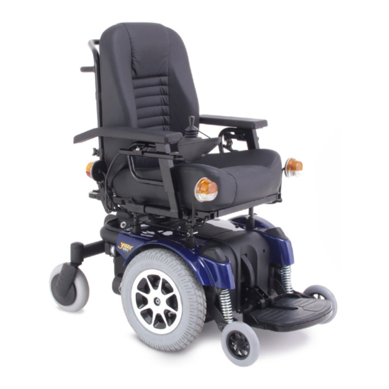
SEATBACK ARMRESTS JOYSTICK SEAT ASSEMBLY CONTROLLER (REMOTE PLUS SHOWN) SEAT BASE BODY SHROUD FOOTREST POWER BASE ASSEMBLY ANTI-TIP WHEELS CASTER WHEEL DRIVE WHEEL Figure 2. The Jazzy 1121 (Shown with optional lighting system.) WWW.PRIDEMOBILITY.COM JAZZY1121/REV C/SEPTEMBER 2002... - Page 13 70-amp Dynamic Europa Remote Controller 70-amp P & G VSI Controller Weight Capacity: 136 kg Component Weights: Base: 61.5 kg Batteries: 17 kg each Warranty: Lifetime limited warranty on frame Two-year warranty on electronics Eighteen-month warranty on drive motors JAZZY 1121/REV C/SEPTEMBER 2002 WWW.PRIDEMOBILITY.COM...
- Page 14 ELECTRONICS TRAY FREEWHEEL LEVER FRONT SEAT TOWERS (UNDERNEATH ELECTRONICS TRAY) ONBOARD BATTERY CHARGER (UNDERNEATH ELECTRONICS TRAY) MOTOR/BRAKE ASSEMBLY Figure 3. The Jazzy 1121 Power Base CONTROLLER CONNECTOR MAIN CIRCUIT BREAKER CHARGER FUSES (UNDER COVER) ONBOARD CHARGER AC POWER LEAD AMMETER Figure 4.
- Page 15 As your front anti-tip wheels come in contact with an obstacle, the front anti-tip wheel assembly is drawn upward. At the same time, your motors are forced downward. This allows the motors to push the Jazzy 1121 over an obstacle without the possibility of becoming “hung up.”...
- Page 16 I I I . T H E J A Z Z Y 1 1 2 1 Manual Brake Release Lever For your convenience, your Jazzy is equipped with a manual brake release lever. See figures 5 and 6. This lever allows you to disengage the drive motors and maneuver the chair manually.
-
Page 17: Assembly
6. Route the cable to ensure that the cable cannot be pinched in the seat hinge. 7. Secure the controller cable to the armrest receiver with one or more wire ties. Figure 7. Unversal Mounting System JAZZY 1121/REV C/SEPTEMBER 2002 WWW.PRIDEMOBILITY.COM... -
Page 18: Comfort Adjustments
C O M F O R T A D J U S T M E N T S COMFORT ADJUSTMENTS After becoming familiar with your power chair’s operation, you may find the need to make some adjustments to increase your comfort, such as seat height and angle, armrest angle, footrest height and angle, and the controller’s position. - Page 19 BALL DETENT PIN To adjust the footrest angle: 1. Turn the setscrew clockwise to raise the front of the footrest. Figure 10. Footrest (Shroud removed.) 2. Turn the setscrew anticlockwise to lower the front of the footrest. JAZZY 1121/REV C/SEPTEMBER 2002 WWW.PRIDEMOBILITY.COM...
- Page 20 C O M F O R T A D J U S T M E N T S Swing-away Footrests SETSCREW Swing-away Footrests (SFRs) enable you to rotate the leg rests to the side before you transfer on or off your power chair. To move the SFRs: 1.
- Page 21 ANTI-TIP WHEEL BRACKET ANTI-TIP WHEEL Figure 15. Anti-Tip Wheel Assembly JAZZY 1121/REV C/SEPTEMBER 2002 WWW.PRIDEMOBILITY.COM...
-
Page 22: Batteries And Charging
1. Position the rear of your power chair close to a standard wall outlet. 2. Be certain the controller power is turned off and the freewheel levers are in the engaged position. See III. “The Jazzy 1121.” 3. Plug the charger AC power lead into the receptacle on the power base, then into the wall outlet. The power chair incorporates an inhibit function that disables the power chair when the charger is plugged into a wall outlet. - Page 23 If you use your power chair infrequently (once a week or less), you should charge the batteries at least once per week for 12 to 14 hours. NOTE: Keep your batteries fully charged and avoid deeply discharging your batteries. Do not charge the batteries for more than 24 hours at a charging cycle. JAZZY 1121/REV C/SEPTEMBER 2002 WWW.PRIDEMOBILITY.COM...
- Page 24 V I . B A T T E R I E S A N D C H A R G I N G How can I get maximum range or distance per charge? Rarely do you have an ideal driving situation such as smooth, flat, hard terrain with no wind, hills, or curves. More often you are presented with hills, pavement cracks, uneven and loosely packed surfaces, curves, and wind.
- Page 25 What about shipping? If you wish to use a freight company to ship your power chair to your final destination, repack your power chair in the original shipping container and ship the batteries in separate boxes. JAZZY 1121/REV C/SEPTEMBER 2002 WWW.PRIDEMOBILITY.COM...
-
Page 26: Operation
V I I . O P E R A T I O N VSI CONTROLLER The electronic controller is what you use to operate your power chair. It takes the battery voltage and sends it to the appropriate system. The electronic controller enables you to move the power chair, as well as monitor battery charge, electronic controller functions, and the condition of your electrical system. - Page 27 16. If you use an off-board charger, the charger current should not exceed 12 amps. Contact your authorized Pride provider for more information. CAUTION! Only chargers with Neutrik NC3MX plugs should be connected to the off-board charger/ programming socket. See your authorized Pride provider for more information. JAZZY 1121/REV C/SEPTEMBER 2002 WWW.PRIDEMOBILITY.COM...
-
Page 28: Troubleshooting
V I I . O P E R A T I O N NOTE: The socket may also be used for reprogramming the VSI. Contact your authorized Pride provider for more information. Controller Connector This connects the VSI to the power chair’s batteries, motors, and motor brakes. See figure 16. 3-pin Charger Inhibit Connector This connects the VSI to the onboard battery charger. - Page 29 The keypad is located directly in front of the joystick. See figure 19. It contains keys that you will use to control your power chair. On/Off Key The on/off key toggles the system power on and off. WARNING! Unless faced with an emergency situation, do not use the on/off key to stop the chair. This will JAZZY 1121/REV C/SEPTEMBER 2002 WWW.PRIDEMOBILITY.COM...
- Page 30 V I I . O P E R A T I O N cause the power chair to stop abruptly. WARNING! Always turn the power off when you are stationary to prevent unexpected movement. Mode Key Press the key to change speed setting or to activate the power accessories. See “Speed Settings” or “Power Accessories.” Speed Setting Indicator Indicates the selected speed setting.
-
Page 31: Speed Settings
Typically, the power module is mounted to the power base. See figure 3. The power module provides a power interface for the joystick module. It routes the battery power to the motors and other powered accessories such as lights and power seats. JAZZY 1121/REV C/SEPTEMBER 2002 WWW.PRIDEMOBILITY.COM... -
Page 32: Sleep Mode
V I I . O P E R A T I O N Actuator Lighting Module (Not Shown) The actuator lighting module is also located on the power base. The actuator lighting module provides a control and power interface between the power module, the lights, and/or the power seat actuator. Sleep Mode Your Remote Plus controller has a sleep mode feature. -
Page 33: Care And Maintenance
Make sure the drive tyres are inflated to 30 – 35 psi. WARNING! Overinflating tyres can cause them to explode and can result in personal injury. WARNING! Do not use a high pressure hose to inflate your tyres. JAZZY 1121/REV C/SEPTEMBER 2002 WWW.PRIDEMOBILITY.COM... -
Page 34: Daily Checks
V I I I . C A R E A N D M A I N T E N A N C E n Use a rubber conditioner on the tyre sidewalls to help preserve them. Never use a rubber conditioner on the tread area of the tyres;... - Page 35 2. Set the power chair up on blocks. 3. If you are changing a pneumatic tyre, completely deflate it before removing the wheel. 4. Use a socket spanner to remove the drive wheel nut from the center hub of the wheel. JAZZY 1121/REV C/SEPTEMBER 2002 WWW.PRIDEMOBILITY.COM...
-
Page 36: Battery Replacement
To replace the batteries: 1. Turn the power off. 2. Make sure that the power chair is in drive mode. See III. “The Jazzy 1121.” 3. Remove the ball detent pin that secures the footrest to the frame. See figure 10. - Page 37 Disconnect both batteries before load testing and follow the directions that come with the load tester. If either one of the batteries fails the load test, replace both of them. If your power chair still does not power up, contact your authorised Pride provider. JAZZY 1121/REV C/SEPTEMBER 2002 WWW.PRIDEMOBILITY.COM...
-
Page 38: Optional Accessories
I X . O P T I O N A L A C C E S S O R I E S OPTIONAL ACCESSORIES The following accessories are available from your authorised Pride provider. Positioning Belt The positioning belt is designed to support your torso so that you do not slide down or forward in the seat. n The positioning belt is not designed for use as a restraining device. -
Page 39: Warranty
SERVICE CHECKS AND WARRANTY SERVICE Warranty service can be performed by your authorised Pride provider. Please contact your authorised Pride provider for advice on the current cost affecting the service visit. JAZZY 1121/REV C/SEPTEMBER 2002 WWW.PRIDEMOBILITY.COM... - Page 40 N O T E S WWW.PRIDEMOBILITY.COM JAZZY1121/REV C/SEPTEMBER 2002...