Advertisement
Quick Links
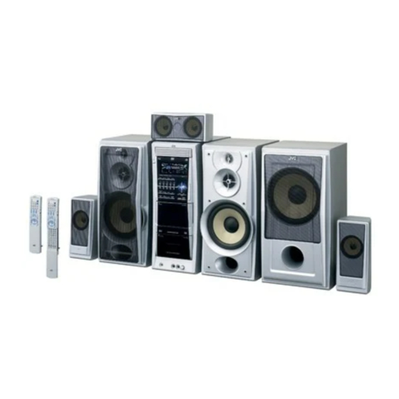
SERVICE MANUAL
COMPACT COMPONENT SYSTEM
5
2005
MB368
DX-T9,DX-T7,DX-T5
(CA-DXT7,CA-DXT9)
DX-T9
DX-T7
DX-T5
Lead free solder used in the board (material : Sn-Ag-Cu, melting point : 219 Centigrade)
1
PRECAUTION. . . . . . . . . . . . . . . . . . . . . . . . . . . . . . . . . . . . . . . . . . . . . . . . . . . . . . . . . . . . . . . . . . . . . . . . . 1-6
2
SPECIFIC SERVICE INSTRUCTIONS . . . . . . . . . . . . . . . . . . . . . . . . . . . . . . . . . . . . . . . . . . . . . . . . . . . . . . 1-9
3
DISASSEMBLY . . . . . . . . . . . . . . . . . . . . . . . . . . . . . . . . . . . . . . . . . . . . . . . . . . . . . . . . . . . . . . . . . . . . . . 1-10
4
ADJUSTMENT . . . . . . . . . . . . . . . . . . . . . . . . . . . . . . . . . . . . . . . . . . . . . . . . . . . . . . . . . . . . . . . . . . . . . . . 1-51
5
TROUBLESHOOTING . . . . . . . . . . . . . . . . . . . . . . . . . . . . . . . . . . . . . . . . . . . . . . . . . . . . . . . . . . . . . . . . . 1-61
(SP-XST5)
(SP-XT5)
(CA-DXT5)
Main body
Front speaker
Subwoofer
CA-DXT9
SP-XT9
SP-WT9
CA-DXT7
SP-XT7
SP-WT7
CA-DXT5
SP-XT5
TABLE OF CONTENTS
COPYRIGHT © 2005 Victor Company of Japan, Limited
(SP-XT5)
(SP-XST5)
Surround speaker
Center speaker
SP-XST9
SP-XCT9
SP-XST7
SP-XCT7
---
SP-XST5
SP-XCT5
DX-T9, DX-T7
Area suffix
A
------------------------
Australia
US ------------------------ Singapore
UW ----------- Brazil,Mexico,Peru
UX -------------------- Saudi Arabia
UG --- Turkey,South Africa,Egypt
UN ----------------------------- Asean
DX-T5
Area suffix
US ------------------------ Singapore
UW ----------- Brazil,Mexico,Peru
UX -------------------- Saudi Arabia
UY ------------------------ Argentina
UG --- Turkey,South Africa,Egypt
UN ----------------------------- Asean
No.MB368
2005/5
Advertisement

Related Manuals for JVC SP-XT9


Summary of Contents for JVC SP-XT9
- Page 1 (CA-DXT7,CA-DXT9) (SP-XST5) (SP-XT5) (CA-DXT5) (SP-XT5) (SP-XST5) UG --- Turkey,South Africa,Egypt UN ----------------------------- Asean Main body Front speaker Subwoofer Surround speaker Center speaker DX-T9 CA-DXT9 SP-XT9 SP-WT9 SP-XST9 SP-XCT9 DX-T7 CA-DXT7 SP-XT7 SP-WT7 SP-XST7 SP-XCT7 DX-T5 CA-DXT5 SP-XT5 SP-XST5 SP-XCT5 Lead free solder used in the board (material : Sn-Ag-Cu, melting point : 219 Centigrade) TABLE OF CONTENTS PRECAUTION.
- Page 2 DVD changer mechanism assembly section Remove the DVD changer mechanism assembly from the main body. (See "Removing the DVD changer mechanism assembly".) 3.2.1 Removing the tray assemblies (See Figs.1 to 5) (1) From the top side of the main body, remove the two screws Top cover A from the top cover and release the two joints a on the both sides of the DVD changer mechanism assembly.
- Page 3 Open det. lever Fig.3 Side(R) assembly Tray assemblies Fig.4 Tray assembly Fig.5 (No.MB368)1-25...
- Page 4 3.2.2 Removing the DVD servo board (See Figs.6 to 8) Caution: Solder the short land sections d on the DVD pickup before dis- connecting the card wire extending from the DVD pickup. If you do not follow this instruction, the DVD pickup may be dam- DVD pickup aged.
- Page 5 3.2.4 Removing the motor board (See Figs.9 and 10) (1) From the top side of the DVD changer mechanism assem- bly, remove the two belts from the motor pulleys. (See Fig.9.) Note: Take care not to attach grease on the belt. Belt Belt (2) Remove the two screws D attaching the motors to the load-...
- Page 6 3.2.6 Removing the DVD traverse mechanism assembly (See Fig.11) • Remove the tray assemblies and DVD servo board. DVD changer mechanism assembly (1) From the bottom side of the DVD changer mechanism as- sembly, remove the three screws F attaching the DVD traverse mechanism assembly.
- Page 7 3.2.7 Removing the DVD pickup (See Figs.12 to 14) • Remove the tray assemblies, DVD servo board and DVD DVD traverse mechanism assembly traverse mechanism assembly. Feed bracket (1) From the top side of the DVD traverse mechanism assem- Thrust spring bly, release the lock of the connector on the DVD pickup Connector and disconnect the card wire in the direction of the arrow.
- Page 8 DVD pickup Rack arm Guide shaft Rack arm spring Fig.14 Connector DVD pickup Screw shaft gear Fig.15 1-30 (No.MB368)
- Page 9 3.2.9 Removing the spindle motor board (See Figs.16 and 17) • Remove the tray assemblies, DVD servo board and DVD DVD traverse mechanism assembly traverse mechanism assembly. (1) From the top side of the DVD traverse mechanism assem- Spindle motor board bly, remove the wires from the soldered sections r on the spindle motor board.
- Page 10 3.2.10 Removing the feed motor (See Figs.18 and 19) • Remove the tray assemblies and DVD traverse mechanism Feed bracket assembly. (1) From the top side of the DVD traverse mechanism assem- Thrust spring bly, remove the screw K attaching the feed bracket and re- move the feed bracket from the sections t.
- Page 11 3.2.11 Removing the side (L) and tray switch board (See Figs.20 to 22) • Remove the tray assemblies. SIde(L) (1) From the topside of the DVD changer mechanism assem- bly, remove the two screws M attaching the side (L). (See Fig.20.) (2) From the left side of the DVD changer mechanism assem- bly, disconnect the connector...
- Page 12 3.2.12 Removing the side (R) assembly (See Fig.23 to 27) • Remove the tray assemblies and DVD servo board. Elevator spring (1) From the inside of the side (R) assembly, release the two tabs aa of the gear cover and remove the gear cover out- ward.
- Page 13 3.2.13 Removing the lifter assembly (See Figs.28 to 32) • Remove the tray assemblies, DVD servo board, side (L) and Hook side (R) assembly. (1) (1) From the top side of the DVD changer mechanism as- sembly, turn the gear 1 clockwise to move the lifter assem- bly upward.
- Page 14 3.2.14 Removing the sensor board and SV resistor (See Fig.33) • Remove the tray assemblies, side (L), side (R) assembly and Sensor board lifter assembly. (1) Remove the solders from the soldered sections aj on the sensor board and remove the wires. (2) Remove the two screws Q and take out the sensor board with the SV resistor.
- Page 15 3.2.15 Taking out the disc in the play mode (See Fig.34 to 37) Reference: Tray assembly Refer to "3.3.1 Removing the tray assemblies". (1) From the top side of the DVD changer mechanism assem- bly, remove the top cover. (2) Unlock the tray assemblies and draw out the tray assem- blies toward the front.
- Page 16 Tray stopper Main tray Sub tray Fig.36 Tray stopper Fig.37 1-38 (No.MB368)