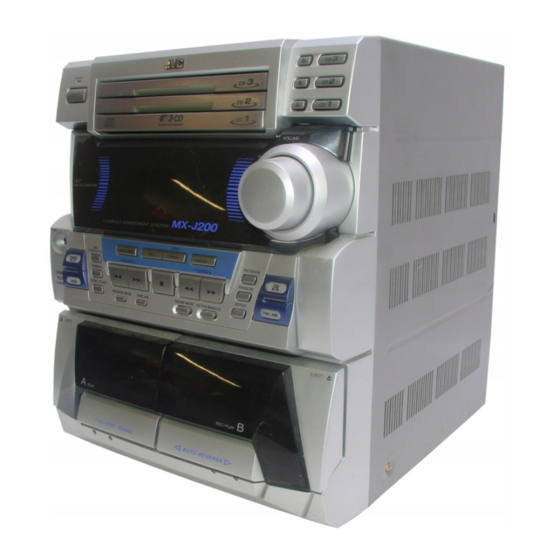
JVC MX-J200 Service Manual
Compact component system
Hide thumbs
Also See for MX-J200:
- Instructions manual (34 pages) ,
- Block diagram (34 pages) ,
- Instructions manual (32 pages)
Table of Contents
Advertisement
SERVICE MANUAL
COMPACT COMPONENT SYSTEM
RM-SMXJ300V REMOTE CONTROL
CLOCK
TIMER
1
2
3
–
SELECT
+
SLEEP
4
5
6
SET
AUX
7
8
9
FM MODE
FM/AM
10
+
10
CD1
CD2
CD3
PLAY MODE
C D
/CLEAR
TAPE
REC PAUSE
A – TAPE - B
SHIFT
SOUND
ACTIVE
VOLUME
MODE
BASS EX.
Contents
STANDBY
COMPACT
DIGITAL AUDIO
PLAY & EXCHANGE
1 BIT
DUAL D/A CONVERTER
PHONES
DEMO
REC
CLOCK/TIMER
SET
CANCEL
START/STOP
–
PRESET
TAPE
DUBBING
COMPU
CD REC START
AUX
PLAY
SOUND MODE
REVERSE MODE
TAPE A/B
CONTROL
EJECT
PLAY
AUTO REVERSE
FULL – LOGIC CONTROL
1-2
1-3
1-4
1-5
1-21
COPYRIGHT
2000 VICTOR COMPANY OF JAPAN, LTD.
CD
3
3
CD
2
CD
2
CD
1
CD
CD
1
VOLUME
+
–
DISPLAY
PROGRAM
+
TUNNER
C D
RANDOM
REPEAT
FM /AM
ACTIVE BASS EX
EJECT
REC/PLAY
Flow of functional operation
until TOC read
B
U.K.
E
Continental Europe
EN
Northern Europe
EE
Russia
EV
Eastern Europe
COMPACT
DIGITAL AUDIO
1-24
1-25
1-25
1-26
No.20860
Aug. 2000
Advertisement
Table of Contents

Related Manuals for JVC MX-J200


Summary of Contents for JVC MX-J200
- Page 1 MX-J200 SERVICE MANUAL COMPACT COMPONENT SYSTEM Area Suffix MX-J200 U.K. Continental Europe Northern Europe Russia Eastern Europe STANDBY COMPACT DIGITAL AUDIO PLAY & EXCHANGE VOLUME 1 BIT DUAL D/A CONVERTER RM-SMXJ300V REMOTE CONTROL CLOCK TIMER – MX-J200 – SELECT SLEEP...
-
Page 2: Safety Precautions
MX-J200 Safety Precautions 1. This design of this product contains special hardware and many circuits and components specially for safety purposes. For continued protection, no changes should be made to the original design unless authorized in writing by the manufacturer. - Page 3 MX-J200 Important for laser products 5.CAUTION : If safety switches malfunction, the laser is able 1.CLASS 1 LASER PRODUCT to function. 2.DANGER : Invisible laser radiation when open and inter 6.CAUTION : Use of controls, adjustments or performance of lock failed or defeated. Avoid direct exposure to beam.
- Page 4 MX-J200 Preventing static electricity 1. Grounding to prevent damage by static electricity Electrostatic discharge (ESD), which occurs when static electricity stored in the body, fabric, etc. is discharged, can destroy the laser diode in the traverse unit (optical pickup). Take care to prevent this when performing repairs.
- Page 5 MX-J200 Disassembly method <Main body> Metal cover Removing the metal cover (See Fig.1 to 3) Remove the six screws A attaching the metal cover on the back of the body. Remove the two screws B on both sides of the body.
- Page 6 MX-J200 CD changer mechanism assembly Removing the CD changer mechanism assembly (See Fig.4 to 7) Prior to performing the following procedures, remove the metal cover. Remove the two screws C attaching the CD changer Main board mechanism assembly on the top of the body.
- Page 7 MX-J200 Removing the front panel assembly Front panel assembly (See Fig.8 to 13) Main board Prior to performing the following procedures, remove the metal cover and the CD changer mechanism assembly. Disconnect the card wires from connector CN301, CN304, CN305 and the harness from CN302 on the inside of the main board.
- Page 8 MX-J200 Removing the heat sink cover and the Rear panel rear panel (See Fig.14 to 17) Prior to performing the following procedures, remove the metal cover and the CD changer mechanism assembly. It is not necessary to remove the front panel assembly.
- Page 9 MX-J200 Main board Removing the main board CN301 (See Fig.18 and 19) CN304 Prior to performing the following procedures, remove the metal cover, the CD changer mechanism assembly and the rear cover and the rear panel. CN305 It is not necessary to remove the front panel assembly.
- Page 10 MX-J200 Removing power transformer CN901A,CN901B assembly (See Fig.22 to 24) Prior to performing the following procedure, remove the metal cover and the CD changer mechanism assembly. Disconnect the harness from connector CN901A and CN901B on the inside of the main board.
- Page 11 MX-J200 <Front panel assembly> Removing cassette mechanism assembly (See Fig.25) Prior to performing the following procedure, remove the metal cover, the CD changer mechanism assembly and the front panel assembly. Disconnect the card wire from connector CN352 on the cassette amplifier board.
- Page 12 MX-J200 Removing the display board and the side Display board Bracket brackets (See Fig.28 and 29) Prior to performing the following procedure, remove the metal cover, CD changer mechanism assembly and the front panel assembly. CN708 Disconnect the card wires from connector CN701,...
- Page 13 MX-J200 Removing the CD Servo control board (See Fig.1) 1.Remove the metal cover. 2.Remove the CD changer mechanism assembly. 3.From bottom side the CD changer mechanism assembly, remove the two screws A retaining the CD servo control CN854 board. 4.Absorb the four soldered positions "a" of the right and left motors with a soldering absorber.
- Page 14 MX-J200 Stopper Check whether the lifter unit stopper has been caught into the hole at the section "e" of CD tray assembly as shown in Fig.5. Make sure that the driver unit elevator is positioned as shown in Fig.6 from to the second or fifth hole on the left side face of the CD changer mechanism assembly.
- Page 15 MX-J200 Cams R1, R2 assembly Removing the CD loading mechanism assembly(See Fig.10) While turning the cams R1 and R2 assembly in the arrow direction "h" ,align the shaft "i" of the CD loading mechanism assembly to the position shown in Fig.10.
- Page 16 MX-J200 Removing the cam unit (See Fig.14 ~17 ) Remove the CD loading mechanism assembly. While turning the cam gear "q", align the pawl "r" position of the drive unit to the notch position(Fig.15) on the cam gear "q". Pull out the drive unit and cylinder gear(See Fig.16).
- Page 17 MX-J200 Removing the actuator motor and belt Gear bracket (See Fig.18~21) Remove the two screws K retaining the gear bracket (See Fig.18). While pressing the pawl "t" fixing the gear bracket in the arrow direction, remove the gear bracket Pulley gear (See Fig.18).
- Page 18 MX-J200 Slit washer Removing the cams R1/R2 assembly and cam gear q(See Fig.22) Cam R2 Slit washer Remove the slit washer fixing the cams R1 and R2 assembly. Cam gear q By removing the two pawls "w" fixing the cam R1, separate R2 from R1.
- Page 19 MX-J200 < Cassette mechanism section > R/P head assembly Prior to performing the following procedures, remove the metal cover the CD changer mechanism assembly, the front panel assembly and cassette mechanism assembly. Removing the R/P head assembly (See Fig.1to2) Unsolder the head wire from the cassette mechanism board.
- Page 20 MX-J200 Removing the Capstan motor (See Fig.5to7) Remove the two screws D attaching the capstan motor. Unsolder the motor wire. Motor wire Marke red line Un solder Cassette mechanism assembly Fig.5 Capstan motor Fig.6 Removing the Capstan belt (See Fig.7)
- Page 21 MX-J200 Adjustment method Measurement instruments required for adjustment Radio input signal 1. Low frequency oscillator, AM modulation frequency : 400Hz This oscillator should have a capacity to output 0dB Modulation factor : 30% to 600ohm at an oscillation frequency of 50Hz-20kHz.
- Page 22 MX-J200 Arrangement of adjusting positions Cassette mechanism section (Mechanism A section) Cassette mechanism section (Back side) Head azimuth Head azimuth adjusting screw adjusting screw (Reverse side) (Forward side) Head azimuth Head azimuth Playback,recording and eraser adjusting screw adjusting screw Playback...
- Page 23 MX-J200 Reference values for confirmation items Adjusting Items Measurement Standard Measurement method positions conditions values Double tape Test tape After setting to the double speed motor, confirm 4,800+400/ Playback speed :VT712 (3kHz) that the frequency counter reading becomes -300Hz mechanism side...
- Page 24 MX-J200 Flow of functional operation until TOC read Check Point Slider turns REST Play Key Power ON Confirm that the voltage at the pin5 SW ON. of CN801 is "H"\"L"\"H". Automatic tuning of TE offset Check that the voltage at the...
- Page 25 MX-J200 Replacement of laser pickup Maintenance of laser pickup (1) Cleaning the pick up lens Before you replace the pick up, please try to Turn off the power switch and,disconnect the clean the lens with a alcohol soaked cotton power cord from the AC outlet.
- Page 26 MX-J200 Description of major ICs BA15218 (IC302,IC303) : OP AMP. OUT1 -IN1 OUT2 +IN1 -IN2 +IN2 BA3126N (IC401) : R/P Switch C O N T . TA8409S (IC851,IC852) : Motor driver 1.Pin layout 2.Pin function INPUT OUTPUT MODE OUT1 OUT2...
- Page 27 MX-J200 BA6897FP-W (IC801) : 4channel driver 1.Pin layout & Block diagram 13.3K 13.3K REGULATOR DRIVER MUTE T.S.D 13.3K 13.3K D . B U F T.S.D;Thermal shutdown 2.Pin function D.BUF:Drive buffer Symbol Function Symbol Function Driver CH1 - output Operation amplifier - input...
- Page 28 MX-J200 AN8806SB-W (IC601) : RF&SERVO AMP 1.Pin layout PD 1 36 PDAC LD 2 35 PDBD LDON 3 34 PDF 33 PDE LDP 4 32 PDER VCC 5 31 PDFR RF- 6 RF OUT 7 30 TBAL RF IN 8...
- Page 29 MX-J200 3. Pin function Pin No. symbol Function APC amp . Input terminal APC amp . Output terminal LD ON LD ON/OFF control terminal Connect to GND Power supply RF amp . Reversing input terminal RFamp . Output terminal RF OUT...
- Page 30 MX-J200 LC72136N (IC2) : PLL Frequency Synthesizer 1. Pin layout FM/AM LPFOUT LPFIN CLOCK FM/ST/VCO FMIN AM/FM AMIN IFCONT SDIN IFIN 2. Block diagram Phase Reference Detector Driver Charge Pump Swallow Counter Swallow Counter 1/16,1/17 4bit 1/16,1/17 4bit Unlock Detector...
- Page 31 MX-J200 TDA7442D (IC301) : Souse select PIN CONNECTION R_IN3 R_IN4 R_IN2 LOUT R_IN1 ROUT L_IN1 AGND L_IN2 L_IN3 CREF L_IN4 MUXOUTL IN(L) DIG-GND MUXOUT(R) TREBLE(R) IN(R) TREBLE(L) BIN(R) BOUT(R) BIN(L) BOUT(L) BLOCK DIAGRAM 5.6K 5.6nF 100nF 100nF 100nF 2.2 F...
- Page 32 MX-J200 MN35510 (IC651) : DIGITAL SERVO&DIGITAL SIGNAL PROCESSER 1. Terminal Layout 20 ~ 41 ~ 2.Block Diagram LRCKIN(MSEL) AVSS1 8TIMES BCLK(SSEL) AVDD1 DIGITAL OVER SAMPUNC SRDATAIN OUTR DEEMPHSIS DIGITAL FILTER 1BIT (PSEL) LOGIC IOSEL CLVS BLKCK OUTL CLDCK SBCK SUBC...
- Page 33 MX-J200 3. Description symbol I/O Description symbol I/O Description BCLK Not used Tracking error shunt signal output(H:shunt) LRCK Not used PLAY Not used SRDATA Not used WVEL Not used DVDD1 Power supply (Digital) RF signal input DVSS1 Connected to GND...
- Page 34 MX-J200 UPD78055GCA37 (IC251) : CD Changer control 1. Terminal Layout 20 ~ 41 ~ 2. Pin function symbol I/O Description Symbol Description DEMPH Deemphasis input LM DOWN L CAM down DEMPHO Deemphasis output RM UP R CAM up OS OFF...
- Page 35 MX-J200 VICTOR COMPANY OF JAPAN, LIMITED AUDIO & COMMUNICATION BUSINESS DIVISION PERSONAL & MOBILE NETWORK B.U. 10-1,1Chome,Ohwatari-machi,Maebashi-city,371-8543,Japan Printed in Japan No.20860 200008(V)
-
Page 36: Block Diagram
XM-200 Block diagram CN805 CN804 CN601 CN854 CN801 CN855 CN353 CN351 FFC-13P CN651 CN303 CN301 VCK VDATA CN304 CN305 CN704 CN702 CN701... - Page 37 XM-200 Standard schematic diagrams Power Transformer section E/EN/EE/EV/B Version 230V 50Hz T951 AC-PLUG F951 F952 T800mA T1.6A EI-66 Parts are safety assurance parts. When replacing those parts make sure to use the specified. SHEET 1/5...
- Page 38 XM-J200 Main section J301 R101 AUX-L R315 2.2K Q102 C102 50V1 2SC2785 R307 22K C301 1000P R102 6.8K SP-L + R116 R314 470K RY301 12V D303 1SS133 R202 6.8K SP-L - R112 6.8K C202 50V1 R201 R121 680 C315 50V1 R111 SP-R - C113...
- Page 39 XM-J200 Control section FL701 Q701 Q702 Q703 KTC3199 KTC3199 KTC3199 BASS R.D.S NEWS INFO S. MODE 1 CD MONO SLEEP W1005 PRGM RANDOM REPEAT DAILY -35V SW PWB (3) S1007 SW101 TUCE S1008 SW PWB (4) VDATA Q709 DTA114ES DTA114ES DTA114ES SFTY Q710...
- Page 40 XM-J200 Cassette amplifier section R352 REC-REV HEAD SW Q502 HALF-SW 2SD2144S HALF SW REC-FWD C504 0.018-M R502 6.8K C519 HEAD SW R501 100K C511 FFC-13P 25V10 R507 C9101 220P C503 TXL-P03H-A1 PB-HD WK354 CN354 R513 C515 25V4.7 CN353 C9102 FFC-13P PB-HD TXL-P03P-B1 IC402...
- Page 41 XM-J200 CD Servo & CD Mechanism control section CD CHANGER CONTROL RF & SERVO AMP. DIGITAL SERVO & DIGITAL SIGNAL PROCESSER CD signal SHEET 5/5...
- Page 42 XM-J200 Printed circuit boards Main board...
- Page 43 XM-J200 Control board...
- Page 44 XM-J200 Cassette amplifier board...
- Page 45 XM-J200 CD servo control board CD Tray section switch board Cam switch board 2-10...
- Page 46 XM-J200 PARTS LIST [ MX-J200 ] * All printed circuit boards and its assemblies are not available as service parts. Area suffix B ------------------------------- U.K. E ----------- Continental Europe EN ------------ Northern Europe EV -------------- Eastern Europe EE --------- Russian Federation...
- Page 47 XM-J200...
- Page 48 XM-J200 Exploded view of general assembly and parts list Block No. For spring protect...
- Page 49 GJ702244300812 SCREW TT3X8 BKT/CABINET GJ460170280101 HEAT SINK COVER --------------- MULTI-CONTROL BOARD GJ460450010101 CABINET FRONT GJ460450040101 KNOB MODE (TAPE/AUX) GJ460170330101 LOGO JVC GJ460450050101 KNOB MODE (CD/AM/FM) GJ460400080102 LENS DISPLAY GJ460450030101 KNOB CONTROL GJ702244300612 SCREW TT3X6 H.SINK/B./BOTTOM GJ460450060101 INDICATOR MODE (UPPER LEFT)
- Page 50 XM-J200 (Genral assembly) Parts list Block No. M1MM Item Parts number Parts name Q'ty Description Area GJ460400220101 DOOR CASS R GJ460400230101 LENS CASS R GJ460400240101 LENS CASS L GJ422253701 SPRING(LOCK)COMPRESSION GJ460400250101 HOLDER DOOR LOCKER GJ422250501 HOLDER LOCK GJ421038001 RIVET/SNAP GJ702244300612 SCREW TT3X6 FRONT C./BOTTOM GJ560170290101...
- Page 51 XM-J200 CD mechanism assembly and parts list Block No. Grease Point FG-87HS (Grease to apply have to be a little for the exchange.) FG-87HS FG-87HS FG-87HS EXL-M7TMB EXL-M7MB Parts list ( CD mechanism ) Block No. M2MM Parts number Parts name Q'ty Description Item...
- Page 52 XM-J200 CD changer mechanism assembly and parts list Block No. VC3-21M...
- Page 53 XM-J200 Parts list (CD changer mechanism) Block No. M3MM Item Parts number Parts name Q'ty Description Area VKS1144-003 CHASSIS VKS3698-003 TRAY GUIDE VKS5532-003 PULLEY GEAR VKB3000-164 BELT VKS5505-003 GEAR B VKS5506-002 GEAR C VKS5507-002 CROSS GEAR U VKS5508-002 CROSS GEAR L VKS5510-003 SELECT LEVER VKH5769-001...
- Page 54 XM-J200 (CD changer mechanism) Parts list Block No. M3MM Item Parts number Parts name Q'ty Description Area --------------- CD MECHA QGB2012J1-10 CONNECTOR VKW5187-001 VYSA1R2-033 SPACER FOR EWS176-008 LE30611-001A C.B HOLDER FOR CD CB QYSBSF3008Z SCREW FOR HOLDER QUQ610-1509AJ CARD WIRE TRAVERSE 15 EWS176-008 FLAT WIRE...
- Page 55 XM-J200 Cassette mechanism assembly and parts list Block No. Unit number : CMAT5Z214A Parts list ( Cassette mechanism ) Block No. M4MM Parts name Q'ty Item Parts number Area Description 03-1 F513-852 PLATE HD BLK F513-855 PLATE HD BLK 03-2 F525-336 MTR MAIN BLK F522-060...
-
Page 56: Electrical Parts List
XM-J200 Electrical parts list (Main board) Electrical parts list Block No. 01 Item Remarks Parts number Parts name Area Item Parts number Parts name Remarks Area GJ116415921 C.CAPACITOR 0.1MF F Z 50V C 111 GJ283118232432 CAPACITOR 100V K 0.082UF GJ116415921 C.CAPACITOR 0.1MF F Z 50V C 112... - Page 57 XM-J200 (Main board) Block No. 01 Electrical parts list Item Remarks Item Remarks Parts number Parts name Area Parts number Parts name Area C 321 GJ116230621 A.CAPACITOR 16V Y M 0.01UF D 11 1SS133T-77 DIODE GJ871999133 C 322 GJ270141060310 E.CAPACITOR 25V VX M 10UF D 12 1SS133T-77...
- Page 58 XM-J200 Block No. 01 Electrical parts list (Main board) Item Remarks Item Parts number Parts name Remarks Area Parts number Parts name Area DTA114YSTP TRANSISTOR GJ872990281 R 54 GJ250081822103 CARBON RESISTOR 1/6W J 1.8K DTC114YSTP TRANSISTOR GJ872990437 R 55 GJ250084722103 CARBON RESISTOR 1/6W J 4.7K Q 51...
- Page 59 XM-J200 Block No. 01 Electrical parts list (Main board) Item Remarks Item Remarks Parts number Parts name Area Parts number Parts name Area R 207 GJ250082732103 CARBON RESISTOR 1/6W J 27K R 330 GJ250082212103 CARBON RESISTOR 1/6W J 220 R 208 GJ250081042103 CARBON RESISTOR 1/6W J 100K...
- Page 60 XM-J200 Block No. 02 Electrical parts list (Display board) Item Remarks Item Remarks Parts number Parts name Area Parts number Parts name Area C 701 GJ116415921 C.CAPACITOR 0.1MF F Z 50V R 714 GJ250081022103 CARBON RESISTOR 1/6W J 1K C 702 GJ112689891 E.CAPACITOR 220MF 20% 10V...
- Page 61 XM-J200 Block No. 02 (Multi-control board) Block No. 03 Electrical parts list (Display board) Electrical parts list Item Remarks Item Parts number Parts name Remarks Area Parts number Parts name Area R 787 GJ250081032103 CARBON RESISTOR 1/6W J 10K CN101 GJ169537131 CONNECTOR 10PIN WHT...
- Page 62 XM-J200 Block No. 04 Electrical parts list (Power switch board) Item Remarks Parts number Parts name Area LED11 GJ374301012101 R1006 GJ250086812103 CARBON RESISTOR 1/6W J 680 S1001 GJ390110181120 TACT SWITCH POWER W1002 GJ353030140107 CABLE FLAT 3PINS (Eject switch board) Block No. 05 Electrical parts list Item Remarks...
- Page 63 XM-J200 Block No. 08 Electrical parts list (Cassette amplifier board) Item Remarks Item Remarks Parts number Parts name Area Parts number Parts name Area C 351 GJ270192250310 E.CAPACITOR 50V VX M 2.2UF C9001 GJ116229421 A.CAPACITOR 50V B K 1000PF C 352 GJ270121070310 E.CAPACITOR 16V VX M 100UF...
- Page 64 XM-J200 Block No. 08 Electrical parts list (Cassette amplifier board) Item Remarks Item Remarks Parts number Parts name Area Parts number Parts name Area R 364 GJ250081032103 CARBON RESISTOR 1/6W J 10K R 517 GJ250082232103 CARBON RESISTOR 1/6W J 22K R 365 GJ250081032103 CARBON RESISTOR...
- Page 65 XM-J200 Block No. 10 Electrical parts list (CD servo board) Item Remarks Item Remarks Parts number Parts name Area Parts number Parts name Area C 251 NCS21HJ-100X C CAPACITOR CN651 QGF1016F1-19 CONNECTOR MAIN C 252 NCS21HJ-100X C CAPACITOR CN652 QGF1016F1-05 CONNECTOR C 253 NCB21EK-104X...
- Page 66 XM-J200 Block No. 10 Electrical parts list (CD servo board) Item Remarks Item Remarks Parts number Parts name Area Parts number Parts name Area R 612 NRSA02J-125X MG RESISTOR R 863 NRSA02J-102X MG RESISTOR R 631 NRSA02J-2R2X MG RESISTOR R 864 NRSA02J-102X MG RESISTOR R 632...
- Page 67 XM-J200 Packing materials and accessories parts list Block No. Block No. 3-22...
- Page 68 XM-J200 (Packing B,E,EN,EV) Parts list Block No. M5MM Item Parts number Parts name Q'ty Description Area GJ560450110101 CARTON GJ560450120101 CARTON SPEAKER BOX GJ560400140101 POLYFOAM RIGHT GJ560400130101 POLYFOAM LEFT GJ560400160101 POLYFOAM BOTTOM GJ560400150101 POLYFOAM TOP GJ740082550400 POLYBAG REMOTE CONTROL GJ740666420300 POLYBAG GJ740362550000 POLYBAG INSTRUCTIONS...
- Page 69 XM-J200 Packing materials and accessories parts list Block No. Block No. 3-24...
- Page 70 XM-J200 Parts list (Packing EE) Block No. M7MM Item Parts number Parts name Q'ty Description Area GJ560450130201 CARTON GJ560400120101 POLYFOAM RIGHT GJ560400110101 POLYFOAM LEFT GJ560400160101 POLYFOAM BOTTOM GJ560400150101 POLYFOAM TOP GJ740082550400 POLYBAG REMOTE CONTROL GJ740666420300 POLYBAG GJ740362550000 POLYBAG INSTRUCTIONS GJ740486230300 POLYBAG SPEAKER BOX P 10...