Advertisement
Quick Links
INSTALLATION GUIDE
SCXI -1314 U
™
Introduction
™
™
National Instruments
, ni.com
trademarks or trade names of their respective companies.
322859A-01
NIVERSAL
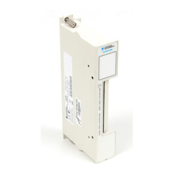
This guide describes how to install and use the SCXI-1314 terminal block
with your SCXI-1520 module.
The SCXI-1314 terminal block is used with the SCXI-1520 universal
strain/bridge module enabling you to conveniently connect strain gauges
through screw terminals. There are 88 screw terminals arranged in eight
groups of 11. Each group corresponds to one of the eight channels available
on the SCXI-1520. (Refer to Figure 2 for a diagram of terminal locations.)
The signal names of the terminals for each channel are listed in Table 1.
Signal Name
P+
P–
S+
S–
QTR
RS+
RS–
SCA
(2 terminals)
SCB
(2 terminals)
Each channel input contains screw terminals that connect to the inputs of
the SCXI-1520, two precision 100 kΩ shunt calibration resistors, and a
precision quarter-bridge completion resistor. The SCXI-1520 contains
™
, and SCXI
are trademarks of National Instruments Corporation. Product and company names mentioned herein are
© Copyright 2000 National Instruments Corp. All rights reserved.
S
T
TRAIN
ERMINAL
Table 1. Signal Names
Condition
Positive excitation signal
Negative excitation signal
Positive input signal
Negative input signal
Quarter-bridge completion resistor connection
Positive remote sense signal
Negative remote sense signal
Shunt calibration A signal
Shunt calibration B signal
B
LOCK
August 2000
Advertisement

Summary of Contents for National Instruments SCXI -1314
- Page 1 ™ National Instruments , ni.com , and SCXI are trademarks of National Instruments Corporation. Product and company names mentioned herein are trademarks or trade names of their respective companies. 322859A-01 © Copyright 2000 National Instruments Corp. All rights reserved. August 2000...
-
Page 2: What You Need To Get Started
relays that switch the resistors in and out of the input circuit to provide shunt calibration and quarter-bridge completion. The quarter-bridge completion resistor has a factory default value of 350 Ω for use with a 350 Ω strain gauge. These resistors are placed in sockets on the terminal block so you can easily replace them with resistors suitable to your specific strain gauge. -
Page 3: Connecting The Signals
Exposed wire increases the risk of a short circuit that can cause circuit failure. When connecting your signals to the SCXI-1314, follow the labeling on the SCXI-1314, as indicated in Figure 2. © National Instruments Corporation SCXI-1314 Universal Strain Terminal Block... - Page 4 P– P– P– P– P– P– P– P– P– P– S– S– S– S– S– S– S– S– S– S– RS– RS– RS– RS– RS– RS– RS– RS– RS– RS– SCXI-1314 UNIVERSAL STRAIN ASSY187212A-01 P– P– P– P– P– P– P–...
-
Page 5: Installing The Terminal Block
350 Ω completion resistor....±0.1% 100 kΩ shunt calibration resistor..±0.1% Temperature coefficient of resistors 120 Ω completion resistor....±10 ppm/°C 350 Ω completion resistor....±10 ppm/°C 100 kΩ shunt calibration resistor..±10 ppm/°C © National Instruments Corporation SCXI-1314 Universal Strain Terminal Block... - Page 6 Mechanical Resistor sockets Mating lead size.......0.023 to 0.026 in. Mating lead length......0.110 to 0.175 in. Lead spacing........0.500 in. Environment Operating temperature ......0 to 50 °C Storage temperature ........–20 to 70 °C Relative humidity ........10 to 90% Indoor use only SCXI-1314 Universal Strain Terminal Block ni.com...


