Table of Contents
Advertisement
Quick Links
SCXI -1321 O
™
S
-C
HUNT
ALIBRATION
T
B
ERMINAL
Conventions
»
bold
LabVIEW™, National Instruments™, NI™, ni.com™, NI-DAQ™, and SCXI™ are trademarks of National Instruments
Corporation. Product and company names mentioned herein are trademarks or trade names of their respective
companies. For patents covering National Instruments products, refer to the appropriate location: Help»Patents in your
software, the patents.txt file on your CD, or ni.com/patents.
ni.com
© 1998–2003 National Instruments Corp. All rights reserved.
-N
FFSET
H
IGH
I
LOCK
NSTALLATION
This guide describes how to install and use the SCXI-1321 offset-null
and shunt-calibration terminal block with the SCXI-1121 module. You can
only use the SCXI-1321 terminal block with SCXI-1121 revision C or later
modules. In addition to the 18 screw terminals, the SCXI-1321 has circuitry
for offset-null adjustment of Wheatstone bridges, and a socketed shunt
resistor for strain-gauge shunt calibration. This terminal block was
primarily designed for Wheatstone bridge transducers such as strain
gauges, although it can easily accommodate thermocouples, RTDs,
thermistors, millivolt sources, volt sources, and current-loop receivers.
Thermocouples have cold-junction compensation (CJC) support.
The following conventions are used in this guide:
The » symbol leads you through nested menu items and dialog box options
to a final action. The sequence File»Page Setup»Options directs you to
pull down the File menu, select the Page Setup item, and select Options
from the last dialog box.
This icon denotes a note, which alerts you to important information.
This icon denotes a caution, which advises you of precautions to take to
avoid injury, data loss, or a system crash. When this symbol is marked on
the product, refer to the Read Me First: Safety and Radio-Frequency
Interference document, shipped with the product, for precautions to take.
Bold text denotes items that you must select or click in the software, such
as menu items and dialog box options. Bold text also denotes parameter
names.
ULL AND
-V
OLTAGE
G
UIDE
January 2003
321924C-01
Advertisement
Table of Contents

Related Manuals for National Instruments SCXI-1321


Summary of Contents for National Instruments SCXI-1321
- Page 1 LabVIEW™, National Instruments™, NI™, ni.com™, NI-DAQ™, and SCXI™ are trademarks of National Instruments Corporation. Product and company names mentioned herein are trademarks or trade names of their respective companies. For patents covering National Instruments products, refer to the appropriate location: Help»Patents in your software, the patents.txt file on your CD, or ni.com/patents.
-
Page 2: What You Need To Get Started
Italic text in this font denotes text that is a placeholder for a word or value monospace italic that you must supply. What You Need to Get Started To set up and use the SCXI-1321, you need the following items: ❑ ❑ ❑... -
Page 3: Connecting The Signals
Connect safety earth ground to the safety-ground lug. Refer to the Read Me First: Safety and Radio-Frequency Interference document for connection information. Reinstall the strain-relief bar, and tighten the strain-relief screws. in the Installing the Terminal Block section. SCXI-1321 Terminal Block Installation Guide... - Page 4 Back View 1 Strain-Relief Bar 3 Safety-Ground Lug 2 Strain-Relief Screws 4 Mating Connector SCXI-1321 Terminal Block Installation Guide 5 Thumbscrew 6 Top-Cover Screws Figure 1. SCXI-1321 Parts Locator Diagram Front View 7 Top Cover ni.com...
-
Page 5: Installing The Terminal Block
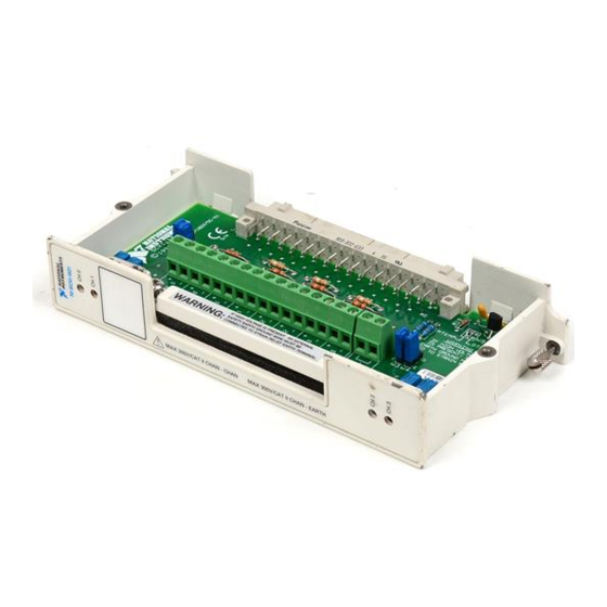
12 R10 (CH3 Shunt Resistor) 13 W5 (CJC Mode) 14 Warning Label Figure 2. SCXI-1321 Circuit Parts Locator Diagram Connect the module front connector to its connector on the terminal block. Make sure that the module top and bottom thumbscrews do not obstruct the rear panel of the terminal block. -
Page 6: Specifications
Channel-to-earth ...300 V, Installation Category II Channel-to-channel...300 V, Installation Category II The temperature sensor accuracy includes tolerances in all component values caused by temperature and loading, and self-heating. SCXI-1321 Terminal Block Installation Guide Accuracy ...0.9 °C Output ...10 mV/°C from 0 to 55 °C ...301 kΩ... -
Page 7: Electromagnetic Compatibility
Humidity ... 10 to 90% RH, noncondensing Maximum altitude ... 2,000 meters Pollution Degree (indoor use only) ... 2 Safety The SCXI-1321 is designed to meet the requirements of the following standards of safety for electrical equipment for measurement, control and laboratory use: •... - Page 8 Conformity Information at Performed or Supported Signal Conditioning This section provides information on types of signal conditioning performed by the SCXI-1321 or is supported by it. Offset Nulling Offset nulling is a hardware nulling procedure used with Wheatstone-bridge transducers that have an initial offset error. Correcting this error improves measurement accuracy.
- Page 9 (range of trim potentiometer + nulling resistor) is the nominal strain-gauge resistance value = ±2.56 mV nulling range = 3.3 V = 120 Ω = 39 kΩ null = 120 Ω Nulling Resistor null – ---------------------------------------------------------- - null null SCXI-1321 Terminal Block Installation Guide...
- Page 10 SCXI-1121 – CH– 4.5 kΩ – 4.5 kΩ EX– Note: R and R are completion resistors. SCXI-1321 Terminal Block Installation Guide ε ------------------------------- GF 1 strained voltage static unstrained voltage ------------------------------------------------------------------------------------------------------- - SCXI-1321 SCAL 301 kΩ CH– Null Trim 10 kΩ...
- Page 11 Note: R and R are completion resistors. © National Instruments Corporation SCXI-1321 SCAL 301 kΩ CH– Null Trim 10 kΩ 39.1 kΩ EX– Trim Figure 4. Half-Bridge Nulling Circuit Transducer (gauge) (gauge) EX– (Screw Adjusts Potentiometer) SCXI-1321 Terminal Block Installation Guide...
-
Page 12: Shunt Calibration
You can use LabVIEW to take measurements from channels with the shunt resistors connected by using the SCXI channel string ob x ! sc y ! md z ! shunt w where SCXI-1321 Terminal Block Installation Guide SCXI-1321 SCAL 301 kΩ... - Page 13 Table 3. Socket to Channel Relationship Channel ---------------------------------------------------------------- - change SCAL = 301 kΩ and a quarter-bridge 120 Ω strain SCAL , for example. Refer to the LabVIEW Shunt Resistor Socket shunting SCAL SCAL – ------- SCAL SCAL SCXI-1321 Terminal Block Installation Guide should...
-
Page 14: Cold-Junction Compensation
CJC is used only with thermocouples and provides improved accuracy of temperature measurements. The CJC temperature sensor, mounted in the SCXI-1321, outputs 10 mV/°C and has an accuracy of ±0.9 °C over the 0 to 55 °C temperature range. To determine the temperature, use the... - Page 15 DTEMP uses CH4 analog input, therefore CH3 is not available. RTD and Thermistor Excitation By properly setting the excitation, you can configure the SCXI-1321 on a per channel basis for RTD and thermistor measurements. With the SCXI-1121 excitation set in the current mode, you must disable the nulling circuit of the channel of interest.
- Page 16 Table 4. Jumper Settings of the Nulling Circuits (Continued) Jumper Position Description Nulling circuit of Channel 2 is enabled (factory default setting) Nulling circuit of Channel 2 is disabled Nulling circuit of Channel 3 is enabled (factory default setting) Nulling circuit of Channel 3 is disabled *321924C-01* 321924C-01...