Table of Contents
Advertisement
SERVICE
AIR CONDITIONER
ROOM AIR CONDITIONER
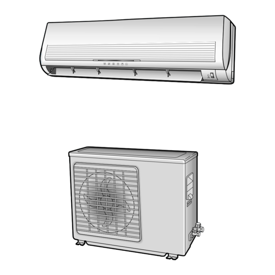
INDOOR UNIT
SH12VCD
SH09VCD
Manual
1. Precautions
2. Product Specifications
3. Operating Instructions and
Installation
4. Disassembly and Reassembly
5. Troubleshooting
6. Exploded Views and Parts List
7. PCB Diagrams
8. Wiring Diagrams
OUTDOOR UNIT
SH12VCDX
SH09VCDX
CONTENTS
Advertisement
Table of Contents

Related Manuals for Samsung SH12VCD


Summary of Contents for Samsung SH12VCD
-
Page 1: Room Air Conditioner
ROOM AIR CONDITIONER INDOOR UNIT OUTDOOR UNIT SH12VCD SH12VCDX SH09VCD SH09VCDX Manual SERVICE AIR CONDITIONER CONTENTS 1. Precautions 2. Product Specifications 3. Operating Instructions and Installation 4. Disassembly and Reassembly 5. Troubleshooting 6. Exploded Views and Parts List 7. PCB Diagrams... -
Page 2: Precautions
Relocate the unit if necessary. 9. Keep children away from the unit while it is being repaired. 10. Be sure to clean the unit and its surrounding area. Fig. 1-3 No Kids Nearby! Fig. 1-4 Clean the Unit Samsung Electronics... - Page 3 MEMO Samsung Electronics...
-
Page 4: Product Specifications
2. Product Specifications 2-1 Table Model(Indoor/Outdoor) SH09VCD/SH09VCDX Remark SH12VCD/SH12VCDX Item 1-220 / 240-50 Power Source ø-V-Hz 1-220 / 240-50 3510(2340~4100) 2630(1640~3010) Capacity 12000(8000~14000) 9000(5600~10300) Btu/h 9.0(11~7.7) Energy efficiency ratio Btu/wh 8.6(10.8~7.8) Cooling Air Flow /min Moisture removal 39 / 37 / 35... - Page 5 2-2 Dimensions 2-2-1 Indoor Unit (Front view) Air out (Remote control) Installation plate Samsung Electronics...
- Page 6 P roduct Specifications 2-2-2 Outdoor Unit (Front view) (Rear view) 145 55 Samsung Electronics...
-
Page 7: Refrigerating Cycle Block Diagram
2-3 Refrigerating Cycle Block Diagram INDOOR UNIT OUTDOOR UNIT Capillary tube 2-way valve Liquid side Heat Heat exchanger exchanger (Evaporator) (Condenser) Gas side 3-way valve 4-way valve Cooling Heating Compressor Gas leak check point Samsung Electronics... -
Page 8: Operating Instructions And
To select the 5 way function with the remote control, press the (5 way) button one or more times until the desired mode is selected. Each time you press the (5 way) button, each 5 way indicator on the indoor unit lights up in order. Samsung Electronics... - Page 9 18˚C less 27˚C less Heating ture at the opera- then switch to the selected fan speed. This tion start. period is to allow the indoor unit's heat- 23˚C exchanger to prewarm until emitting 21˚C warm air. Samsung Electronics...
-
Page 10: Dry Mode
*Memory louver : When ON/OFF button When the temperature has been raised by is pressed at stop state, the BLADE-H total of 2°C, that temperature is main- returns to its original location which is tained. operating state before stop. Samsung Electronics... -
Page 11: Self Diagnosis
Trouble of the PTC circuit of the ON/OFF button is pressed or whenever outdoor change occurs to the condition which is set Trouble of AC current sensor(open/short) and Leakage up or select, the compulsory operation of refrigerant (R-22) mode, buzzer is sounded "beep". Samsung Electronics... -
Page 12: Selecting Area For Installation
It is harmful to the air conditioner if it is used in the following environments: greasy areas (including areas near machines), salty areas such as coast areas, areas where sulfuric gas is present such as hot spring areas. Contact your dealer for advice. Samsung Electronics... -
Page 13: Refrigerant Refill
Charging line 7. Stop operation of the air conditioner. 8. Close the 3-way valve, disconnect the pressure gauge, and open the 3-way valve again. 9. Close the cap of each valve. Samsung Electronics... -
Page 14: Refrigerant Adjustment
Operating Instructions and Installation • MODEL NAME : SH12VCD(SH12VCDX) • MODEL NAME : SH09VCD(SH09VCDX) 32.4 32.4 30.6 30.6 28.8 28.8 27.0 27.0 24.0 24.0 21.5 21.5 Outdoor inlet air DB temp.(˚C) Outdoor inlet air DB temp.(˚C) 3-2-2(b) Refrigerant Adjustment Class... -
Page 15: Disassembly And Reassembly
7) Pull the upper left and right of discharge softly for the outside cover to be pulled out. 8) Pull softly the lower part of discharge and push it up. Caution; Assemble the front panel and fix the hooks of left and right. Samsung Electronics... - Page 16 2) Loosen the fixing two screws and separate the motor holder. 3) Loosen the fixing screw of fan motor. (By use of M3 wrench) 4) Separate the fan motor from the fan. 5) Separate the fan from the left holder bear- ing. Samsung Electronics...
- Page 17 3) Loosen five fixing screws and separate the Cabi-Upper. 4) Loosen five fixing screws from the Ass’y-Control Out. 5) Separate the Terminal-Housing from the Ass’y-Control Out. 6) Separate the Ass’y-Control Out from the outdoor unit. 7) Loosen seven fixing screws and separate the Cabi-Side. Samsung Electronics...
- Page 18 4) Loosen four fixing screws to separate the motor. Heat Exchanger 1) Do “1” above. 2) Loosen three fixing screws of Ass’y-Frame and Partition. 3) Disassemble the inlet and outlet pipe by welding. 4) Separate the heat exchanger. Samsung Electronics...
- Page 19 3) Disassemble the inlet and outlet pipe of compressor by welding. 4) Disassemble the inlet and outlet pipe of condenser by welding. 5) Loosen the three bolts of the lower part. 6) Separate the compressor. Samsung Electronics...
-
Page 20: Troubleshooting
# Auto restart function is the convenient function where the operation state is memorized remote controller when in the Memory IC during the blackout and the operation restarts when the power comes plugged back. Samsung Electronics... - Page 21 Abnormal communication (Indoor - Outdoor unit) \Abnormal increase of operation current Abnormal increase of discharge and OLP temperature Over current of IPM circuit Trouble of the PTC circuit of the outdoor Trouble of AC current sensor (open/short) and Leakage of refrigerant(R-22) Samsung Electronics...
- Page 22 Over voltage and current of PFC circuit Trouble of DC link voltage circuit Trouble of discharge temp-sensor(open/short) Trouble of outdoor temp-sensor(open/short) Trouble of deice temp-sensor(open/short) Trouble of OLP temp-sensor(open/short) Trouble of AC current sensor(open/short) and Leakage of refrigerant(R-22) Samsung Electronics...
- Page 23 → Check of the instantaneous over-current protection Timer( ), POWER( ) lamp flickering mode of IPM circuit (5-3-9) → Check the abnormal increase of the comp Nature( ), POWER lamp( flickering discharge gas temperature and OLP protection mode.(5-3-10) Samsung Electronics...
- Page 24 Ambient temperature 20°C 25°C 30°C 35°C 40°C 15°C (°C) Resistance of 6.94 5.83 14.68 12.09 8.31 thermistor [KΩ] Samsung Electronics...
- Page 25 → If the red lamp (LED 3) is not on, check the power part of control board of outdoor unit. ♦Check the connection of reactor. → If the red lamp (LED3) is on and green lamp is flickering, it is normal. Samsung Electronics...
- Page 26 ♦If two outdoor units are operating face to face. (the bad ventilation is made) → Reinstall the outdoor unit for the good ventilation. ♦The air circulation is bad due to the attachment of falling leaves → Take away the leaves for the good ventilation. Samsung Electronics...
- Page 27 (Unit defect) ♦If the comp is locked. → Replace the comp. ♦If the comp is operating without the revolution of fan motor → Take out the protection cover. → Check the fan motor connector and replace the fan motor. Samsung Electronics...
-
Page 28: Fault Diagnosis Of Major Parts
Black, White 350±10% ∞, OΩ … open or short Abnormal Stepping Motor Measure resistance between red wire and each terminal. (UP/DOWN swing motor) Normal Approx. 380Ω at ambient temperature (20°C ~30°C) ∞, OΩ … open or short Abnormal Samsung Electronics... -
Page 29: Set Up The Model Option
Press the marked key to input the option number. example) 021E31 Result) Go to 4th step if it displays as shown in the right (The number increases from 1~9, and A, b, C, d, E, F whenever pressing the key.) 5-10 Samsung Electronics... - Page 30 ; since it Refer to the right side if is the case that the option number is out of the error appears. the input range, check the option number again and do again the steps from 1 - 6steps Samsung Electronics 5-11...
-
Page 31: Option Code
Troubleshooting <Table of the option code> MODEL OPTION CODE SH12VCD 007315-10123F SH09VCD 007d08-1010Fb 5-12 Samsung Electronics... - Page 32 MEMO Samsung Electronics 5-13...
-
Page 33: Exploded Views And Parts List
6. Exploded Views and Parts List 6-1 Indoor Unit 20-6 20-6-1 20-1 20-4 20-5 20-3 20-2 13-2 13-3 13-4 13-1 You can search for the updated part code number through the ITSELF. URL : http://itself.sec.samsung.co.kr Samsung Electronics... - Page 34 Exploded Views and Parts List Parts List Q’TY CODE NO Description SH12VCD SH09VCD DB64-00354A GRILLE-AIR INLET DB63-00064A GUARD-AIR FILTER DB95-00287G ASS´Y-CLEANER FILTER DB63-00067A COVERTER-TERMINAL DB92-00248G ASSY PANEL-FRONT DB67-00051A SPACER-EVAP LOW DB67-00032A SPACER-EVAP UP DB63-00083A COVER U-BEND DB94-00040F ASSY-CROSS FAN DB60-20011A...
-
Page 35: Outdoor Unit
6-2 Outdoor Unit Samsung Electronics... - Page 36 DB32-10043F THERMISTOR-OLP 204CT/103AT DB60-30018A NUT-FLANGE M5,SM20C DB99-00187A ASSY-4WAY VALVE ASS’Y DB99-00168A ASSY-4WAY VALVE ASS’Y DB99-00186A ASS’Y-CAPI TUBE ASS’Y DB99-00169A ASS’Y-CAPI TUBE ASS’Y DB96-01588A ASS’Y-CONDENSER ASS’Y DB96-10502A ASS’Y-CONDENSER ASS’Y 21-1 DB32-10040D THERMISTOR-OUT ASS’Y DB64-00433A CABI-SIDE SECC-P DB64-00400A HANDLE-CABI RH Samsung Electronics...
- Page 37 6-3 Remote Control & PCB Box 6-3-1 ASS'Y Remote Control : (DB93-00251L) Parts List Remark Description Q’TY INLAY LCD CASE TOP KEY RUBBER ASS’Y PCB REMOCON CASE LOW BATTERY COVER Samsung Electronics...
- Page 38 1200nF, 450V, 39.6 x 16 x 27 CONNECTOR WIRE MF CAPACITOR ST730619 UL1015 AW#22, WHT CONNECTOR WIRE EARTH UL1015 AWG#20, GRN+YEL LEAD WIRE(N) UL1015 ASG#16, ORG LEAD WIRE(L) UL1015 AWG#16, SKY=BLUE LEAD WIRE(C) UL1015 AWG#16, BLK ASSY DISPLAY PC Samsung Electronics...
-
Page 39: Isometric View
Exploded Views and Parts List 6-3-3 ASS’Y-Control-Out(Outdoor unit) - 9K : DB93-00962A / 12K : DB93-00962B APPLY SILICONE SEALANT ASSY TERMINAL BLOCK DIAGRAM CONNECT THIS TO LOWER PART OF TERMINAL BLOCK ISOMETRIC VIEW Samsung Electronics... - Page 40 UL1015 AWG#16/SKY BLUE CONNECTOR WIRE POWER LSA13024/ENAMAL 18T CONNECTOR WIRE RUN CAP. UL1015 AWG#16/BLU UL1015 AWG#16/GRN, YEL CONNECTOR WIRE AC TR-22-1-13/2T FOAMLEX 165 x 30 x T2 MICA 18.4 x 23.3 (Hole : ø3.6) RUN CAPACITOR 1.7uF/ 400V Samsung Electronics...
-
Page 41: Pcb Diagrams
7. PCB Diagrams 7-1 ASS’Y PCB IN : DB93-00951A BOTTOM Samsung Electronics... -
Page 42: Fuse Holder
YW396-05AV,WHT CN42 CONNECTOR-HEADER SMW250-03,BLU CN41 CONNECTOR-HEADER SMW200-04,WHT CN91 CONNECTOR-HEADER SMW200-12,WHT CN61 CONNECTOR-HEADER SMW200-05,WHT ST11 TRANS SWITCHING DC12V DSA1 POSISTOR DSA-332M,2pF,MAX,100MOHM PC01 PHOTO-COUPLER TLP181GB PC31,32 PHOTO-COUPLER TLP181 PC02 PHOTO-COUPLER TLP620GR BZ61 BUZZER CBE2220BA FT72 FILTER LS403110 RY71 RELAY-POWER UKH-12S Samsung Electronics... - Page 43 7-2 ASS’Y PCB Control-Out : DB93-00953A Samsung Electronics...
- Page 44 PCB Diagrams BOTTOM Samsung Electronics...
- Page 45 65TL 250V,20A FUSE CLIP FUSE-CLIP FC61B H/S(PFC) HEAT SINK 27X17.5X40 IC51 IC-MASK S3C9434XZ0-SKB4 IC83 IC-LOGIC 74HCT00D,SOP-14 IC41 IC-LOGIC LM324D IC81 IC-LOGIC ULN2003ADR MICOM IC-MICOM TMP88PH47F(MASK),QFP IC15,IC21,IC31,IC32,IC54 IC-PHOTO-COUPLER TLP181(GRH-TLP),SOP,TP IC11 IC-PWM CONTROLLER TOP222P IC16 IC-REG KA78L05AZTA(0.1A Positive Vol Reg) Samsung Electronics...
- Page 46 AXIAL,MOR 2TSJ 100Kohm ,5%,2W,AA,TP R201 R-METAL OXIDE(S) AXIAL,MOR 2TSJ 47Kohm,,5%,2W,AA,TP) R301 R-METAL OXIDE(S) AXIAL,MOR 2TSJ 5.6Kohm,5%,2W,AA,TP) R104 R-METAL OXIDE(S) MOR 3TSJ 47Kohm,5%,3W,AA,TP) SURGE-ABSORBER AXIAL,300V,DSS-301 SURGE-ABSORBER AXIAL,500V,DSA-501 PT01 THERMISTER-PTC J512Q24E270M265 PT02 TRANS-PULSE PT_20A , 1.4mH VA02,VA05,VA06,VA07 VARISTER 470V,0.6W,50A,14MM,INR14D471K VA01,VA04 VARISTER 470V,0.6W,50A,14MM,INR20D471K Samsung Electronics...
- Page 47 Q’TY PCB-DISPLAY FR-1, T1.6 MODULE REMOCON KSM-713TH5 TACT SWITCH KPT-1105A C-CERAMIC CA 0A 50V 102K C-CERAMIC CA 0A 50V 104Z DIODE SWITCHING 1N4148 R-CARBON 470 1/2W 5% CONNECTOR WAFER SMAW200-05(WHT) C/W DIS & MODULE UL1007 AWG/26/11 HOLDER-LED HIPS Samsung Electronics...
-
Page 48: Wiring Diagrams
8. Wiring Diagrams 8-1 Indoor Unit Samsung Electronics... - Page 49 8-2 Outdoor Unit CODE NO. : DB98-03527A Samsung Electronics...
-
Page 50: Error Mode
Trouble of DC link voltage circuit Tourble fo discharge temp-sensor(open/short) Trouble of outdoor temp-sensor(open/short) Trouble of deice temp-sensor(Open/short) Trouble of OLP temp-sensor(open/short) Trouble of AC current sensor(open/short) and Leakage of refrigerant (R-22) : LAMP ON : LAMP FLICKERING : LAMP OFF Samsung Electronics... - Page 51 MEMO Samsung Electronics...
- Page 52 MEMO Samsung Electronics...
- Page 53 MEMO Samsung Electronics...
- Page 54 Itself Solution Integrated technology supporting electronic library http://itself.sec.samsung.co.kr Copyright © 2002 By Samsung Electronics Co., Ltd. All rights reserved. This manual may not, in whole or in part, be copied, photocopied, reproduced, translated, or converted to any electronic or machine readable from without prior written permission of Samsung Electronics Co., Ltd.
- Page 55 ELECTRONICS © Samsung Electronics Co., Ltd. Dec. 2002. Printed in Korea. Code No. DB98-08728A(1)