AudioCodes Mediant 800 MSBR Hardware Installation Manual
Multi-service business router
Hide thumbs
Also See for Mediant 800 MSBR:
- User manual (1002 pages) ,
- Hardware installation manual (72 pages) ,
- Configuration manual (74 pages)

Related Manuals for AudioCodes Mediant 800 MSBR


Summary of Contents for AudioCodes Mediant 800 MSBR
- Page 1 Mediant™ 800 MSBR Multi-Service Business Router SIP Protocol Hardware Installation Manual Version 6.6 February 2013 Document #: LTRT-10208...
-
Page 3: Table Of Contents
Hardware Installation Manual Contents Table of Contents Introduction ......................9 Unpacking the Device ..................11 Physical Description ..................13 Physical Dimensions ....................13 Front Panel Description ..................13 3.2.1 Ports and Buttons....................13 3.2.2 LEDs ........................15 3.2.2.1 LAN Interface LED ................... 15 3.2.2.2 Power-over-Ethernet LAN LED ............... - Page 4 Mediant 800 MSBR Maintenance – Replacing the Power Fuse ............. 45 A Notice for Installing CentOS Version 4.7 on OSN Server ......47 Hardware Installation Manual Document #: LTRT-10208...
- Page 5 Hardware Installation Manual Contents List of Figures Figure 3-1: Front Panel .......................... 13 Figure 3-2: Rear Panel .......................... 19 Figure 4-1: Wi-Fi Antenna ........................21 Figure 4-2: Attaching Antennas on Rear Panel ..................21 Figure 5-1: Location for Applying Rubber Foot ..................23 Figure 5-2: Mounting Bracket (Right) .....................
- Page 6 Mediant 800 MSBR List of Tables Table 3-1: Physical Dimensions ......................13 Table 3-2: Front Panel Description ......................14 Table 3-3: LAN LED Description ......................15 Table 3-4: PoE LAN LED Description ....................15 Table 3-5: Wi-Fi LED Description ......................16 Table 3-6: WAN LED Description ......................
-
Page 7: Weee Eu Directive
This document is subject to change without notice. Date Published: February-17-2013 Trademarks AudioCodes, AC, AudioCoded, Ardito, CTI2, CTI², CTI Squared, HD VoIP, HD VoIP Sounds Better, InTouch, IPmedia, Mediant, MediaPack, NetCoder, Netrake, Nuera, Open Solutions Network, OSN, Stretto, TrunkPack, VMAS, VoicePacketizer, VoIPerfect, VoIPerfectHD, What’s Inside Matters, Your Gateway To VoIP and 3GX are trademarks or... -
Page 8: Related Documentation
Disconnect the device from the mains and Telephone Network Voltage (TNV) before servicing. Documentation Feedback AudioCodes continually strives to produce high quality documentation. If you have any comments (suggestions or errors) regarding this document, please fill out the Documentation Feedback form on our Web site at http://www.audiocodes.com/downloads. -
Page 9: Introduction
Hardware Installation Manual 1. Introduction Introduction This document provides a hardware description of the Mediant 800 MSBR (hereafter referred to as device) and step-by-step procedures for cabling the device. The device provides the following optional, customer-ordered interfaces: Optional telephony interfaces: ... - Page 10 Mediant 800 MSBR Reader's Notes Hardware Installation Manual Document #: LTRT-10208...
-
Page 11: Unpacking The Device
One FXS Lifeline cable adapter (only for models with FXS interfaces) • Three Wi-Fi antennas (depending on Mediant 800 MSBR ordered model) • One AC power cable Check, retain and process any documents. If there are any damaged or missing items, notify your AudioCodes sales representative. Version 6.6 February 2013... - Page 12 Mediant 800 MSBR Reader's Notes Hardware Installation Manual Document #: LTRT-10208...
-
Page 13: Physical Description
Hardware Installation Manual 3. Physical Description Physical Description This section provides a physical description of the device. Physical Dimensions The device's physical dimensions and weight are listed in the table below: Table 3-1: Physical Dimensions Physical Specification Value Dimensions (H x W x D) 32 x 34.5 cm (12.6 x 13.6 inches) x 1U Weight 2.5 kg (5.5 lb) -
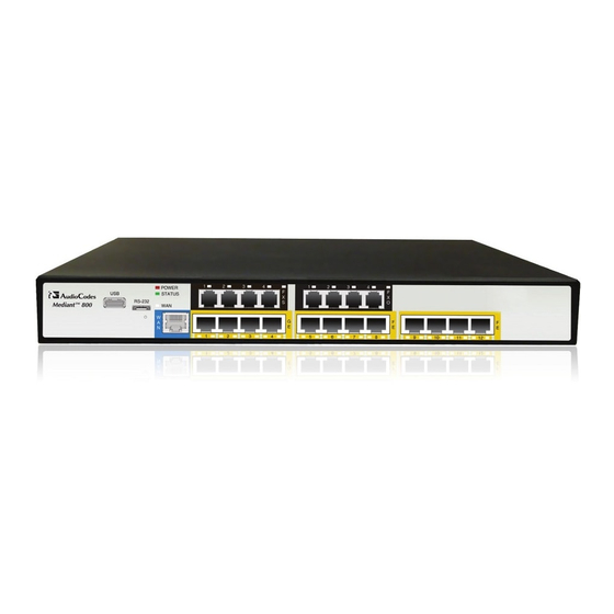
Page 14: Table 3-2: Front Panel Description
Mediant 800 MSBR Table 3-2: Front Panel Description Item # Label Description USB/WWAN USB port for connecting an optional 3G cellular WAN modem (for primary or backup WAN), or an external USB hard drive or flash disk (disk on key) for USB storage capabilities. -
Page 15: Leds
Hardware Installation Manual 3. Physical Description Item # Label Description Eight Fast Ethernet (10/100Base-TX) RJ-45 LAN ports for connecting IP phones, computers, or switches. These ports support half- and full- duplex modes, auto-negotiation, and straight or crossover cable detection. These ports also support PoE, complying with the IEEE 802.3af-2003 standard. -
Page 16: Wi-Fi Led
Mediant 800 MSBR 3.2.2.3 Wi-Fi LED The Wi-Fi LED indicates the Wi-Fi link status, as described in the table below. Table 3-5: Wi-Fi LED Description LED Color LED State Description Wi-Fi is activated. Flashing Traffic on the wireless LAN. Wi-Fi is not configured. -
Page 17: Fxo Led
Hardware Installation Manual 3. Physical Description 3.2.2.6 FXO LED Each FXO port provides a LED for indicating operating status, as described in the table below. Table 3-8: FXO LED Description Description Color State Green FXO line is off-hooked toward the PBX. Flashing Ring signal detected from the PBX. -
Page 18: Operational Status Led
Mediant 800 MSBR 3.2.2.9 Operational Status LED The STATUS LED indicates the operating status, as described in the table below. Table 3-11: STATUS LED Description Description Color State Green The device is operational. Flashing The device is rebooting. Boot failure. -
Page 19: Rear Panel Description
Hardware Installation Manual 3. Physical Description Rear Panel Description The device's rear panel is shown in the figure below and described in the subsequent table. Figure 3-2: Rear Panel Note: The figure above is used only as an example. The OSN server ports and Wi-Fi interface are available only if customer ordered. -
Page 20: Table 3-13: Rear Panel Description
Mediant 800 MSBR Table 3-13: Rear Panel Description Item # Label Description OSN USB Three USB ports (Standard-A type) for connecting computer peripherals (e.g., mouse and keyboard). These are used when implementing the OSN. Note: These ports are available only if the device is equipped with the OSN server (customer ordered). -
Page 21: Attaching The Wi-Fi Antennas
Hardware Installation Manual 4. Attaching the Wi-Fi Antennas Attaching the Wi-Fi Antennas For models ordered with wireless LAN interface, the device is shipped with three unattached Wi-Fi antennas. You can attach any number of these antennas, according to your network requirements. Once attached, you can position each antenna in the vertical and/or horizontal plane for optimal transmission and reception. - Page 22 Mediant 800 MSBR Orient the antennas as desired for optimal wireless performance. The antenna can be orientated in the vertical and horizontal planes. For best performance, it is recommended that the antennas be perpendicular (90 degrees) to the floor. In other words: •...
-
Page 23: Mounting The Device
Hardware Installation Manual 5. Mounting the Device Mounting the Device The device can be mounted in one of the following ways: Placed on a desktop – see Section on page Installed in a standard 19-inch rack – see Section on page ... -
Page 24: 19-Inch Rack Mounting
Mediant 800 MSBR 19-Inch Rack Mounting The device can be installed in a standard 19-inch rack by implementing one of the following mounting methods: Placing it on a pre-installed shelf in a 19-inch rack – see Section 5.2.1 on page ... -
Page 25: Using Mounting Brackets
Hardware Installation Manual 5. Mounting the Device 5.2.2 Using Mounting Brackets The procedure below describes how to mount the device in a 19-inch rack. Rack mounting involves placing the device on a pre-installed rack shelf and then attaching the device's mounting brackets (to the device and rack frame). - Page 26 Mediant 800 MSBR Reader's Notes Hardware Installation Manual Document #: LTRT-10208...
-
Page 27: Cabling The Device
Hardware Installation Manual 6. Cabling the Device Cabling the Device This section describes the cabling of the device, which includes the following: Grounding (earthing) the device – see Section on page Connecting to the WAN – see Section on page ... -
Page 28: Connecting To Wan
Mediant 800 MSBR Connecting to WAN This section provides a description on how to cable the WAN port. The cabling procedure depends on the ordered WAN interface: Gigabit Ethernet (GbE) – see Section 6.2.1 on page SHDSL – see Section 6.2.2... -
Page 29: Shdsl Wan Cabling
Hardware Installation Manual 6. Cabling the Device Signal Name Ethernet signal pair Shield Chassis ground 6.2.2 SHDSL WAN Cabling The SHDSL port has four wire-pairs, supporting up to four SHDSL WAN ports on a single physical connector (RJ-45). SHDSL port specifications: Conforms to ITU G.991.2 Annexes A, B, E, F and G SHDSL ... -
Page 30: Adsl And Vdsl Wan Cabling
Mediant 800 MSBR Function CH1-TIP CH1-RING CH2-TIP CH2-RING CH3-TIP CH3-RING 6.2.3 ADSL and VDSL WAN Cabling The ADSL/VDSL WAN port provides a single ADSL/VDSL interface through its RJ-45 port. The specifications of the ADSL/VDSL interface include the following: ADSL (ATM): ... -
Page 31: Table 6-3: Rj-45 Connector Pinouts For Adsl/Vdsl
Hardware Installation Manual 6. Cabling the Device Note: The ADSL filter/splitter should be provided by your service provider. The cable connector pinouts are described in the table below: Table 6-3: RJ-45 Connector Pinouts for ADSL/VDSL Function CH0-TIP CH0-RING Not connected Not connected Not connected Not connected... -
Page 32: 3G/3.5G Cellular Wan Usb Modem Cabling
Mediant 800 MSBR 6.2.4 3G/3.5G Cellular WAN USB Modem Cabling The device supports 3G cellular WAN connection using a USB modem. The 3G cellular WAN interface can be used as the primary WAN interface or as an optional WAN backup when the primary WAN (e.g., WAN Ethernet) fails. -
Page 33: Figure 6-6: Connecting The Lan Ports
Hardware Installation Manual 6. Cabling the Device Signal Name Ethernet signal pair (1000Base-T) Ethernet signal pair (1000Base-T) Shield Chassis ground To connect the device to the LAN: Connect one end of a straight-through RJ-45 Cat 5e or Cat 6 cable to the RJ-45 port labeled GE (for Gigabit Ethernet ports) and/or FE (for Fast Ethernet ports). -
Page 34: Connecting Poe-Enabled Clients To Lan Ports
Mediant 800 MSBR Connecting PoE-Enabled Clients to LAN Ports The LAN ports support PoE according to the IEEE 802.3af-2003 standard. The ports can transfer electrical power, along with the usual data, over the Ethernet cable to connected equipment (e.g., IP phone) capable of receiving PoE. -
Page 35: Fxs Interfaces
Hardware Installation Manual 6. Cabling the Device FXS Interfaces The procedure below describes how to cable the device's FXS interfaces. Warnings: • Ensure that the FXS ports are connected to the appropriate, external devices; otherwise, damage to the device may occur. •... -
Page 36: Connecting To Analog Devices
Mediant 800 MSBR 6.5.1 Connecting to Analog Devices The procedure below describes how to cable the device's FXO interfaces. Warnings: • To protect against electrical shock and fire, use a minimum 26-AWG wire to connect FXO ports to the PSTN. -
Page 37: Connecting The Analog Lifeline
Hardware Installation Manual 6. Cabling the Device 6.5.2 Connecting the Analog Lifeline The device's analog Lifeline phone feature redirects IP calls to the PSTN upon a power outage or loss of IP network connectivity, thereby guaranteeing call continuity. The Lifeline is provided by FXS Port # 1. -
Page 38: Isdn Bri Interfaces
Mediant 800 MSBR ISDN BRI Interfaces 6.6.1 Connecting to BRI Lines The device provides up to four BRI S/T ports. These ports connect to ISDN terminal equipment such as ISDN telephones. Each BRI port can be configured either as termination equipment/user side (TE) or network termination/network side (NT). -
Page 39: Connecting The Pstn Fallback For Bri Lines
Hardware Installation Manual 6. Cabling the Device 6.6.2 Connecting the PSTN Fallback for BRI Lines The device supports a PSTN Fallback feature for BRI lines, whereby if a power outage or IP connectivity problem (e.g., no ping) occurs, IP calls are re-routed to the PSTN. This guarantees call continuity. -
Page 40: Connecting Isdn Pri (E1/T1) Trunks
Mediant 800 MSBR Connecting ISDN PRI (E1/T1) Trunks The procedure below describes the cabling of the device's E1/T1 trunk. Warning: To protect against electrical shock and fire, use a 26 AWG min wire to connect T1 or E1 ports to the PSTN. -
Page 41: Connecting The Serial Interface To A Pc
Hardware Installation Manual 6. Cabling the Device Connecting the Serial Interface to a PC The device provides an RS-232 serial interface port on its front panel. The serial cable adapter used for connecting the RS-232 interface is shown below: Figure 6-18: RS-232 Cable Adapter To connect the device's serial interface port to a PC: ... -
Page 42: Connecting A Usb Storage Device
Mediant 800 MSBR Connecting a USB Storage Device The device supports USB storage capabilities, using an external USB hard drive or flash disk (disk on key) connected to the device's USB port. The storage capabilities include the following: Saving network captures to the USB. This is done using the following CLI command: ... -
Page 43: Connecting The Osn Server
Ethernet ports on the rear panel, you can use the LAN port #1 located on the front panel for connecting to the OSN server. • If your device is shipped with an OSN server, you can download the latest OSN drivers from AudioCodes Web site at http://www.audiocodes.com/downloads. To connect the OSN server: ... -
Page 44: Connecting To A Power Supply
Mediant 800 MSBR Connect the device to power. Insert the operating system CD media (Linux or Microsoft Windows) into the CD-ROM drive. Continue according to the CD's installation instructions. To reset the OSN server: Insert a sharp-pointed object (such as a drawing pin) into the Reset pinhole and then ... -
Page 45: Figure 7-1: Opening The Fuse Cavity
Hardware Installation Manual 7. Maintenance – Replacing the Power Fuse Maintenance – Replacing the Power Fuse The device contains a fuse that protects the device from excessive current. The fuse is located on the rear panel, below the power socket. To replace the fuse, use only one of the following fuses described in the table below: Table 7-1: Allowed Fuses for the Device Manufacturer... - Page 46 Mediant 800 MSBR Reader's Notes Hardware Installation Manual Document #: LTRT-10208...
- Page 47 For CentOS to identify the OSN server’s Gigabit Ethernet (GE) interfaces, do the following: Obtain the following files from AudioCodes: Binary compiled CentOS 4.7 driver for Intel e1000e Ethernet controller on ♦ Mediant 800 MSBR (e1000e.ko) Manual pages (e1000e.7.gz) ♦...
- Page 48 Hardware Installation Manual www.audiocodes.com...