AudioCodes Mediant 800 MSBR Hardware Installation Manual
Multi-service business routers
Hide thumbs
Also See for Mediant 800 MSBR:
- User manual (1002 pages) ,
- Hardware installation manual (72 pages) ,
- Configuration manual (74 pages)
Table of Contents
Advertisement
Quick Links
Download this manual
See also:
User Manual
Advertisement
Table of Contents

Related Manuals for AudioCodes Mediant 800 MSBR


Summary of Contents for AudioCodes Mediant 800 MSBR
- Page 1 Hardware Installation Manual AudioCodes Multi-Service Business Routers (MSBR) Mediant™ 800 MSBR...
-
Page 3: Table Of Contents
Connecting the PSTN Fallback for BRI Lines ............49 Connecting to ISDN PRI (E1/T1) Trunks ..............50 Connecting the Serial Interface to a PC ..............51 Connecting a USB Storage Device ................ 54 6.10 Connecting the OSN Server ................... 55 MSBR Series Mediant 800 MSBR... - Page 4 Mediant 800 MSBR 6.11 Connecting to Power ....................57 Maintenance ...................... 59 Replacing the Power Fuse ..................59 A Approved Laser SFPs ..................61 B Notice for Installing CentOS Version 4.7 on OSN Server ......63 Hardware Installation Manual Document #: LTRT-10229...
- Page 5 Figure 6-24: Orderable RS-232 Cable Adapter ..................52 Figure 6-25: Cabling Serial Interface (RJ-45) on Mediant 800B MSBR ..........53 Figure 6-26: Cabling Serial Interface (12-pin female LX40-12P Hirose) on Mediant 800 MSBR ..53 Figure 6-27: Connecting USB Storage Device ..................54 Figure 6-28: Cabling OSN Server Ports ....................
- Page 6 Mediant 800 MSBR List of Tables Table 3-1: Physical Dimensions ......................15 Table 3-2: Front-Panel Description of Ports and Buttons ..............16 Table 3-3: LAN LED Description ......................19 Table 3-4: PoE LAN LED Description ....................19 Table 3-5: Wi-Fi LED Description ......................19 Table 3-6: GE WAN LED Description ....................
-
Page 7: Weee Eu Directive
Customer Support Customer technical support and services are provided by AudioCodes or by an authorized AudioCodes Service Partner. For more information on how to buy technical support for AudioCodes products and for contact information, please visit our Web site at https://www.audiocodes.com/services-support/maintenance-and-support. -
Page 8: Related Documentation
Mediant 800 MSBR Related Documentation Document Name SIP Release Notes Mediant 800 MSBR SIP User's Manual CLI Reference Guide Notes and Warnings Warning: The device is an INDOOR unit and therefore, must be installed only indoors. Note: Open source software may have been added and/or amended for this product. For further information, please visit our website at http://audiocodes.com/support... -
Page 9: Document Revision Record
10228 Typo fixed re 19-inch rack mounting brackets. 10229 Logo updated; Documentation Feedback AudioCodes continually strives to produce high quality documentation. If you have any comments (suggestions or errors) regarding this document, please fill out the Documentation Feedback form site https://online.audiocodes.com/documentation-feedback. - Page 10 Mediant 800 MSBR This page is intentionally left blank. Hardware Installation Manual Document #: LTRT-10229...
-
Page 11: Introduction
Hardware Installation Manual 1. Introduction Introduction This document provides a hardware description of the Mediant 800 MSBR (hereafter referred to as device) and step-by-step procedures for mounting and cabling the device. The device provides the following interfaces: Optional telephony interfaces: •... - Page 12 Mediant 800 MSBR This page is intentionally left blank. Hardware Installation Manual Document #: LTRT-10229...
-
Page 13: Unpacking The Device
E1/T1 WAN interface (only for devices ordered with a single E1/T1 WAN port) • Serial cable adapter • One AC power cable Check, retain and process any documents. If there are any damaged or missing items, notify your AudioCodes sales representative. MSBR Series Mediant 800 MSBR... - Page 14 Mediant 800 MSBR This page is intentionally left blank. Hardware Installation Manual Document #: LTRT-10229...
-
Page 15: Physical Description
Mediant 800B; the previous version is referred to as Mediant 800A. The shipped chassis version depends on your ordered hardware configuration. For more information, contact your AudioCodes sales representative. In addition, throughout this manual, the Mediant 800B is used in illustrations, unless specific instructions are necessary for the Mediant 800A chassis. -
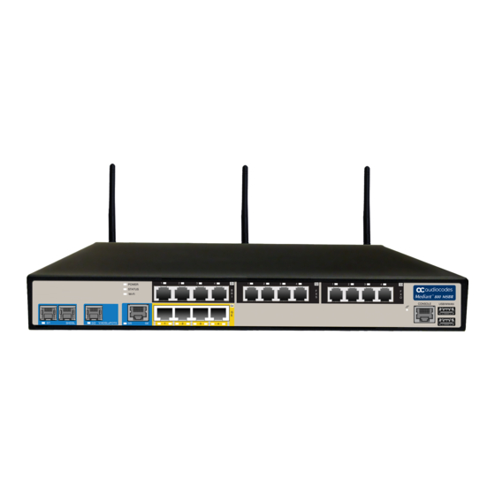
Page 16: Front Panel Description
The figures above are used only as examples; the number and type of port interfaces depends on the ordered model. • For available hardware configurations, please contact your AudioCodes sales representative. Table 3-2: Front-Panel Description of Ports and Buttons Item #... - Page 17 GE (Copper GbE) / (Optional) One or two additional WAN interfaces. Below is a partial list of currently supported configurations. For a full list of supported V/ADSLoPOTS / WAN configurations, contact your AudioCodes sales representative. SHDSL / One copper GE GE SFP (Optic Fiber) ...
- Page 18 Mediant 800 MSBR Item # Label Description model). Note: PoE support is a customer ordered feature. (Optional) Eight Fast Ethernet (10/100Base-TX) RJ-45 LAN ports for connecting IP phones, computers, or switches. These ports support half- and full-duplex modes, auto-negotiation, and straight or crossover cable detection.
-
Page 19: Leds
The Wi-Fi LED indicates the Wi-Fi link status, as described in the table below. Table 3-5: Wi-Fi LED Description LED Color LED State Description Green Wi-Fi is activated. Flashing Traffic on the wireless LAN. Wi-Fi is not configured. MSBR Series Mediant 800 MSBR... -
Page 20: Wan Leds
Mediant 800 MSBR 3.2.2.4 WAN LEDs 3.2.2.4.1 GE WAN LED The WAN GE port provides a LED for indicating operating status, as described in the table below. Table 3-6: GE WAN LED Description Description Color State Green WAN link established. -
Page 21: Table 3-9: A/Vdsl Wan Led Description
The WAN SFP LED indicates the status of the optical fiber WAN link, as described in the table below. Table 3-10: WAN SFP LED Description Description Color State Green WAN fiber link established. Flashing Data is being received or transmitted. No WAN fiber link or power not received by the device. MSBR Series Mediant 800 MSBR... -
Page 22: Fxs Led
Mediant 800 MSBR 3.2.2.5 FXS LED Each FXS port provides a LED for indicating operating status, as described in the table below. Table 3-11: FXS LED Description Description Color State Green Phone is off-hooked. Flashing Rings the extension line. ... -
Page 23: E1/T1 Led
The POWER LED indicates the power supply status, as described in the table below. Table 3-16: POWER LED Description Description Color State Green Power is received by the device. No power received by the device. MSBR Series Mediant 800 MSBR... -
Page 24: Rear Panel Description
Mediant 800 MSBR Rear Panel Description The device's rear panel is shown in the figure below and described in the subsequent table. Figure 3-3: Rear Panel Note: The figure above is used only as an example. The OSN server ports and Wi-Fi antennas are customer ordered items. - Page 25 2.4 GHz and 5 GHz Tx / Rx, enabling data rates of up to 300 Mbps. The Wi-Fi interface also supports 802.11b/802.11g backward compatibility, allowing interoperability of multiple devices with different types of Wi-Fi. Note: The Wi-Fi antennas are available (shipped un-attached) only if Wi-Fi functionality is ordered. MSBR Series Mediant 800 MSBR...
- Page 26 Mediant 800 MSBR This page is intentionally left blank. Hardware Installation Manual Document #: LTRT-10229...
-
Page 27: Attaching The Wi-Fi Antennas
Orient the antennas as desired for optimal wireless performance. The antenna can be orientated in the vertical and horizontal planes. For best performance, it is recommended that the antennas be perpendicular (90 degrees) to the floor. In other words, orient the antennas straight up. MSBR Series Mediant 800 MSBR... - Page 28 Mediant 800 MSBR This page is intentionally left blank. Hardware Installation Manual Document #: LTRT-10229...
-
Page 29: Mounting The Device
Peel off the adhesive, anti-slide rubber feet and stick one in each anti-slide groove. Figure 5-1: Location for Applying Rubber Feet Flip the device over again so that it rests on the rubber feet and place it in the required position on a desktop. MSBR Series Mediant 800 MSBR... -
Page 30: 19-Inch Rack Mounting
Mediant 800 MSBR 19-Inch Rack Mounting The device can be installed in a standard 19-inch rack by implementing one of the following mounting methods: Placing it on a pre-installed shelf in a 19-inch rack – see Section 5.2.1 on page ... -
Page 31: Using Mounting Brackets
Place the device on a pre-installed shelf in the rack. Attach the ends of the mounting brackets (that you installed in Step 1) to the vertical track of the rack's frame, using standard 19-inch rack bolts (not supplied). MSBR Series Mediant 800 MSBR... - Page 32 Mediant 800 MSBR This page is intentionally left blank. Hardware Installation Manual Document #: LTRT-10229...
-
Page 33: Cabling The Device
The equipment is classified as Class I EN60950 and UL60950 and must be earthed at all times. For Finland: "Laite on liltettava suojamaadoituskoskettimilla varustettuun pistorasiaan." For Norway: "Apparatet rna tilkoples jordet stikkontakt." For Sweden: "Apparaten skall anslutas till jordat uttag." MSBR Series Mediant 800 MSBR... -
Page 34: Figure 6-1: Earthing The Device
• As most of the installation is the responsibility of the customer, AudioCodes can assume responsibility for damage only if the customer can establish that the device does not comply with the standards specified above (and the device is within the hardware warranty period). -
Page 35: Connecting To Wan
Cable: Cat 5 Ethernet cable Connector: RJ-45 Connector Pinouts: Table 6-1: RJ-45 Connector Pinouts for Copper GbE WAN Signal Name Ethernet signal pair Ethernet signal pair Ethernet signal pair Ethernet signal pair Shield Chassis ground MSBR Series Mediant 800 MSBR... -
Page 36: Fiber-Optic Gigabit Ethernet Cabling
Note that SFP modules and fiber-optic cables are not supplied. It is recommended that you purchase the SFP modules from AudioCodes. For a list of orderable SFP modules, see Appendix on page 61, or contact your AudioCodes sales representative. -
Page 37: Shdsl Wan Cabling
Up to 5,696 Kbps over a single wire pair Up to 22,784 Kbps over four wire pairs bonding, according to SHDSL.bis (ITU G.991.2 Annexes F, G) EFM and ATM support Wetting current support on the CPE side, according to G991.2 MSBR Series Mediant 800 MSBR... -
Page 38: Figure 6-5: Cabling The Shdsl Wan Port
Mediant 800 MSBR Supports both Central Office (CO) and CPE (wetting current on CO - excluded) TC-PAM 16/32 line code Cable specification: Cable: 26-AWG min. wire Connector: RJ-11 Connector Pinouts: Table 6-2: RJ-11 Connector Pinouts for SHDSL... -
Page 39: Adsl/2+ And Vdsl2 Wan Cabling
DSL ports. Cable specifications: Cable: 26-AWG min. wire Connector: RJ-11 or RJ-45 Connector Pinouts: Table 6-3: RJ-11 Connector Pinouts for xDSL Function Not used Not used CH0-P/Tip CH0-N/Ring Not used Not used MSBR Series Mediant 800 MSBR... -
Page 40: Figure 6-6: Cabling Xdsl Wan Port
Mediant 800 MSBR Table 6-4: RJ-45 Connector Pinouts for xDSL Function Not used Not used Not used CH0-P/Tip CH0-N/Ring Not used Not used Not used To connect the WAN xDSL WAN port: Connect an RJ-11 or RJ-45 cable connector to the device’s xDSL WAN port (labeled V/ADSLoISDN). -
Page 41: E1/T1 Wan Cabling
Connect the RJ-45 connector on one end of the cable to the E1/T1 WAN port, labeled T1E1. Figure 6-9: Connecting the E1/T1 WAN Port Connect the other end of the cable to the E1 or T1 line. MSBR Series Mediant 800 MSBR... -
Page 42: 3.5G Cellular Wan Usb Modem Cabling
(PPP) over cellular. Note: To verify whether your third-party, 3G cellular modem is supported by the device, please provide the modem's model details to your AudioCodes sales representative. To connect the 3G cellular WAN modem: ... -
Page 43: Connecting To Lan
GE (for Gigabit Ethernet ports) and/or FE (for Fast Ethernet ports). Figure 6-11: Cabling the LAN Ports Connect the other end of the cable to the Gigabit Ethernet network (for the GE ports) and/or Fast Ethernet network (for the FE ports). MSBR Series Mediant 800 MSBR... -
Page 44: Connecting Poe-Enabled Clients To Lan Ports
Mediant 800 MSBR Connecting PoE-Enabled Clients to LAN Ports The LAN ports support PoE according to the IEEE 802.3af-2003 and IEEE 802.3at standards. The ports can transfer electrical power, along with the usual data, over the Ethernet cable to connected equipment (e.g., IP phone) capable of receiving PoE. -
Page 45: Analog Interfaces
Connect one end of an RJ-11 cable to the FXS port (labeled FXS). Figure 6-13: Connecting FXS Interfaces Connect the other end of the cable to the required telephone interface (e.g., fax machine, dial-up modem, and analog POTS telephone). MSBR Series Mediant 800 MSBR... -
Page 46: Connecting Fxo Interfaces
Mediant 800 MSBR 6.5.2 Connecting FXO interfaces The procedure below describes how to cable the device's FXO interfaces. Warnings: • The device does not include primary telecom protection! When the FXO telephone lines are routed outside the building, additional protection - usually a 350V three- electrode Gas Discharge Tube (GDT) as described in ITU-T K.44 - must be provided... -
Page 47: Connecting The Fxs Analog Lifeline
Analog Lifeline cabling is applicable only if the device is ordered with FXS interfaces. • The number of supported Lifelines depends on the device’s hardware configuration. For the combined FXS/FXO configuration, one Lifeline is available; for the 12-FXS configuration, up to three Lifelines are available. MSBR Series Mediant 800 MSBR... -
Page 48: Isdn Bri Interfaces
Mediant 800 MSBR ISDN BRI Interfaces 6.6.1 Connecting to BRI Lines The device provides up to four BRI S/T ports. These ports connect to ISDN terminal equipment such as ISDN telephones. Each BRI port can be configured either as termination equipment/user side (TE) or network termination/network side (NT). -
Page 49: Connecting The Pstn Fallback For Bri Lines
PSTN Fallback is supported only on the BRI module. • PSTN Fallback is supported only between ports on the same BRI module. • This PSTN Fallback feature has no relation to the PSTN Fallback Software Upgrade Key. MSBR Series Mediant 800 MSBR... -
Page 50: Connecting To Isdn Pri (E1/T1) Trunks
Mediant 800 MSBR Connecting to ISDN PRI (E1/T1) Trunks The procedure below describes how to cable the device's E1/T1 trunk. Warning: • PRI port cabling must be routed only indoors and must not exit the building. • To protect against electrical shock and fire, use a 26 AWG min wire to connect T1 or E1 ports to the PSTN. -
Page 51: Connecting The Serial Interface To A Pc
• Cable: RJ-45 to DB-9 The serial cable adapter used for connecting the RS-232 interface is shown below: Figure 6-23: RS-232 Cable Adapter Table 6-6: RJ-45 to DB-9 Serial Cable Connector Pinouts RJ-45 DB-9 Female MSBR Series Mediant 800 MSBR... -
Page 52: Figure 6-24: Orderable Rs-232 Cable Adapter
Port Type: 12-pin female LX40-12P Hirose connector • Cable: Can be purchased from AudioCodes - RS-232 cable adapter (9-pin DB to flat connector). The Customer Product Number is PicoBlade-Serial. This orderable item is supplied in a kit of 10 cables. The figure below displays this cable adapter, where "P1"... -
Page 53: Figure 6-25: Cabling Serial Interface (Rj-45) On Mediant 800B Msbr
Connect the red 9-pin DB connector ("P1") on the other end of the cable, to the COM1 or COM2 RS-232 communication port on your PC. Figure 6-26: Cabling Serial Interface (12-pin female LX40-12P Hirose) on Mediant 800 MSBR MSBR Series... -
Page 54: Connecting A Usb Storage Device
Mediant 800 MSBR Connecting a USB Storage Device The device supports USB storage capabilities, using an external USB hard drive or flash disk (disk on key) connected to the device's USB port. The storage capabilities include the following: Saving network captures to the USB. -
Page 55: Connecting The Osn Server
• If your device is shipped with an OSN server, you can download the latest OSN drivers from AudioCodes Web site at http://www.audiocodes.com/downloads. • The table above lists the currently available OSN platforms. This list may change without notice. To check for any updated information on available OSN platforms, contact your AudioCodes sales representative. -
Page 56: Figure 6-28: Cabling Osn Server Ports
Mediant 800 MSBR To connect the OSN server: Perform the following cabling procedures on the OSN server, located on the rear panel: Connect computer peripherals (e.g., mouse and keyboard) to the USB ports (Standard-A type) labeled USB. Connect the USB storage device containing the operating system installation files (Linux or Microsoft Windows) to one of the USB ports, labeled USB. -
Page 57: Connecting To Power
Use only the AC power cord that is supplied with the device. • For replacing the power fuse, see Section on page 59. ご注 意 本製品に添付の電源ケーブルは、Mediant 800 MSBR に専用設計されているため、汎用性がありません. 本電源ケーブルを他の機器に使用されないよう、ご注意ください. To connect the device to the power supply: Connect the line socket of the AC power cord (supplied) to the device's AC power socket (labeled 100-240V 1.5A ~50-60 Hz), located on the rear panel. - Page 58 Mediant 800 MSBR This page is intentionally left blank. Hardware Installation Manual Document #: LTRT-10229...
-
Page 59: Maintenance
Using a small flathead screwdriver, gently pries open the fuse cavity as illustrated in the figure below: Figure 7-1: Opening the Fuse Cavity Carefully remove the fuse from the fuse cavity. Figure 7-2: Removing the Power Fuse MSBR Series Mediant 800 MSBR... - Page 60 Mediant 800 MSBR Insert the new fuse securely into the fuse cavity until you hear a click sound. Reconnect the power cord and verify that the Power LED is lit green. Hardware Installation Manual Document #: LTRT-10229...
-
Page 61: A Approved Laser Sfps
Hardware Installation Manual A. Approved Laser SFPs Approved Laser SFPs The table below lists the recommended SFPs, which can be ordered from AudioCodes. For installing the SFPs and for fiber-optic WAN cabling, see Section 6.2.2 on page 36. Table A-1: Approved SFP Modules... - Page 62 Mediant 800 MSBR This page is intentionally left blank. Hardware Installation Manual Document #: LTRT-10229...
-
Page 63: B Notice For Installing Centos Version 4.7 On Osn Server
When installing CentOS, ensure that you type linux irqpoll at the boot: prompt. For CentOS to identify the OSN server’s Gigabit Ethernet (GE) interfaces, do the following: Obtain the following files from AudioCodes: ♦ Binary compiled CentOS 4.7 driver for Intel e1000e Ethernet controller on Mediant 800 MSBR (e1000e.ko) ♦... - Page 64 Website: ©2017 AudioCodes Ltd. All rights reserved. AudioCodes, AC, HD VoIP, HD VoIP Sounds Better, IPmedia, Mediant, MediaPack, What’s Inside Matters, OSN, SmartTAP, User Management Pack, VMAS, VoIPerfect, VoIPerfectHD, Your Gateway To VoIP, 3GX, VocaNom, AudioCodes One Voice and CloudBond are trademarks or registered trademarks of AudioCodes Limited.