AudioCodes Mediant 500 MSBR Hardware Installation Manual
Multi-service business router, enterprise session border controller
Hide thumbs
Also See for Mediant 500 MSBR:
- User manual (1248 pages) ,
- Configuration manual (74 pages) ,
- Hardware installation manual (56 pages)
Table of Contents
Advertisement
Quick Links
Download this manual
See also:
User Manual
Advertisement
Table of Contents

Related Manuals for AudioCodes Mediant 500 MSBR


Summary of Contents for AudioCodes Mediant 500 MSBR
- Page 1 Mediant™ 500 MSBR Multi-Service Business Router Enterprise Session Border Controller Hardware Installation Manual Version 6.8 December 2013 Document #: LTRT-10323...
-
Page 3: Table Of Contents
Connecting the FXS Analog Lifeline ............... 38 Connecting the Serial Interface to a PC ..............39 Connecting a USB Storage Device ................ 40 Connecting to a Power Supply ................41 A Approved Laser SFPs ..................43 Version 6.8 Mediant 500 MSBR... - Page 4 Mediant 500 MSBR List of Figures Figure 3-1: Front Panel .......................... 13 Figure 3-2: Rear Panel .......................... 18 Figure 4-1: Attaching Antennas on Rear Panel ..................19 Figure 5-1: Location for Applying Rubber Foot ..................21 Figure 5-2: Left Mounting Bracket ......................23 Figure 5-3: Right Mounting Bracket .......................
- Page 5 Table 6-2: RJ-11 Connector Pinouts for xDSL ..................29 Table 6-3: RJ-45 Connector Pinouts for GbE ..................31 Table 6-4: RJ-45 to DB-9 Serial Cable Connector Pinouts ..............39 Table A-1: Approved SFP Modules ....................... 43 Version 6.8 Mediant 500 MSBR...
- Page 6 Mediant 500 MSBR Reader's Notes Hardware Installation Manual Document #: LTRT-10323...
- Page 7 This document is subject to change without notice. Date Published: December-19-2013 Trademarks AudioCodes, AC, AudioCoded, Ardito, CTI2, CTI², CTI Squared, HD VoIP, HD VoIP Sounds Better, InTouch, IPmedia, Mediant, MediaPack, NetCoder, Netrake, Nuera, Open Solutions Network, OSN, Stretto, TrunkPack, VMAS, VoicePacketizer, VoIPerfect, VoIPerfectHD, What’s Inside Matters, Your Gateway To VoIP and 3GX are trademarks or...
- Page 8 Mediant 500 MSBR Related Documentation Document Name SIP Release Notes Mediant 500 MSBR SIP User's Manual CLI Reference Guide General Notes and Warnings, and Safety Information Note: Open source software may have been added and/or amended for this product. For further information, please visit our website at http://audiocodes.com/support...
-
Page 9: Introduction
Hardware Installation Manual 1. Introduction Introduction This document provides a hardware description of the Mediant 500 MSBR (hereafter referred to as device) and step-by-step procedures for mounting and cabling the device. The device supports the following interfaces: Multiple WAN: ... - Page 10 Mediant 500 MSBR Reader's Notes Hardware Installation Manual Document #: LTRT-10323...
-
Page 11: Unpacking The Device
Two Wi-Fi antennas (depending on ordered model) • Serial cable adapter • One AC power cable Check, retain and process any documents. If there are any damaged or missing items, notify your AudioCodes sales representative. Version 6.8 Mediant 500 MSBR... - Page 12 Mediant 500 MSBR Reader's Notes Hardware Installation Manual Document #: LTRT-10323...
-
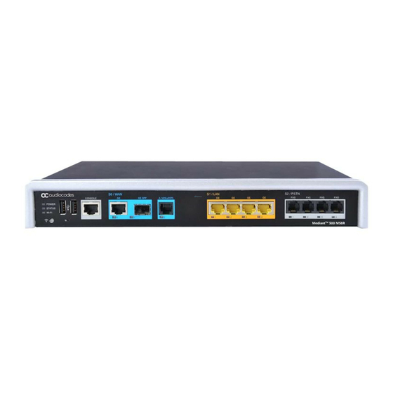
Page 13: Physical Description
The device's front panel is shown in the figure below and described in the subsequent table. Figure 3-1: Front Panel Note: The figure above is used only as an example. The hardware configuration depends on the ordered model. Version 6.8 Mediant 500 MSBR... -
Page 14: Table 3-2: Front Panel Description
SFP module (single pair, supporting 1 GbE) ADSL/2+ and VDSL2 Note: For available WAN configurations, contact your AudioCodes sales representative. Up to four Gigabit Ethernet (10/100/1000Base-T) ports for connecting to LAN network (IP phones, computers, or switches). These ports support half- and full-duplex modes, auto-negotiation, and straight or crossover cable detection. -
Page 15: Leds
The Wi-Fi LED indicates the Wi-Fi link status, as described in the table below. Table 3-5: Wi-Fi LED Description LED Color LED State Description Wi-Fi is activated. Green Flashing Traffic on the wireless LAN. Wi-Fi is not configured. Version 6.8 Mediant 500 MSBR... -
Page 16: E1/T1 Led
Mediant 500 MSBR 3.2.2.4 E1/T1 LED The trunk port provides a LED for indicating operating status, as described in the table below: Table 3-6: E1/T1 LED Description Color State Description Green Trunk is synchronized (normal operation). Loss due to any of the following signals: ... -
Page 17: Fxo Led
Power LED The POWER LED indicates the operating status, as described in the table below. Table 3-11: POWER LED Description Description Color State Green Power is received by the device. No power received by the device. Version 6.8 Mediant 500 MSBR... -
Page 18: Rear Panel Description
Mediant 500 MSBR Rear Panel Description The device's rear panel is shown in the figure below and described in the subsequent table. Figure 3-2: Rear Panel Note: The figure above is used only as an example. The Wi-Fi antennas are available only if customer ordered. -
Page 19: Attaching The Wi-Fi Antennas
Orient the antennas as desired for optimal wireless performance. The antenna can be orientated in the vertical and horizontal planes. For best performance, it is recommended that the antennas be perpendicular (90 degrees) to the floor. In other words, orient the antennas straight up. Version 6.8 Mediant 500 MSBR... - Page 20 Mediant 500 MSBR Reader's Notes Hardware Installation Manual Document #: LTRT-10323...
-
Page 21: Mounting The Device
• 1 = Mounted anti-slide rubber feet • 2 = Anti-slide groove Flip the device over again so that it rests on the rubber feet and place it in the required position on a desktop. Version 6.8 Mediant 500 MSBR... -
Page 22: 19-Inch Rack Mounting
Mediant 500 MSBR 19-Inch Rack Mounting The device can be installed in a standard 19-inch rack by implementing one of the following mounting methods: Placing it on a pre-installed shelf in a 19-inch rack – see Section 5.2.1 on page ... -
Page 23: Using Mounting Brackets
Figure 5-2: Left Mounting Bracket Right mounting bracket with hole for looping through an optional cable tie (not supplied) for securing cables: Figure 5-3: Right Mounting Bracket Note: The mounting brackets for 19-inch rack mounting are customer-ordered items. Version 6.8 Mediant 500 MSBR... -
Page 24: Figure 5-4: Attaching The Mounting Brackets
Mediant 500 MSBR To mount the device in a 19-inch rack using mounting brackets: Attach the two mounting brackets (supplied) to each side of the device's chassis, using the supplied screws, as shown in the figure below: Figure 5-4: Attaching the Mounting Brackets •... -
Page 25: Cabling The Device
(located on the rear panel), using the supplied washer. Connect the other end of the strap to a protective earthing. This should be in accordance with the regulations enforced in the country of installation. Figure 6-1: Earthing the Device Version 6.8 Mediant 500 MSBR... -
Page 26: Connecting To Wan
Mediant 500 MSBR Connecting to WAN This section provides a description on how to cable the WAN port. The cabling procedure depends on the ordered WAN interface: Copper Gigabit Ethernet (GbE) – see Section 6.2.1 on page Fiber-optic GbE – see Section 6.2.2... -
Page 27: Fiber-Optic Gigabit Ethernet Cabling
Note that SFP modules and fiber-optic cables are not supplied. It is recommended that you purchase the SFP modules from AudioCodes. For a list of orderable SFP modules, see Appendix on page 43, or contact your AudioCodes sales representative. -
Page 28: Adsl/2+ And Vdsl2 Wan Cabling
Mediant 500 MSBR The procedure below describes how to connect the ports over fiber-optic cables. To connect the fiber-optic WAN GbE port: Remove the protective dust plug from the SFP transceiver module. Figure 6-3: Removing Protective Dust Plug Connect a cable with LC-type plugs to the SFP transceivers (labeled GE SFP). -
Page 29: Figure 6-5: Cabling The Xdsl Wan Port
Connect an RJ-11 cable connector to the device’s xDSL WAN port (labeled V/ADSLoPOTS). Figure 6-5: Cabling the xDSL WAN Port Connect the other end of the cable to the access point. Note: The xDSL filter/splitter should be provided by your service provider. Version 6.8 Mediant 500 MSBR... -
Page 30: 3G/3.5G Cellular Wan Usb Modem Cabling
Mediant 500 MSBR 6.2.4 3G/3.5G Cellular WAN USB Modem Cabling The device supports 3G cellular WAN connection using a USB modem. The 3G cellular WAN interface can be used as the primary WAN interface or as an optional WAN backup when the primary WAN (e.g., WAN Ethernet) fails. -
Page 31: Connecting To Lan
Connect one end of a straight-through RJ-45 Cat 5e or Cat 6 cable to the RJ-45 port labeled S1 / LAN GE. Figure 6-7: Cabling the LAN Ports Connect the other end of the cable to the Gigabit Ethernet network. Version 6.8 Mediant 500 MSBR... -
Page 32: Connecting To Isdn Pri E1/T1 Trunks
Mediant 500 MSBR Connecting to ISDN PRI E1/T1 Trunks The procedure below describes how to cable the device's E1/T1 trunk. Warning: To protect against electrical shock and fire, use a 26 AWG min wire to connect E1 or T1 ports to the PSTN. -
Page 33: Isdn Bri Interfaces
To connect the BRI ports: Connect the BRI cable to the device's BRI RJ-45 port, labeled S2 / PSTN BRI. Figure 6-11: Cabling BRI Ports Connect the other end of the cable to your ISDN telephone or PBX/PSTN switch. Version 6.8 Mediant 500 MSBR... -
Page 34: Connecting The Pstn Fallback For Bri Lines
Mediant 500 MSBR 6.5.2 Connecting the PSTN Fallback for BRI Lines The device supports a PSTN Fallback feature for BRI lines, whereby if a power outage or IP connectivity problem (e.g., no ping) occurs, IP calls are re-routed to the PSTN. This guarantees call continuity. -
Page 35: Analog Interfaces
An FXS VoIP device interfaces between the analog telephone devices and the Internet. The RJ-11 connector pinouts used for this connection are shown in the figure below: Figure 6-13: RJ-11 Connector Pinouts for FXS Interface Version 6.8 Mediant 500 MSBR... -
Page 36: Figure 6-14: Connecting Fxs Interfaces
Mediant 500 MSBR To connect the FXS interfaces: Connect one end of an RJ-11 cable to an FXS port (labeled FXS). Figure 6-14: Connecting FXS Interfaces Connect the other end of the cable to the required telephone interface (e.g., fax machine, dial-up modem, or analog POTS telephone). -
Page 37: Connecting The Fxo Interface
Connect one end of an RJ-11 cable to the FXO port (labeled FXO). Figure 6-16: Connecting FXO Interface Connect the other end of the cable to the required telephone interface: (e.g., telephone exchange analog lines or PBX extensions). Version 6.8 Mediant 500 MSBR... -
Page 38: Connecting The Fxs Analog Lifeline
Mediant 500 MSBR 6.6.3 Connecting the FXS Analog Lifeline The device's analog Lifeline phone feature redirects IP calls to the PSTN upon a power outage or loss of IP network connectivity, thereby guaranteeing call continuity. The FXS Analog Lifeline is available on the single FXO port with three FXS ports hardware configuration. -
Page 39: Connecting The Serial Interface To A Pc
Connect the end of the cable providing the RJ-45 connector to the device's serial port located on the front panel, labeled CONSOLE. Figure 6-19: Cabling Serial Port Connect the other end of the cable providing the 9-pin DB connector to the COM RS- 232 communication port on your computer. Version 6.8 Mediant 500 MSBR... -
Page 40: Connecting A Usb Storage Device
Mediant 500 MSBR Connecting a USB Storage Device The device supports USB storage capabilities, using an external USB hard drive or flash disk (disk on key) connected to the device's USB port. The storage capabilities are configured through CLI and include the following: ... -
Page 41: Connecting To A Power Supply
Connect the plug at the other end of the AC power cord to a standard electrical outlet. Press the power switch to on (I) position so that the device receives power; the POWER LED on the front panel is lit green (for more information, see Section 3.2.2.9 on page 17). Version 6.8 Mediant 500 MSBR... - Page 42 Mediant 500 MSBR Reader's Notes Hardware Installation Manual Document #: LTRT-10323...
-
Page 43: A Approved Laser Sfps
Hardware Installation Manual A. Approved Laser SFPs Approved Laser SFPs The table below lists the recommended SFPs, which can be ordered from AudioCodes. For installing the SFPs and for fiber-optic WAN cabling, see Section 6.2.2 on page 27. Table A-1: Approved SFP Modules... - Page 44 Hardware Installation Manual www.audiocodes.com...