Table of Contents
Advertisement
Advertisement
Table of Contents

Related Manuals for Fishman SoloAmp


Summary of Contents for Fishman SoloAmp
- Page 1 USER GUIDE SOLOAMP...
-
Page 2: Important Safety Instructions
The apparatus should be connected to mains outliet with a protective earthing connection. Disconnect device is Mains Plug, which should remain readily operable. Copyright © 2008 FISHMAN TRANSDUCERS, INC. All rights reserved. No part of this document may be reproduced in any form without the... -
Page 3: Troubleshooting
Welcome Thank you for making Fishman a part of your acoustic experience. We are proud to offer the fi nest acoustic amplifi cation products available; high-quality professional-grade tools which empower you to sound your very best. Before using your SoloAmp, carefully read the following sections:... -
Page 4: Getting Started
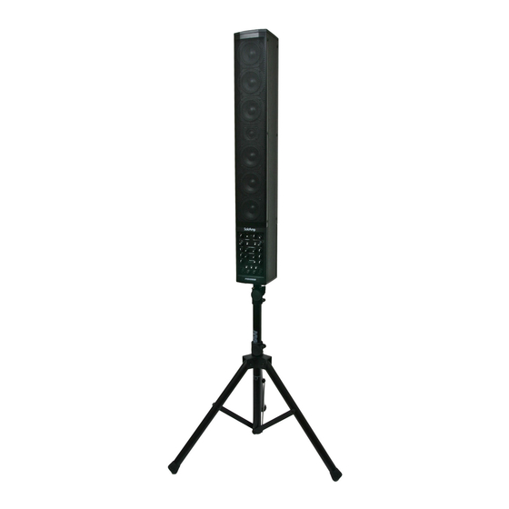
Replace the safety pin. Allow the tube to rest on this pin and tighten the top thumbscrew (Figure 2). Lift the SoloAmp using the handle on the back of the unit while supporting the weight with your other hand. A guide is molded into the underside of the SoloAmp and acts as an aid in positioning the SoloAmp onto the tripod. - Page 5 Plug the provided AC line cord into the back of the amplifier. Locate the Power switch and switch it off, then connect the power cord. Plug the SoloAmp into an electrical outlet with the appropriate AC voltage. Push in the Mute switch and turn on the Power switch.
-
Page 6: Front Panel Controls
XLR outputs. The mute does not affect the Aux Input, Monitor Input, Tuner Out or the effects sends. 2. Master Volume – Set the overall level of the SoloAmp with the Master Volume. Note: Controls 3 through 13 are identical for both channels. - Page 8 Front Panel Controls (cont.) 11. 10dB Pad – If you have a high output pickup and the Clip LED comes on at low Gain settings, push this switch in for a more usable range. 12. XLR Mic Input – You may also connect an outboard preamp with balanced XLR out to this input.
-
Page 10: Rear Panel Controls
23. Tweeter Level – Set the front panel controls fl at and adjust the tweeter level to where it sounds best to you. 24. AC Power The SoloAmp has a universal power supply and can accept voltages from around the world. For amplifiers purchased in the USA, Canada and Mexico, plug in the supplied detachable AC power cable. - Page 11 SoloAmp Model: PRO-AMP-SL1 Input: 100-240V ~50/60Hz Max. Power: 265Watts / 3.15A 37MF Date Code: E323115...
- Page 12 SoloAmp, to “cross-feed” their EQ’d and mixed outputs to each other. This allows each player to turn up the other player’s mix and only hear it also in their SoloAmp. It essentially acts as a monitor, allowing the performer to hear the other player more easily.
- Page 13 SoloAmp Model: PRO-AMP-SL1 Input: 100-240V ~50/60Hz Max. Power: 265Watts / 3.15A 37MF Date Code: E323115...
-
Page 14: About Acoustic Feedback
About Acoustic Feedback There are two features provided to help control acoustic feedback, the Phase switch and the Anti-Feedback notch control. Feedback usually occurs in the lowest octaves of your instrument. The natural resonances which produce an instrument’s tone also react with amplifi ed sound. The louder an instrument is amplifi... - Page 15 Setting Phase and Anti-Feedback The Phase and Anti-feedback controls can be used to restrict the two most dominant feedback notes, allowing greater volume before feedback than otherwise possible. In most cases, the Phase switch is used to control the lower dominant note while the Anti-Feedback notch is used to control the higher.
-
Page 16: Monitor Feature
Monitor Feature The monitor feature on the SoloAmp allows two performers, each with a SoloAmp, to “cross-feed” their EQ’d and mixed outputs to each other. This allows each player to turn up the other player’s mix and hear it through in their own SoloAmp. -
Page 17: Phantom Power Faqs
A: All the following can be used safely with phantom power: 1: All balanced condenser microphones. 2: All balanced dynamic microphones. 3: Many new wireless units. Check with the manufacturer for compatibility. 4: A preamp/D.I. designed for phantom-power operation, such as the Fishman Pro-EQ Platinum. -
Page 18: Block Diagram
Block Diagram... -
Page 19: Technical Specifications
Technical Specifications Channel 1 & 2 D.I. Out Output Impedance 600 Ohm balanced Phantom power tolerant, ground isolated Channel 1 & 2 Effects Sends: Output Impedance 2k Ohm Output Level -10dBV Nominal Channel 1 & 2 Effects Returns: Input Impedance 20k Ohm Input Voltage +3dBV (1.4Vrms max) - Page 20 Fishman and Fishman Transducers are trademarks or tradenames of Fishman Transducers Inc. 513-300-118 Rev H, 9-08...