
Related Manuals for Viper 500 ESP


Summary of Contents for Viper 500 ESP
- Page 1 ® 500 ESP Installation Guide ® © 1999 Directed Electronics, Inc. Vista, CA N439 12-99...
-
Page 2: Table Of Contents
table of contents What Is Included ..... 3 Shock Sensor Harness, 4-Pin Connector ..23 Installation Points to Remember ..4 Internal Programming Jumper . -
Page 3: What Is Included
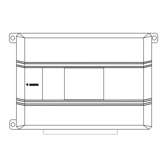
what is included The control module (see diagram) Two 476 Series four-button remote transmitters A plug-in status LED A plug-in Valet ® /Program switch A plug-in Stinger® shock sensor A Revenger ® Soft Chirp ® siren PC Program/Data Port Blue 2-Pin Valet ®... -
Page 4: Installation Points To Remember
installation points to remember This product represents many years of research and development. It is very sophisticated and should be installed by experienced security installers only. Please do not attempt installation of this product without reading this guide. The system has been designed to provide the ultimate in security, coupled with limitless convenience and expansion options. -
Page 5: Deciding On Component Locations
deciding on component locations locations for the siren Some things to remember about mounting the siren: Keep it away from heat sources, such as radiators, exhaust manifolds, turbochargers, and heat shields. Mount it where a thief cannot easily disconnect it, whether the hood is open or shut. Both the siren and its wires should be difficult to find. -
Page 6: Shock Sensor
The higher the control module is in the vehicle, the better the transmitter range will be. If you put the control module under a seat or inside a metal dashboard, range will suffer, and you may wish to add a DEI ®... -
Page 7: Valet/Program Switch
locations for valet/program switch IMPORTANT! When the vehicle is delivered, please show the user where this switch is located and how to disarm the system with it. Ensure that the location you pick for the switch has sufficient clearance to the rear. The switch should be well hidden. -
Page 8: Starter Kill Relay
locations for the starter kill relay If starter kill relay or its connections are immediately visible upon removal of the under-dash panel, they can easily be bypassed. Always make the relay and its connections difficult to discern from the factory wiring! Exposed yellow butt connectors do not look like factory parts, and will not fool anyone! For this reason, routing the starter kill wires away from the steering column is recommended. -
Page 9: Starter Wire
How to find (+)12V ignition with your multimeter: 1. Set to DCV or DC voltage (12V or 20V is fine). 2. Attach the (-) probe of the meter to chassis ground. 3. Probe the wire you suspect of being the ignition wire. The steering column harness or ignition switch harness is an excellent place to find this wire. -
Page 10: Making Your Wiring Connections
Once you have determined the wire color, the easiest place to connect to the wire is often at the kick panel, at the windshield pillar, or in the running board. When an easy location is not available, running a wire to the dome- light itself is often the best solution. -
Page 11: Primary Harness (H1), 12-Pin Connector
primary harness (H1), 12-pin connector ______ ORANGE (-) 500 mA ARMED OUTPUT H1/1 ______ WHITE (+)/(-) SELECTABLE LIGHT FLASH OUTPUT H1/2 ______ WHITE/BLUE (-) 200 mA CHANNEL 3 PROGRAMMABLE OUTPUT H1/3 ______ BLACK/WHITE (-) 200 mA DOMELIGHT SUPERVISION OUTPUT H1/4 ______ GREEN (-) DOOR TRIGGER INPUT, ZONE 3... - Page 12 IMPORTANT! Never interrupt any wire other than the starter wire. H1/2 WHITE light flash output As shipped, this wire should be connected to the (+) parking light wire. If the light flash polarity jumper under the sliding door is moved to the opposite position (see Internal Programming Jumpers section of this guide), this wire supplies a (-) 200 mA output.
- Page 13 H1/3 WHITE/BLUE 200 mA (-) channel 3 output This wire provides a 200 mA (-) output whenever the transmitter button(s) controlling channel three is pressed. This output can be programmed to provide the following types of output (see System Features Learn Routine section of this guide): A validity output will send a signal as long as the transmission is received.
- Page 14 H1/5 GREEN (-) door trigger input Most vehicles use negative door trigger circuits. Connect the green wire to a wire which shows ground when any door is opened. In vehicles with factory delays on the domelight circuit, there is usually a wire that is unaffected by the delay circuitry.
- Page 15 H1/8 BLACK (-) chassis ground connection Connect this wire to bare metal, preferably with a factory bolt rather than your own screw. (Screws tend to either strip or loosen with time.) We recommend grounding all your components, including the siren, to the same point in the vehicle.
-
Page 16: Door Lock Harness (H2), 3-Pin Connector
H1/11 RED (+)12V constant power input Before connecting this wire, remove the supplied fuse. Connect to the battery positive terminal or the constant 12V supply to the ignition switch. NOTE: Always use a fuse within 12 inches of the point you obtain (+)12V. Do not use the 10A fuse in the harness for this purpose. -
Page 17: Door Lock Harness (H2) Wire Connection Guide
door lock harness (H2) wire connection guide type A: (+) 12V pulses from the switch to the factory relays The system can control a Type A system directly, with no additional parts. The switch will have three wires on it, and one will test (+)12V constantly. The others will alternately pulse (+)12V when the switch is pressed to the lock or unlock position. -
Page 18: Negative-Triggered, Relay Driven Systems (Type B)
type B: (-) pulses from the switch to the factory relays This system is common in many Toyota, Nissan, Honda, and Saturn models, as well as Fords with the keyless- entry system (some other Fords also use Type B). The switch will have three wires on it, and one wire will test ground all the time. One wire will pulse (-) when the switch locks the doors, and the other wire will pulse (-) when the switch unlocks the doors. -
Page 19: Reversing Polarity (Type C)
type C: reversing polarity Interfacing with a reversing polarity system requires either two relays or one 451M (not included). It is critical to identify the proper wires and locate the master switch to interface properly. Locate wires that show voltage on lock and unlock. Cut one of the suspect wires and check operation of the locks from both switches. -
Page 20: After-Market Actuators (Type D)
type D: after-market actuators In order for this system to control one or more after-market actuators, a 451M or two relays (optional) are needed. Vehicles without factory power door locks require the installation of one actuator per door. This requires mounting the door lock actuator inside the door. -
Page 21: Electrically Activated Vacuum (Type E)
type E: mercedes-benz and audi (1985 and newer) Door locks are controlled by an electrically activated vacuum pump. Some Mercedes and Audi models use a Type D system. Test by locking doors from the passenger key cylinder. If all the doors lock, the vehicle's door lock system can be controlled with just two relays (optional). -
Page 22: One-Wire System, (Type F)
type F: one-wire system This system usually requires a negative pulse to unlock, and cutting the wire to lock the door. In some vehicles, these are reversed. It is found in late-model Nissan Sentras, some Nissan 240SX, and Nissan 300ZX 1992 and later. It is also found in some Mazda MPV's and some Mitsubishi's. -
Page 23: Programmer Interface
programmer interface, 3-pin black plug The black three pin port is provided for personal computer programming of the unit. When using the DEI Bitwriter (P/N 998T) or optional PC Interface module (P/N 996T) it is possible to configure any and all of the program- mable functions using an IBM-compatible personal computer. -
Page 24: Internal Programming Jumper
internal programming jumper light flash jumper This jumper is used to determine the light flash output. In the (+) position, the on-board relay is enabled and the unit will output (+)12V on the WHITE wire, H1/2. In the (-) position, the on-board relay is disabled. The WHITE wire, H1/2, will supply a 200 mA (-) output suitable for driving factory parking light relays. -
Page 25: Bypassing Sensor Inputs
bypassing sensor inputs There are times when you need to temporarily bypass all sensor inputs to the unit, such as when remote start- ing the vehicle. Anytime an auxiliary channel output is used, all inputs are bypassed for 5 seconds. During the 5 second bypass period, ground can be supplied to the H1/6 Blue wire without triggering the unit. -
Page 26: System Features Learn Routine
system features learn routine The System Features Learn Routine™ dictates how the unit operates. Due to the number of steps, they have been broken up into two menus. It is possible to access and change any of the feature settings using the Valet®/Program switch. -
Page 27: Once A Feature Is Programmed
NOTE: The Valet® pulse count feature (2-5) and the Channel three timed output (2-9) have five possible settings each. Pressing will toggle through all the possible settings. Release the Valet®/Program button. once a feature is programmed Other features can be programmed within the same menu. Another menu can be selected. -
Page 28: System Features Menus
system features menus menu #1 - basic features Items in bold text have been programmed to the two chirps setting at the factory. FEATURE NUMBER ONE-CHIRP SETTING (DEFAULT) TWO-CHIRP SETTING Active arming Passive arming Chirps on Chirps off Ignition-controlled door locks on Ignition-controlled door locks off Active locking only Passive locking... -
Page 29: Feature Descriptions
feature descriptions The features of the system are described below. If the system is being programmed with a DEI® Bitwriter™ or 996T and a personal computer the options available may change. PC programmable options are indicated by the following icon: menu #1 - basic feature descriptions 1-1 ACTIVE/PASSIVE ARMING: When active arming is selected, the system will only arm when the transmitter is used. -
Page 30: Menu #2-Advanced Feature Descriptions
1-8 AUTOMATIC ENGINE DISABLE (AED) ON/OFF: AED is a full-time, passive starter disable that works independently of the security system. When turned on, the orange, ground-when-armed output (H1/1) will go active 30 seconds after the ignition is turned off. The LED will flash at half its normal rate when the ignition is turned off to indicate that AED is active and will interrupt the starter in 30 seconds. - Page 31 2-4 PROGRESSIVE DOOR TRIGGER ON/OFF: The system responds to a door trigger input with a progressive response. When the door is opened with the system armed, the siren will chirp 10 times prior to the full trig- gered sequence. The door trigger is still treated as an instant trigger and closing the door quickly will not prevent a full triggered sequence from occurring.
-
Page 32: Transmitter/Receiver Learn Routine
transmitter /receiver learn routine The system comes with two transmitters that have been taught to the receiver. The receiver can store up to 4 different transmitter codes in memory. Use the following learn routine to add transmitters to the system or to change button assignments if desired. - Page 33 Press the transmitter button: While holding the Valet®/Program switch, press the button from the transmitter that you wish to assign to the selected channel. The unit will chirp indicating successful programming. It is not possible to teach a transmitter button to the system more than once.
-
Page 34: Transmitter Configurations
transmitter configurations The transmitters can be programmed with the standard or single button arm/disarm configurations by using the Auto Learn functions in the Transmitter/Receiver Learn Routine. standard configuration A remote that uses the standard configuration operates similarly to many factory keyless entry remotes. A stan- dard configuration transmitter allows arming, disarming, and Panic Mode activation with separate buttons. -
Page 35: Multi-Level Security Arming
multi-level security arming Multi-Level Security Arming is a feature that allows you to select which of the security system's inputs or sensors will be active and which will be bypassed at the time that the system is armed. (See Table of Zones section in this guide.) Pressing the arm button (only on a Standard Configuration transmitter) again within five seconds of arming the security system will activate the Multi-Level Security Arming feature. -
Page 36: Long-Term Event History
long term event history The system stores the last two full triggers in memory. These are not erasable. Each time the unit sees a full trigger, the older of the two triggers in memory will be replaced by the new trigger. To access long term event history: With the ignition off, press and hold the Valet®/Program switch. -
Page 37: To Disarm Vrs
to disarm VRS To disarm VRS (before siren begins chirping): Turn the ignition to the ON position. Press the unlock button on the transmitter for 1 second. The parking lights will flash twice and the siren will chirp twice to confirm that the VRS® system is disarmed. To disarm VRS (after siren has begun chirping): Turn the ignition to the ON position. -
Page 38: Troubleshooting
troubleshooting Starter kill doesn’t work. Is the correct starter wire being interrupted? If the car starts when the starter kill relay is completely discon- nected, the wrong starter wire has been cut and interrupted. Yellow wire is not connected to true ignition. It is connected to an accessory circuit. Shock sensor doesn’t trigger the alarm.