Raymarine E-Series Installation Manual
E-series networked display
Hide thumbs
Also See for E-Series:
- Reference manual (360 pages) ,
- User reference handbook (260 pages) ,
- Installation instructions manual (112 pages)

Related Manuals for Raymarine E-Series


Summary of Contents for Raymarine E-Series
- Page 1 E-Series Networked Display Installation Manual Document Number: 87043_1 Date: December 2004 www.busse-yachtshop.de | info@busse-yachtshop.de...
-
Page 2: Trademarks And Registered Trademarks
Autohelm, HSB, Raymarine, RayTech, RayTech Navigator, Sail Pilot, SeaTalk and Sportpilot are registered trademarks of Raymarine Limited. Apelco is a registered trademark of Raymarine Holdings Limited (Registered in all major marketing territories). AST, Autoadapt, Auto GST, Autoseastate, Autotrim, Bidata, Marine... -
Page 3: Table Of Contents
Media storage cards ..................10 Navionics Chart cards ................10 CompactFlash cards ................10 2.3 Functionality .......................10 2.4 How is an E-Series integrated? ................11 Single display system ..................12 Networking E-Series Displays ................13 A typical two node system incorporating two displays ........14 An example of a three (or more) node system ..........15... - Page 4 ...for new installations ...............28 ... to replace a Raymarine Pathfinder Display ........29 Chapter 4: Commissioning the system ..............31 4.1 Introduction ......................31 4.2 What input does my E-Series require? ..............31 4.3 Pre-start checks ....................32 Radar ....................32 Fishfinder ...................32 GPS ....................32 4.4 Initial power on procedure ..................33 4.5 How do I test and align the radar? ..............33...
- Page 5 5.2 How can I get Technical Support? ...............42 World wide web ....................42 Help us to help you ..................42 How can I contact Raymarine in the US? ............43 Who do I contact for accessories and parts? ..........43 Who do I contact for product repair and service? ........43 How can I contact Raymarine in Europe? ............44...
- Page 6 Table of Contents www.busse-yachtshop.de | info@busse-yachtshop.de...
-
Page 7: Important Information
Important Information Important Information Safety notices WARNING:Navigation aid This product is intended to be used as an aid to navigation. Its accuracy can be affected by many factors, including equipment failure or defect, environmental conditions and incorrect handling or use. It is the Users responsibility to exercise common prudence and navigational judgement. - Page 8 E-Series Installation Manual CAUTION: Radar Scanners, Cables & Installation Information on radar scanners, cables and their installation contained in this handbook supersedes that contained in the Pathfinder Radar Scanner Handbook, Document No. 81154_6, dated 11th March 2002. CAUTION: Front cover clip-on installation After installing the front cover clip-on, check that all buttons and soft keys have passed through completely and are free to operate correctly.
-
Page 9: Handbook Information
Important Information EMC Conformance All Raymarine equipment and accessories are designed to the best industry standards for use in the recreational marine environment. The design and manufacture of Raymarine equipment and accessories conform to the appropriate Electromagnetic Compatibility (EMC) standards, but correct installation is required to ensure that performance is not compromised. - Page 10 E-Series Installation Manual www.busse-yachtshop.de | info@busse-yachtshop.de...
-
Page 11: Chapter 1: Preparation For Installation
This handbook provides information and instructions to assist in planning and installing your Raymarine E-Series Networked Display, together with information that will be useful when you are connecting the E-Series Display to other equipment. In order to obtain the best results in operation and performance, please read this handbook thoroughly. -
Page 12: Contents Of This Pack
E-Series Installation Manual Contents of this pack The E- Series (E80 or E120) Networked Display pack contains the following items: Pack details Part no. Part name E120 Networked display E02011 E02013 Front cover clip-on R58183 R58194 Sun cover R58184 R58195 Cables (all 1.5m):... -
Page 13: Dimensions
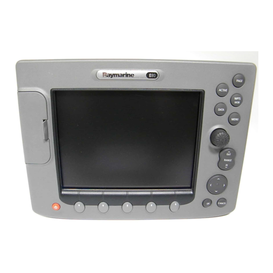
Chapter 1: Preparation for installation Dimensions The dimensions for your E-Series display are: E80 Display Weight 4.18 kg PAGE ACTIVE WPTS DATA MENU RANGE CANCEL 9.5 mm (0.375 in) 283 mm (11.14 in) 123 mm (4.84 in) 315 mm (12.4 in) 154 mm (6.1 in) -
Page 14: Accessories And Spares
However, if you are in need of an item not available from the retailer or you are uncertain what item to choose for your Display, please contact Raymarine direct - See “How can I get Technical Support?” on page 42. -
Page 15: Planning The Installation
This will not damage the equipment, but may cause the loss of some infor- mation and may change the operating mode. • Raymarine specified cables are used. Cutting and rejoining these cables can com- promise EMC performance and must be avoided unless doing so is detailed in the installation manual. -
Page 16: Suppression Ferrites
Raymarine. D6626-1 Connections to other equipment If your Raymarine equipment is to be connected to other equipment using a cable not supplied by Raymarine, a suppression ferrite MUST always be attached to the cable near to the Raymarine unit. -
Page 17: Chapter 2: System Integration
• SeaTalk • National Marine Electronics Association (NMEA)0183. • NMEA 2000. • SeaTalk High Speed. When two or more E-Series Displays are networked, all shared data can be viewed on any display. What is SeaTalk? SeaTalk The SeaTalk protocol enables compatible instruments to be connected to a simple network by way of a single cable carrying power (12 volts, 150 mA) and data in/out, without a central processor. -
Page 18: What Is Seatalk High Speed
E-Series Installation Manual devices to talk to each other, whilst maintaining near transparent NMEA 2000 compatibility. What is SeaTalk High Speed? SeaTalk High Speed is designed to provide a ‘plug and play’, ethernet based marine network. It supports up to 8 nodes e.g. 7 displays and a DSM300, which can be connected to a compatible device, display, DSM etc. -
Page 19: Compatibility
If your radar scanner requires upgrading, please contact your local Raymarine dealer for full information. Digital Sounder Module Important: In order for your Digital Sounder Module (DSM) to be compatible with your E-Series display, you will need a DSM300 (Part no. E63049). www.busse-yachtshop.de | info@busse-yachtshop.de... -
Page 20: Media Storage Cards
Outside of North America, contact your local dealer or call Navionics SpA on tel: (+39) 0584 961696 or fax: (+39) 0584 961309. CompactFlash cards It is possible to archive or transfer information to and from your E-Series display and other compatible instruments using CompactFlash cards. To achieve the best results it ®... -
Page 21: How Is An E-Series Integrated
You can integrate: • A single E-Series display. • Connect two E-Series displays or an E-Series display and a DSM 300 via a crossover coupler. • Connect two or more E-Series displays and a DSM300 if required via a SeaTalk High Speed switch to form a network. -
Page 22: Single Display System
E-Series Installation Manual Single display system This simple system incorporates a single E-Series display with a DSM 300 and radar. E-series display Open array scanner Radome scanner Radar Crossover coupler DSM 300 Video player Onboard camera DVD player SeaTalk system... -
Page 23: Networking E-Series Displays
Chapter 2: System Integration Networking E-Series Displays You can connect two or more E-Series Displays to create a network. This will enable you to input, view and maintain data across all your Displays and enable multiple SeaTalk instruments to communicate with one another. -
Page 24: A Typical Two Node System Incorporating Two Displays
E-Series Installation Manual A typical two node system incorporating two displays Open array scanner Supplied Not supplied/ accessory Radome scanner SeaTalk high speed SeaTalk high speed E-series display E-series display Crossover coupler Video player Video player Onboard camera Onboard camera... -
Page 25: An Example Of A Three (Or More) Node System
Chapter 2: System Integration An example of a three (or more) node system www.busse-yachtshop.de | info@busse-yachtshop.de... - Page 26 E-Series Installation Manual www.busse-yachtshop.de | info@busse-yachtshop.de...
-
Page 27: Chapter 3: Installation
Scanner Handbook, Document No. 81154_6, dated 11th March 2002. Introduction This chapter provides instructions for installing your E-Series Display. You may find that your system does not use all the protocols or contain all of the instrumentation that is described. - Page 28 E-Series Installation Manual page 20 i. Locate the front cover clip-on over the front of the display - see ii. Check that the buttons have passed through the cover and are free to operate. It is suggested that you use your thumb or forefinger in a circular motion to do this.
-
Page 29: Flush Mounting The Display
10. Fit the front cover clip-on onto the display - see Washer, Flush mounted display Spring M4 (x4) washer, M4 (x4) Bolt, M4 x 40 hexhead (x4) Nut, M4 (x4) Front cover clip-on E-series display unit Panel seal D7212_1 www.busse-yachtshop.de | info@busse-yachtshop.de... -
Page 30: How Is The Front Cover Clip-On Attached To The Display
1. Carefully lift one edge of the screen protection film, so that it is accessible for removing when unit installation is complete. 2. Place the front cover clip-on onto the E-Series Display, ensuring that the locking lugs (located at the bottom edge of the covers) are latched into position. -
Page 31: How Do I Remove The Front Cover Clip-On
Chapter 3: Installation How do I remove the front cover clip-on? D7214_1 To remove the clip- on front cover: 1. To prevent damaging your dash or placing undue strain on the trunnion bracket, remove the unit from its mounting before proceeding. If you have flush mounted your Display and cannot readily gain access to the rear of the unit, protect the dash and proceed with caution. -
Page 32: Cables
E-Series Installation Manual 3.2 Cables This section details how to instal and connect all the relevant cables to your E-Series Display. Siting and securing cables When installing system cables, please note the following: • All cables should be adequately secured, protected from physical damage and exposure to heat. -
Page 33: How Are The Cables Connected To The Display
Chapter 3: Installation How are the cables connected to the display? The cable connections are located on the back of the display unit. All cables can be connected prior to mounting the unit on the trunnion bracket. CAUTION: Do not remove the SeaTalk High Speed blanking plug from the rear of the display until such time as you are ready to connect the cable. -
Page 34: How Do I Use The Cable Splicers
4. Ensure that the cables are secured in a suitable position to prevent the join being placed under strain. Power cable The E-Series Display is intended for use on boats’ DC power systems rated at 12v or 24v. The power connection should be made at either the output of the battery isolating switch, or at a DC power distribution panel. -
Page 35: Extension Cable
Chapter 3: Installation Extension cable If an extension power cable is required, please note the following: • The wire gauge used may be affected by the scanner type. • To minimize voltage drops, use large gauge cable. • Use the supplied power cable to connect to the display unit. Then use a suitable connector block to connect the free end to the extension cable, taking particular care to ensure the correct polarity. -
Page 36: Nmea 0183 Cable
Your E-Series display will support on-board cameras, DVD or video players etc. using composite or S-Video source type. If you have an E-Series network, you will need to connect the input source to the individual display on which it is to be viewed as video images cannot be seen across the SeaTalk High Speed network. -
Page 37: Composite Source Type
Chapter 3: Installation Composite source type Use the supplied cable to connect up to 4 composite source inputs to your E-Series Display. The color of each connector defines the video number to which it configures within the Video Setup Menu: •... -
Page 38: Radar Cable (Not Supplied)
E-Series Installation Manual Radar cable (not supplied) Having ensured that the radar scanner you are using is compatible with the E-Series Display (see “Compatibility” on page 9), the cable should be connected as follows: Connecting to a Radome If you are using a radome this can be powered through the display. Just run your cable and connect it to the radome and the display. -
Page 39: To Replace A Raymarine Pathfinder Display
(using a convertor if necessary) and Boats DC from a common supply source e.g. the same Power Supply battery or power breaker. D7329-1 ... to replace a Raymarine Pathfinder Display Part No Description E55069 2.5m Pedestal adaptor cable Pedestal adaptor cable... - Page 40 E-Series Installation Manual Open Array E-Series Display PAGE ACTIVE WPTS DATA MENU Pedestal adaptor cable (2.5 metres) RANGE CANCEL Power to open array Power to display Note: The power supply for both the display and the open array must be of the same...
-
Page 41: Chapter 4: Commissioning The System
• Chart application checks. • Fishfinder checks. • SeaTalk High Speed checks. • Video in/out. 4.2 What input does my E-Series require? The table below details the data required by each application of your E-Series: Application Multi-media card Datum Compass, autopilot or... -
Page 42: Pre-Start Checks
E-Series Installation Manual 4.3 Pre-start checks Before you perform any functional tests, please carry out the following pre-start checks: Radar • Check that the scanner has been installed in accordance with the instructions con- tained in the relevant handbook. All securing bolts should be fully tightened and any mechanical locking arrangements, as specified, are in place. -
Page 43: Initial Power On Procedure
• The keys light up and after a few seconds a navigation warning is displayed. • If you have networked two or more E-Series displays, you will also hear an alarm and be asked to select the repeater displays. Press SET AS REPEATER on the appropriate Display(s). -
Page 44: Radar Transmission Check
E-Series Installation Manual 1. Press OK to select the highlighted page set. 2. Press PAGE. The currently selected page set is represented on the soft keys. 3. Press the corresponding soft key to display a full window radar application. 4. The scanner warm-up countdown commences. This will take approximately 70 sec- onds. -
Page 45: Bearing Alignment
Chapter 4: Commissioning the system Bearing alignment Adjusting the bearing alignment ensures that targets appear at the correct bearing relative to your boat’s bow. You need to select a visible target of known bearing that is displayed on the radar, and then adjust the radar set up as necessary until the correct bearing reading is obtained. -
Page 46: How Do I Check The Gps
E-Series Installation Manual 3. With RADAR SET UP highlighted, use the trackpad (right) to display the RADAR SET UP menu. 4. Use the trackpad (up/down) to highlight and then the trackpad (right) to select BEARING ALIGNMENT. The menu is removed from the screen and the Bearing Alignment soft key is displayed. -
Page 47: How Do I Check The Heading Data
The option to select differential or satellite differential fix is dependent upon the capabilities of the attached GPS. If your boat is equipped with a Raymarine GPS, the Differential GPS can be switched on or off using the appropriate soft key. -
Page 48: How Do I Test The Fishfinder Application
E-Series Installation Manual 1. Without a chart card installed, press PAGE. 2. Select a full window chart application by pressing the associated key. 3. Zoom out with the RANGE button until the world map is visible. 4. To ensure that the display is responding to position data: i. -
Page 49: How Do I Test The Video
From third party devices on NMEA 0183 Check that appropriate NMEA sentences are being sent from the third party device and on the E-Series Display. Open the digital instrument application and ensure all relevant data is displayed. www.busse-yachtshop.de | info@busse-yachtshop.de... - Page 50 E-Series Installation Manual www.busse-yachtshop.de | info@busse-yachtshop.de...
-
Page 51: Chapter 5: Troubleshooting
Chapter 5: Troubleshooting Chapter 5: Troubleshooting Introduction This chapter provides information on troubleshooting your Raymarine E-Series Display at installation, and how to get assistance from Raymarine. 5.1 How can I troubleshoot my Display? All Raymarine products are, prior to packing and shipping, subjected to comprehensive test and quality assurance programs. -
Page 52: How Can I Get Technical Support
For fastest support - 24 hours a day, seven days a week; go to the Frequently Asked Questions section. Most questions are answered here. The website will also give you servicing information, e-mail access to the Raymarine Technical Support Department and details of the locations of Raymarine agents, worldwide. -
Page 53: How Can I Contact Raymarine In The Us
Chapter 5: Troubleshooting How can I contact Raymarine in the US? You can contact Raymarine in the US either using the Raymarine world wide web as detailed above or by calling one of the telephone numbers below. Who do I contact for accessories and parts? You can obtain many Raymarine accessories and parts directly from your authorized Raymarine dealer. -
Page 54: How Can I Contact Raymarine In Europe
If you wish to enquire about the repair status of your unit, contact the Repair Center at: 1-800-539-5539 How can I contact Raymarine in Europe? You can obtain Technical Support, service and accessories from your authorized Raymarine dealer, or by contacting:...