Table of Contents
Advertisement
Quick Links
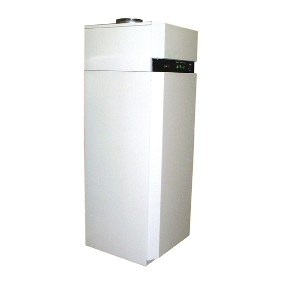
AWP 30 HLW
Warmwasser-
Wärmepumpe für
Innenaufstellung
Bestell-Nr. / Order no. / N
Hot Water Heat
Pump for Indoor
Installation
o
de commande : 451902.66.45
Montage- und
Gebrauchsanweisung
Installation and
Operating Instructions
Instructions d'installation
et d'utilisation
Pompe à chaleur
de production d'eau
chaude à installation
intérieure
FD 8803
Advertisement
Chapters
Table of Contents

Related Manuals for Dimplex AWP 30 HLW


Summary of Contents for Dimplex AWP 30 HLW
- Page 1 AWP 30 HLW Montage- und Gebrauchsanweisung Installation and Operating Instructions Instructions d’installation et d’utilisation Warmwasser- Hot Water Heat Pompe à chaleur Wärmepumpe für Pump for Indoor de production d’eau Innenaufstellung Installation chaude à installation intérieure Bestell-Nr. / Order no. / N de commande : 451902.66.45...
-
Page 2: Table Of Contents
8.1 Water Circuit / Condensate Outflow ....................... E-8 8.2 Air Cycle ..............................E-8 8.3 Corrosion Protection Anode........................E-8 Faults / Trouble-Shooting (for Users)..................E-9 10 Shut-Down .............................E-9 11 Environmental Requirements ......................E-9 12 Technical Data ..........................E-10 Anhang / Appendix / Annexes ......................A-I www.dimplex.de... -
Page 3: Please Read Immediately
Please Read Description Immediately 2.1 General Information 1.1 Important Information The hot-water heat pump is a ready-to-use heating device and mainly consists of hot water cylinders, the components for the re- frigerant, air and water circuits, as well as all of the control, regu- ATTENTION! lation and monitoring devices required for automatic operation. -
Page 4: Refrigerant Circuit (Heat Pump Operating Principle
Circulation is enabled according to use (time or requirement control). Condensate outflow See Point 7.2 "Connecting the Condensed Water Pipe" 1) Alternative condensate hose routing Nominal width of air duct connection DN 160 ⇒ outer diameter –2 www.dimplex.de... -
Page 5: Regulation And Operation
Regulation and Operation 3.1 Hot-water heat pump Operator Panel 3.2 Hot-Water Temperature 3.3 "Heat Pump" Switch Controller (Rotary Controller) The heat pump is ready for operation when the heat pump switch is in the "On" position. If the hot-water temperature in the cylinder The rotary button is used to set the desired hot-water tempera- drops below the set value, the heat pump will be activated until ture. -
Page 6: Heat Exchanger" Switch
An external temperature sensor can be in- serted here. There is a cable feedthrough at the rear of the unit. ATTENTION! The (painted) steel coverings, particularly the upper cover plates, are not designed to withstand large forces! ATTENTION! High centre of mass, low overturning moment! www.dimplex.de... -
Page 7: Set-Up
Set-Up 5.2 Set-Up Remove the three M12 transport restraint screws fixing the unit to the pallet. 5.1 Installation Location Remove pallet and install the three M12 supporting feet (in plastic bag attached to the cylinder barrel nipple). Installation location criteria: Position the hot-water heat pump and align vertically by ad- The unit must be installed in a frost-free space (preferably justing the device feet! Then tighten the counternuts on the... -
Page 8: Electrical Connection
X5 (6 + 7) Connection for external heating element control (optional) X5 (8 + 9) External release contact Heat pump operation is blocked if the factory-mounted copper bridge between pole terminals 8 and 9 is removed (see Section 3.5). www.dimplex.de... -
Page 9: Start-Up
Start-Up 8.1 Water Circuit / Condensate Outflow 7.1 Hot Water System The water circuit check is limited to filters that may have been in- stalled on-site, and possible leakage. Dirty water filters should be ATTENTION! cleaned and replaced if necessary. The seal valve in the con- Only operate hot-water heat pump when filled with water! densed water hose should occasionally be checked for contami- nation, and replaced if necessary. -
Page 10: Faults / Trouble-Shooting (For Users
- clean it, if necessary; the valve can be easily re- moved and replaced ventilation is extremely reduced (bent duct / clogged air filter) If the above questions cannot help you eliminate these faults, please contact your technician or customer services. www.dimplex.de... -
Page 11: Technical Data
12 Technical Data Type and order code AWP 30HLW Design with additional internal heat exchanger Casing Painted sheet steel Colour White, similar to RAL 9003 Nominal cylinder volume Cylinder material Enamelled steel according to DIN 4753 Nominal cylinder pressure Model Dimensions W x H x D (overall) 660 x 700 x 1700 Weight... -
Page 12: Anhang / Appendix / Annexes
Diagram (Example: Thermal Solar Install.) / Schéma d’intégration échangeur thermi. (install. solaire therm. par. ex.)..............................A-IV Stromlaufplan / Circuit Diagram / Schéma électrique............... A-V 2.1 Darstellung / Schematic View / Représentation..................A-V 2.2 Legende / Legend / Légende.........................A-VI Konformitätserklärung / Declaration of Conformity / Déclaration de conformité ....A-VII www.dimplex.de... -
Page 13: Hydraulische Prinzipschemen / Hydraulic Plumbing Diagram / Schéma Hydraulique
1 Hydraulische Prinzipschemen / Hydraulic Plumbing Diagram / Schéma hydraulique 1.1 Kältemittelkreislauf / Refrigerant Circuit / Circuit réfrigérant 1.2 Legende / Legend / Légende Verdichter Compressor Compresseur Pressostat HD High-pressure switch Pressostat HP Verflüssiger Liquifier Condenseur Warmwasserspeicher Hot water cylinder Ballon d’eau chaude Wärmetauscher (nicht alle Typen) Heat exchanger (not all types) -
Page 14: Hydraulisches Einbindungsschema / Hydraulic Block Diagram / Schéma D'intégration Hydraulique
Return flow inhibitor Clapet anti-reflux Manometeranschlussstutzen Pressure gauge connecting stubs Tubulures de raccordement manomètre Entleerungsventil Drain valve Vanne de vidange Membran-Sicherheitsventil Diaphragm safety valve Soupape de sécurité à membrane Zirkulationspumpe Circulation pump Pompe de circulation Abfluss Outlet Ecoulement www.dimplex.de A-III... -
Page 15: Einbindungsschema Wärmetauscher (Bsp. Thermische Solaranlage) / Heat Exchanger Integration Diagram (Example: Thermal Solar Install.) / Schéma D'intégration Échangeur Thermi
1.5 Einbindungsschema Wärmetauscher (Bsp. thermische Solaranlage) / Heat Exchanger Integration Diagram (Example: Thermal Solar Install.) / Schéma d’intégration échangeur thermi. (install. solaire therm. par. ex.) A-IV... -
Page 16: Stromlaufplan / Circuit Diagram / Schéma Électrique
2 Stromlaufplan / Circuit Diagram / Schéma électrique 2.1 Darstellung / Schematic View / Représentation www.dimplex.de... -
Page 17: Legende / Legend / Légende
2.2 Legende / Legend / Légende Brücke Sperre extern – Brücke muss bei Verwen- External bridge block - bridge must be removed if pont de câble externe - lorsqu'un blocage est dung der Sperre entfernt werden block is used (contact open = heat pump blocked) requis, retirer le pont (contact ouvert = PAC blo- (Kontakt offen = Wärmepumpe gesperrt) quée). -
Page 18: Konformitätserklärung / Declaration Of Conformity / Déclaration De Conformité
3 Konformitätserklärung / Declaration of Conformity / Déclaration de conformité www.dimplex.de A-VII... - Page 19 Glen Dimplex Deutschland GmbH Irrtümer und Änderungen vorbehalten. Geschäftsbereich Dimplex Subject to alterations and errors. Am Goldenen Feld 18 Sous réserve d’erreurs et modifications. D-95326 Kulmbach +49 (0) 9221 709 565 www.dimplex.de...