
Related Manuals for Dimplex AWP 300 LW


Summary of Contents for Dimplex AWP 300 LW
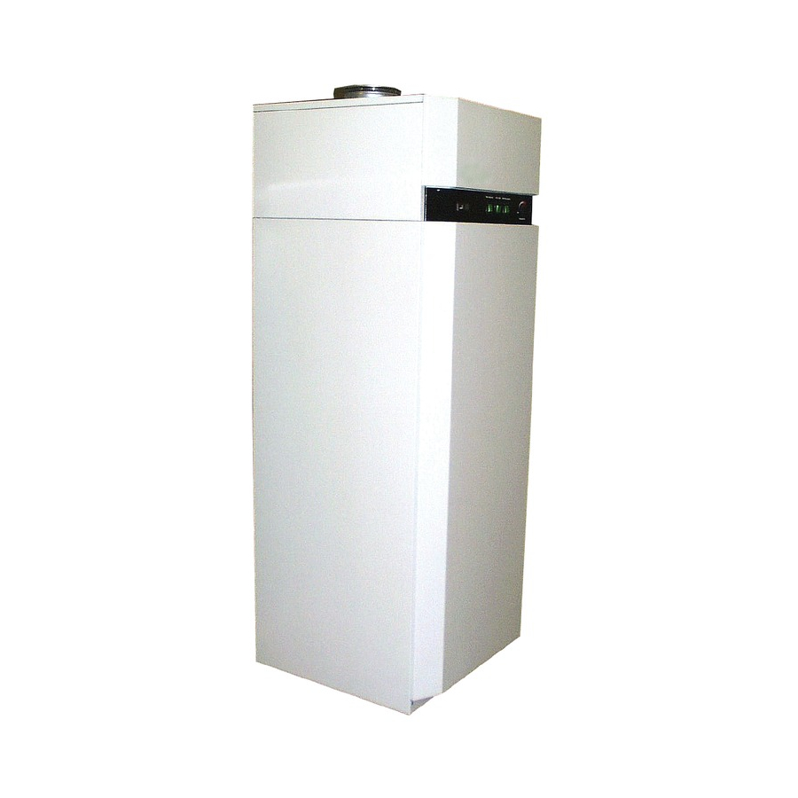
- Page 1 Installation and Operating Manual Heat Pump Water Heater with Sheet-Metal Cabinet, Airduct Connection and Supplementary Heat Exchanger AWP 300 LW 451901.67.19 FD8405...
-
Page 2: Table Of Contents
TABLE OF CONTENTS .......................... Page Regulations / Safety Notices ..................... 3 Description..........................3 Refrigeration Cycle........................4 Water Circuit..........................4 Safety Devices ..........................5 Controlling and Operating Concept..................5 Operating Panel of HPWH ......................5 Hot Water Temperature Controller ....................6 'Heat Pump' Switch ........................ -
Page 3: Regulations / Safety Notices
Regulations / Safety Notices This installation and operating manual must be read before the unit is started up! ¾ ¾ ¾ ¾ # # # # The heat pump water heater (HPWH) is designed exclusively for the heating of domestic or potable wa- ter within the specified operating temperature limits! ¾... -
Page 4: Refrigeration Cycle
Refrigeration Cycle The refrigeration cycle is a closed system in which the refrigerant R134a circulates as an energy carrier. In a finned heat exchanger, heat is extracted from the drawn in air at a low evaporation temperature and trans- ferred to the refrigerant. The vaporous refrigerant is drawn in by a compressor and then compressed to a higher pressure/temperature level;... -
Page 5: Safety Devices
Safety Devices The HPWH is equipped with the following safety features: 2.3.1 High-Pressure Pressostat (HP) The high-pressure pressostat protects the heat pump from excessive operating pressures in the refrigeration cycle. In the case of a malfunction, the pressostat switches off the heat pump. The heat pump is restarted automatically as soon as the pressure in the refrigeration cycle has dropped to an acceptable level. -
Page 6: Hot Water Temperature Controller
Hot Water Temperature Controller The desired hot water temperature can be set using the rotary dial. If the storage tank temperature is lower than the preset hot water temperature setpoint value, the heat pump is activated (provided the 'Heat pump' switch is set to On). -
Page 7: Heat Exchanger' Switch
'Heat Exchanger' Switch The heat exchanger mode is used whenever hot water preparation is to take place by means of a supple- mentary heat source (e.g. in winter by means of a boiler). The standard relay contact, for example, can be used –... -
Page 8: Installation
Installation Installation Site CAUTION! The following applies to the selection of the installation site: ¾ The HPWH must be sited in a freeze-proof room (preferably within the building thermal envelope). The room air temperature and/or the air taken in by the HPWH should be within a temperature range of 8 °C to 35 °C (required for heat pump operation). -
Page 9: Mounting
Mounting Connection of Water Piping The nominal pipe widths of the field-installed sanitary installations must be selected on the basis of the avail- able water pressure and the expected pressure drop within the piping system. The water-side installation has to be executed in compliance with DIN 1988 (see appendix – in the case of excessive water pipe pressure, a pressure relief valve is to be provided, among other things!) The water pipes may be of the rigid or flexible type. -
Page 10: Opening The Cabinet
6.3.1 Opening the Cabinet For feeding in an external cable or inserting a sensor, the "upper side panel" (2) and the "upper front panel" (1) must be removed; to approx. 6 m m this end, the "top cover" (3) need to be loos- ened as well. -
Page 11: Commissioning Of Hot Water System
7.1.2 Commissioning of Hot Water System • Fill hot water circuit via the external connection. • Vent the hot water circuit (open hot water taps at the topmost points of use until no more air escapes). • Perform a leak test of the entire hot water circuit. •... -
Page 12: Sacrificial Anode
Sacrificial Anode The sacrificial anode rod installed in the hot water tank for corrosion protection purposes must be checked electrically on a regular basis - at least every two years - after commissioning and be replaced, if neces- sary. The electrical check is to be conducted by means of a suitable ammeter without draining the water in the tank. -
Page 13: Decommissioning
Decommissioning Activities to be performed: • Disconnect HPWH from the power source. • Completely shut off water circuit (hot water, cold water and circulation line) and drain the hot water stor- age tank. Environmental Requirements Environment-relevant requirements regarding the recovery, reuse and disposal of service fuels and compo- nents in accordance with DIN EN 378 must be adhered to when repairing or decommissioning the HPWH. -
Page 14: Hydraulic Plumbing Diagram
12.2.1 Hydraulic Plumbing Diagram hot water circulation (if required) heating water supply heating water return cold water connection as per DIN 1988 Shut-off valve Non-return valve Diaphragm safety valve Pressure reducing valve 5 Manometer connection Circulating pump (to be mounted above tank edge) Test valve Drain valve Drain... -
Page 15: Circuit Diagram
Heat pump W ärm e pum pe Potential-free contact for P o t.-freie r K on takt Electric heating element E le ktro - H eizstab immersion heater control Compressor Verdich ter Ven tila tor für H eizstaba nst. 230V AC min. 8A 23 0V A C m in . -
Page 16: Technical Data
12.4 Technical Data Exhaust air heat pump water heater AWP 300LW with additional internal heat ex- Type changer Nominal storage tank capacity Storage tank material enamelled steel as per 4753 Nominal tank pressure (bar) Dimensions WxDxH ( (cm) 65 x 70 x 166 overall) Weight (kg) - Page 18 Page 18 of...
- Page 19 Page 19 of...
- Page 20 KKW Kulmbacher Klimageräte-Werk GmbH Subject to technical modifications Division Dimplex Fax (0 92 21) 709-589 Am Goldenen Feld 18 www.dimplex.de D-95326 Kulmbach Page 20 of...