Table of Contents
Advertisement
Quick Links
Advertisement
Table of Contents

Related Manuals for Metrologic IS3480 QuantumE


Summary of Contents for Metrologic IS3480 QuantumE
- Page 2 Copyright © 2006 by Metrologic Instruments, Inc. All rights reserved. No part of this work may be reproduced, transmitted, or stored in any form or by any means without prior written consent, except by reviewer, who may quote brief passages in a review, or provided for in the Copyright Act of 1976.
-
Page 3: Table Of Contents
ABLE OF ONTENTS Introduction Product Overview ..................... 1 Scanner and Accessories................. 2 Scanner Components..................4 Cable Removal....................4 Caution and Serial Number Labels..............5 Mounting Specifications ................... 5 Maintenance..................... 5 Installation RS232, RS232 TTL, Light Pen or Laser Emulation .......... 6 IBM 46xx or OCIA .................... - Page 4 ABLE OF ONTENTS IR Activation Range..................25 Troubleshooting Guide ..................26 Design Specifications ..................30 Applications and Protocols ................. 32 Default Settings - Communication Parameters........... 33 Upgrading the Flash ROM Firmware ..............38 Scanner and Cable Terminations ............... 39 Regulatory Compliance Safety ......................
-
Page 5: Introduction Product Overview
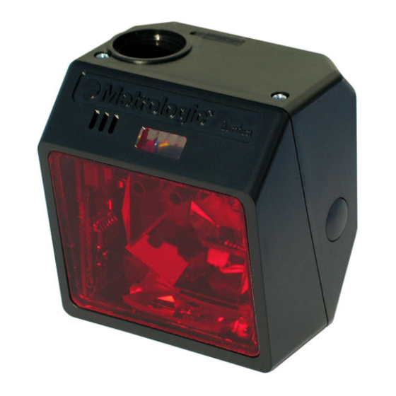
NTRODUCTION ® QuantumE is a miniature, omni-directional scanning engine with optional single- line scanning capability. The self-contained device is fully enclosed eliminating the need for an external window or custom enclosure. It is designed for use in OEM equipment such as price lookup systems and kiosks. Its slim design makes it ideal for integration and use with flat-screens. -
Page 6: Scanner And Accessories
MVC cable series and the host connections available. MVC** Metrologic Voltage Converter Cable ±12VDC to +5.2VDC Other items may be ordered for the specific protocol being used. To order additional items, contact the dealer, distributor or call Metrologic’s customer service department at 1-800-436-3876... - Page 7 203 mm (8") straight cord, short strain relief EPLACEMENT ARTS Part No. Description 36-01822x-3 Rubber Utility Seal Other items may be ordered for the specific protocol being used. To order additional items, contact the dealer, distributor or call Metrologic’s customer service department at 1-800-436-3876.
-
Page 8: Scanner Components
NTRODUCTION Scanner Components Figure 1a. Scanner Components ESCRIPTION Utility Connector Located Under Rubber Seal The rubber seal protecting the utility connector should only be removed if the utility connector is to be used. 10-Pin RJ45, Female Socket Blue, White and Yellow LED Indicators Red Output Window (Laser Aperture) Pin Hole for Cable Release Speaker... -
Page 9: Caution And Serial Number Labels
NTRODUCTION Caution and Serial Number Labels Figure 2. Caution To maintain compliance with applicable standards, all circuits connected to the scanner must meet the requirements for SELV (Safety Extra Low Voltage) according to EN/IEC 60950-1. To maintain compliance with standard CSA C22.2 No. 60950-1/UL 60950-1 and norm EN/IEC 60950-1, the power source should meet applicable performance requirements for a limited power source. -
Page 10: Installation
NSTALLATION RS232, RS232 TTL, Light Pen or Laser Emulation Turn off the host device. Plug the male 10-pin RJ45 end of the PowerLink cable into the 10-pin socket on the IS3480. Connect the 9-pin female end of the PowerLink cable to the host device. Note: Skip to step 6 if receiving power from the host device. -
Page 11: Ibm 46Xx Or Ocia
NSTALLATION IBM 46xx or OCIA Turn off the host device. Plug the male 10-pin RJ45 end of the MVC cable into the 10-pin socket on the IS3480. Connect the other end of the MVC cable to the host device. Turn on the host device. Figure 5. -
Page 12: Keyboard Wedge
Not all computers supply the same current through the keyboard port. For this reason, Metrologic recommends using an external power supply. For additional information, contact a Metrologic customer service representative. -
Page 13: Stand-Alone Keyboard
Not all computers supply the same current through the keyboard port. For this reason, Metrologic recommends using an external power supply. For additional information contact a Metrologic customer service representative. -
Page 14: Low Speed Usb (Integrated)
NSTALLATION Low Speed USB (Integrated) Turn off the host device. Plug the male 10-pin RJ45 end of the USB PowerLink cable into the 10-pin socket on the IS3480. Plug the other end of the USB interface cable into the host device’s USB port. -
Page 15: Notes For Laser Emulation
NSTALLATION Notes for Laser Emulation IS3480-104 Only The IS3480-104 leaves the factory with the Laser Emulation Mode enabled. If the Recall Defaults bar code is scanned while reconfiguring the scanner the laser emulation mode will no longer be enabled. Scan the following barcode to re-enable the laser emulation interface. This feature is only supported for IS3480-104 models. -
Page 16: Scanner Operation
CANNER PERATION Configurable Primary and Secondary Scan Pattern Modes There are two configurable scan pattern modes available with the IS3480. • The primary scan pattern mode is the default scan pattern active when the scanner starts. • The secondary scan pattern mode is activated by pressing the button located on the side of the scanner. - Page 17 CANNER PERATION Configurable Button Functions ECONDARY ATTERN UTTON LICK ODE WITH NABLED For illustration purposes the unit’s primary scan pattern has been set to all scan lines (omnidirectional reading) and the secondary pattern has been set to single-line (menu reading) with a 10 second button click timeout configured.
- Page 18 CANNER PERATION Configurable Button Functions ECONDARY ATTERN UTTON LICK ODE WITH ISABLED For illustration purposes the unit’s primary scan pattern has been set to all scan lines (omnidirectional reading) and the secondary pattern has been set to single-line (menu reading) with a 10 second button click timeout configured.
- Page 19 CANNER PERATION Configurable Button Functions ECONDARY ATTERN UTTON ODE WITH NABLED For illustration purposes the unit’s primary scan pattern has been set to all scan lines (omnidirectional reading) and the secondary pattern has been set to single-line (menu reading) with a 10 second button click timeout configured.
- Page 20 CANNER PERATION Configurable Button Functions ECONDARY ATTERN UTTON ODE WITH ISABLED For illustration purposes the unit’s primary scan pattern has been set to all scan lines (omnidirectional reading) and the secondary pattern has been set to single-line (menu reading) with a 10 second button click timeout configured.
-
Page 21: Sweet Spot Mode
CANNER PERATION Sweet Spot Mode The sweet spot mode is used to determine where the maximum read rate area or “sweet spot” is located for a specific bar code type. When activated this mode provides visual and audible feedback indicating how the scanner is scanning. Number of Illuminated LEDs Beeper Pitch % of Maximum Read Rate... -
Page 22: Audible
CANNER PERATION Audible Indicators When the IS3480 is in operation, it can provide audible feedback. These sounds indicate the status of the scanner. Eight settings are available for the tone of the beep (normal, 6 alternate tones and no tone). For instruction on how to change the tone of the beeper, refer to the MetroSelect Configuration Guide (00-02407). -
Page 23: Visual
CANNER PERATION Visual Indicators There are four LEDs located on the top of the IS3480. When the scanner is on, the flashing or constant illumination of the LEDs indicates the status of the current scan and the scanner. No LEDs The LEDs will not be illuminated if the scanner is not receiving power from the host or transformer. -
Page 24: Failure
CANNER PERATION Failure Mode Indicators Flashing Blue and One Razzberry Tone This indicates that the scanner has experienced a laser subsystem failure. Return the unit to an authorized service center for repair. Flashing Blue and White and Two Razzberry Tones This indicates that the scanner has experienced a motor failure. -
Page 25: Depth Of Field Specifications
CANNER PERATION Depth of Field Specifications* Normal Scan Zone Specifications are based on a 0.33 mm (13 mil) bar code. Figure 9. Normal Depth of Field * All specifications are subject to change without notice. -
Page 26: Reduced Scan Zone
CANNER PERATION Depth of Field Specifications* Reduced Scan Zone Specifications are based on a 0.33 mm (13 mil) bar code. Figure 10. Reduced Depth of Field * All specifications are subject to change without notice. -
Page 27: Depth Of Field By Bar Code Element Width
CANNER PERATION Depth of Field by Bar Code Element Width* Normal Scan Zone INIMUM LEMENT IDTH mils Figure 11. Normal Scan Zone by Bar Code Element Width * All specifications are subject to change without notice. -
Page 28: Reduced Scan Zone
CANNER PERATION Depth of Field by Bar Code Element Width* Reduced Scan Zone INIMUM LEMENT IDTH mils Figure 12. Reduced Scan Zone by Bar Code Element Width * All specifications are subject to change without notice. -
Page 29: Ir Activation Range
CANNER PERATION IR Activation Range* † QuantumE’s default power save mode is Laser OFF. This power save mode turns the laser off after a configured period of non-use. Any movement detected by the IR in the activation area will cause the scanner to exit power save mode. The laser will automatically turn back on preparing the scanner for bar code recognition, decoding and transmission. -
Page 30: Troubleshooting Guide
ROUBLESHOOTING UIDE The following guide is for reference purposes only. Contact a Metrologic representative at 1-800-ID-METRO or 1-800-436-3876 to preserve the limited warranty terms on page 46. Symptoms Possible Cause(s) Solution All Interfaces Check the transformer, outlet The unit has no No power is being and power strip. - Page 31 ROUBLESHOOTING UIDE Symptoms Possible Cause(s) Solution All Interfaces The unit scans If the scanner is setup to support The scanner is a bar code, but ACK/NAK, RTS/CTS, configured to support locks up after XON/XOFF or D/E, verify that some form of host the first scan the host cable and host are handshaking but is not...
- Page 32 ROUBLESHOOTING UIDE Symptoms Possible Cause(s) Solution All Interfaces During power There is a non-volatile Contact a Metrologic service up the unit RAM failure. representative. beeps 3 times. During power up the unit There is a RAM or Contact a Metrologic service razzes ROM failure.
- Page 33 ROUBLESHOOTING UIDE Symptoms Possible Cause(s) Solution RS232 Only The host is The scanner and host Check that the scanner and the receiving data may not be configured host are configured for the same but the data does for the same interface. interface.
-
Page 34: Design Specifications
ESIGN PECIFICATIONS IS3480 Operational Light Source: Visible Laser Diode (VLD) @ 650 nm Laser Power: 1.1 mW Normal Depth of Field: 25 mm - 280 mm (1”- 11”) 0.33 mm (13 mil) bar code Reduced Depth of Field: 25 mm - 150 mm (1”- 6”) Omni Scan Scan Speed: 1650 scan lines per second... - Page 35 ESIGN PECIFICATIONS IS3480 Electrical Voltage Supply: 5VDC ± 0.25V Operating Power: 1.375 W Standby Power: 1.0 W Operating Current: 275 mA typical at 5VDC Standby Current: 200 mA typical at 5VDC DC Transformers: Class II; 5.2VDC @ 1A For regulatory compliance information, see pages 43 – 45. Environmental Operating Temperature: -20°C to 40°C (-4°F to 104°F)
-
Page 36: Applications And Protocols
The IS3480 scanner with Built-in PC Keyboard Wedge Interface is designed to be used for keyboard emulation only. Many RS232 configurable functions (e.g. formatting) available in other Metrologic scanners are also available as keyboard wedge functions. The following are the most important selectable options specific to the keyboard wedge. - Page 37 EFAULT ETTINGS OMMUNICATION ARAMETERS Many functions of the scanner can be "configured" - that is enabled or disabled. The scanner is shipped from the factory configured to a set of default conditions. The default parameter of the scanner has an asterisk ( * ) in the charts on the following pages.
- Page 38 EFAULT ETTINGS OMMUNICATION ARAMETERS RS232* IGHT ASER OCIA USB ARAMETER EFAULT RS232 46XX MULATION Expanded ID “]e0” RSS Limited Enable RSS Limited ID “]e0” RSS Limited App ID “01” RSS Limited Check Digit Bars High as Code 39 Spaces High as Code 39 Bars High as Scanned Spaces High as Scanned DTS/SIEMENS...
-
Page 39: Default Settings - Communication Parameters
EFAULT ETTINGS OMMUNICATION ARAMETERS RS232* IGHT ASER OCIA USB ARAMETER EFAULT RS232 46XX MULATION Transmit UPC-A Check Digit Transmit UPC-E Check Digit Expand UPC-E Convert UPC-A to EAN-13 Transmit Lead Zero on UPC-E Convert EAN-8 to EAN-13 Transmit UPC-A Number System Transmit UPC-A Manufacturer ID# Transmit UPC-A Item ID#... - Page 40 EFAULT ETTINGS OMMUNICATION ARAMETERS RS232* IGHT ASER OCIA USB ARAMETER EFAULT RS232 46XX MULATION Nixdorf ID LRC Enabled UPC Prefix UPC Suffix Transmit AIM ID Characters STX Prefix ETX Suffix Carriage Return Line Feed - disabled by default in KBW Tab Prefix Tab Suffix “DE”...
- Page 41 EFAULT ETTINGS OMMUNICATION ARAMETERS RS232* IGHT ASER OCIA USB ARAMETER EFAULT RS232 46XX MULATION Supplements are not Required Two Digit Redundancy Five Digit Redundancy 100 msec to Find Supplement Programmable in 100msec steps (MAX 800 msec) as code as code Coupon Code 128 Programmable Code 7 avail.
-
Page 42: Upgrading The Flash Rom Firmware
The MetroSet2 program is a functional component of Metrologic’s new line of Flash- based scanners. This program allows the user of a Metrologic scanner to quickly upgrade to a new or custom version of firmware. It requires the use of a personal computer running Windows 95 or greater and the use of a serial port. -
Page 43: Scanner And Cable Terminations
CANNER AND ABLE ERMINATIONS Scanner Pinout Connections The IS3480 scanner interfaces terminate to a 10-pin modular socket. The serial # label indicates the interface enabled when the scanner is shipped from the factory. Figure 14. IS3480-47 Keyboard Wedge IS3480-41 and Stand-Alone Keyboard RS232C and Light Pen Emulation Function Function... - Page 44 CANNER AND ABLE ERMINATIONS IS3480-9 OCIA Function Ground RS232 Transmit Output RS232 Receive Input RDATA RDATA Return Clock In Clock Out Clock in Return / Clock out Rtrn +5VDC Shield Ground IS3480-104 RS232, RS232 TTL, or Laser Emulation Function Ground RS232 Transmit Output RS232 Receive Input RTS Output (TTL RS232) / Flip Sense...
- Page 45 CANNER AND ABLE ERMINATIONS Cable Connector Configurations (Host End) “Standard” PowerLink Cable 53-53000x-3 coiled or 54-54000x-3 straight Function Shield Ground RS232 Transmit Output RS232 Receive Input DTR Input/Light Pen Source Power/Signal Ground Light Pen Data CTS Input 9-Pin D-Type Connector RTS Output +5VDC USB Power/Communication Cable...
- Page 46 PC Clock No Connect Metrologic will supply an adapter cable with a 5-pin DIN male connector on one end and a 6-pin mini DIN female connector on the other. According to the termination required, connect the appropriate end of the adapter cable to the PowerLink cable, leaving the necessary termination exposed for connecting to the keyboard and the keyboard port on the PC.
-
Page 47: Regulatory Compliance
EGULATORY OMPLIANCE Safety ITE Equipment IEC 60950-1, EN 60950-1 Laser Laser Class 1: IEC 60825-1:1993+A1+A2, EN 60825-1:1994+A1+A2 Caution Use of controls or adjustments or performance of procedures other than those specified herein may result in hazardous laser light exposure. Under no circumstances should the customer attempt to service the laser scanner. -
Page 48: Emc
EGULATORY OMPLIANCE Emissions FCC Part 15, ICES-003, CISPR 22, EN 55022 Immunity CISPR 24, EN 55024 Changes or modifications not expressly approved by the party responsible for compliance could void the user’s authority to operate the equipment. Class A Devices The following is applicable when the scanner cable is greater in length than 3 meters (9.8 feet) when fully extended: Les instructions ci-dessous s’appliquent aux cables de scanner dépassant 3 métres... - Page 49 EGULATORY OMPLIANCE Changes or modifications not expressly approved by the party responsible for compliance could void the user’s authority to operate the equipment. Class B Devices The following is applicable when the scanner cable is less than 3 meters (9.8 feet) in length when fully extended: Les instructions ci-dessous s’appliquent aux cables de scanner ne dépassant pas 3 métres (9.8 pieds) de long en extension maximale: Folgendes trifft zu, wenn das Scannerkabel kürzer als 3 Meter ist:...
-
Page 50: Limited Warranty
The IS3480 QuantumE scanners are manufactured by Metrologic at its Blackwood, New Jersey, U.S.A. facility. The IS3480 QuantumE scanners have a two (2) year limited warranty from the date of manufacture. Metrologic warrants and represents that all IS3480 QuantumE scanners are free of all defects in material, workmanship and design, and have been produced and labeled in compliance with all applicable U.S. -
Page 51: Patents
ATENTS Patent Information This METROLOGIC product may be covered by, but not limited to, one or more of the following U.S. Patents: U.S. Patent No.; 5,216,232; 5,260,553; 5,340,971; 5,424,525; 5,484,992; 5,525,789; 5,528,024; 5,557,093; 5,616,908; 5,627,359; 5,637,852; 5,661,292; 5,777,315; 5,789,730; 5,789,731; 5,811,780; 5,828,048; 5,844,227;... -
Page 52: Index
NDEX AC ........2, 6–10 Failure Accessories .......2, 3 Modes........20 Adapter..........8 Firmware ........38 Audible Indicator. 12, 18–20, 26–29, Flash ROM......1, 38 Host ........26–29 Bar Code ..... 18–20, 26–29, 30 Bar Width........30 Beep ....18, 19, 20, 26–29, 38 IBM ........ - Page 53 NDEX Maintenance........5 Safety........43, 45 Manual....... 2, 18, 32 Scan Lines ........30 MetroSet2........38 Scan Pattern ......1, 30 Mode of Operation Horizontal Raster..... 12 Button ........17 Omnidirectional ....12–17 Primary ......12–17 Primary ......12–17 Secondary......12–17 Secondary ......12–17 Sweet Spot Mode ....17, 37 Single-Line ......
- Page 56 November 2006 Printed in the USA 0 0 - 0 2 0 2 6 F...