Metrologic IS1650 Installation And User Manual
Area imaging
bar code scanner
Hide thumbs
Also See for IS1650:
- Specification sheet (2 pages) ,
- Installation and user manual (56 pages)

Related Manuals for Metrologic IS1650


Summary of Contents for Metrologic IS1650
-
Page 1: Bar Code Scanner
METROLOGIC INSTRUMENTS, INC. IS1650 Area Imaging Bar Code Scanner Installation and User’s Guide... - Page 2 Copyright © 2008 by Metrologic Instruments, Inc. All rights reserved. No part of this work may be reproduced, transmitted, or stored in any form or by any means without prior written consent, except by reviewer, who may quote brief passages in a review, or provided for in the Copyright Act of 1976.
-
Page 3: Table Of Contents
RS232 IS1650-14..................12 Keyboard Wedge IS1650-47 ............... 13 Stand Alone Keyboard IS1650-47 ............... 14 RS485 IS1650-106..................15 Low Speed USB IS1650-38 (Integrated) ............. 16 Full Speed USB IS1650-40 (Integrated)............16 Full Speed USB IS1650-106 (Integrated)............ 16 Flex Stand Installation ..................17... - Page 4 ABLE OF ONTENTS CANNER PERATION Modes of Operation ..................21 Audible Indicators................... 22 Visual Indicators ..................... 23 Failure Modes....................24 Depth of Field by Minimum Bar Code Element Width ........25 IR Activation Range..................26 AINTENANCE Daily Maintenance..................27 ROUBLESHOOTING UIDE Troubleshooting Symptom / Solution Chart ............
-
Page 5: Product Overview
NTRODUCTION RODUCT VERVIEW The IS1650 is a high performance area imaging bar code scanner that utilizes a high-resolution CMOS imaging sensor for unrivaled image quality. The IS1650 is the choice of 2D imaging scanners that delivers superior performance for presentation and fixed-mount applications. The IS1650 employs Omniplanar, Inc.’s SwiftDecoder™... -
Page 6: Applications And Protocols
® Applicable for IBM Host applications. The IS1650-47 with a built-in PC Keyboard Wedge Interface is designed for Keyboard emulation use only. Many RS232 configurable functions are also available as keyboard wedge functions. The following are the most important selectable options specific to the keyboard wedge. -
Page 7: Scanner And Accessories
220V-240V Continental European 46-00870 220V-240V United Kingdom 46-00528 220V-240V Australia 46-00529 220V-240V China Other items may be ordered for the specific protocol being used. To order additional items, contact the dealer, distributor or call Metrologic’s Customer Service Department at 1-800-ID-METRO or 1-800-436-3876. - Page 8 MVC cable series and the host connections available. Other items may be ordered for the specific protocol being used. To order additional items, contact the dealer, distributor or call Metrologic’s Customer Service Department at 1-800-ID-METRO or 1-800-436-3876.
- Page 9 1/4" – 20 x 1/2" Flat Head Phillips ...........Qty. 2 f. #8 Round Head Wood Screw ............Qty. 2 Other items may be ordered for the specific protocol being used. To order additional items, contact the dealer, distributor or call Metrologic’s Customer Service Department at 1-800-ID-METRO or 1-800-436-3876.
-
Page 10: Design Specifications
NTRODUCTION ESIGN PECIFICATIONS IS1650 D ESIGN PECIFICATIONS PERATIONAL Light Source: LED 645 nm Pulse Duration: 10 µs to 8000 µs Maximum Output: 0.76 mW Peak 0 mm – 330 mm (0" – 13") for Depth of Scan Field: 0.330 mm (13 mil) Bar Code at Default Setting 49 mm W x 19 mm H (1.9"... - Page 11 NTRODUCTION ESIGN PECIFICATIONS IS1650 D ESIGN PECIFICATIONS ECHANICAL Height: 62 mm (2.44") Width: 80 mm (3.15") Depth: 116 mm (4.57") Weight: 204 g (7.2 oz.) Termination: 10 pin modular RJ45 LECTRICAL Input Voltage: 5.0VDC ± 0.25V Peak = 2 W (Typical) Power: Operating = 1.65 W (Typical)
-
Page 12: Is1650 Scanner
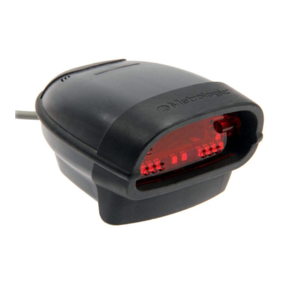
ODEL HARACTERISTICS IS1650 S CANNER Components Figure 1. Scanner Components Item Description Red Window LED Aperture Blue LED See Visual Indicators (on page 23) White LED See Visual Indicators (on page 23) Yellow LED See Visual Indicators (on page 23) -
Page 13: Dimensions
ODEL HARACTERISTICS IS1650 S CANNER Dimensions Figure 2. Scanner Dimensions Figure 3. M3 Mounting Hole Dimensions Caution: " The depth of each mounting hole is 12 mm (0.5 ). For fixed mount, the mounting " screws should not be over-tightened or go deeper than 10 mm (0.4 ) passing the bottom surface of the unit. -
Page 14: B M C
ODEL HARACTERISTICS IS1650 S CANNER Caution and Serial Number Labels Each scanner has a label located on the bottom of the unit. This label provides the unit’s model number, date of manufacture, serial number, CE and caution information. The following figure gives an example of the label/text and the location. -
Page 15: Installation
Figure 5. Figure 6. Disconnecting Before removing the cable from the scanner, Metrologic recommends that the power on the host system is off and the power supply has been disconnected from the PowerLink cable. Figure 7. Releasing the PowerLink Cable Locate the small ‘pin-hole’... -
Page 16: Cable Installation (Interface Specific)
AC power outlet. The IS1650 will start to initialize. All LEDs (yellow, white, and blue) will light for approximately two seconds then start to alternately flash. When the scanner has finished initializing the LEDs will stop flashing and the unit will beep three times indicating that the scanner is ready for use. -
Page 17: Keyboard Wedge Is1650-47
Connect the power supply transformer to an appropriate AC power outlet. The IS1650 will start to initialize. All LEDs (yellow, white, and blue) will light for approximately two seconds then start to alternately flash. When the scanner has finished initializing the LEDs will stop flashing and the unit will beep three times indicating that the scanner is ready for use. -
Page 18: Stand Alone Keyboard Is1650-47
Figure 10. power outlet. The IS1650 will start to initialize. All LEDs (yellow, white, and blue) will light for approximately two seconds then start to alternately flash. When the scanner has finished initializing the LEDs will stop flashing and the unit will beep three times indicating that the scanner is ready for use. -
Page 19: Rs485 Is1650-106
Turn off the host device. Plug the male 10-pin RJ45 end of the MVC cable into the 10-pin socket on the IS1650. There will be an audible click when the connector lock engages. Connect the other end of the MVC cable to the host device. -
Page 20: Low Speed Usb Is1650-38 (Integrated)
As a default, the IS1650-38 leaves the factory with USB Keyboard Emulation Mode enabled. For information on configuring the IS1650-38 for USB Serial Emulation... -
Page 21: Flex Stand Installation
TAND NSTALLATION PTIONAL Metrologic provides two #8 wood screws for securing the stand base to the counter top. The following figure provides the pilot hole dimensions for securing the stand base. Figure 13. Stand Base Hole Pattern (Not to Scale) - Page 22 NSTALLATION TAND NSTALLATION PTIONAL Figure 14. Assembling the Stand...
-
Page 23: Scanner Configuration Configuration Modes
ONFIGURATION ODES The IS1650 Series scanner has three modes of configuration. • Bar Codes The IS1650 can be configured by scanning the bar codes included in the Metrologic Single-Line Configuration Guide ( 00-02544) or the MLPN Supplemental Configuration Guide ( 00-02281). -
Page 24: Upgrading The Firmware
CANNER ONFIGURATION The IS1650 is part of Metrologic's line of scanners with flash upgradeable firmware. The upgrade process requires a new firmware file supplied to the customer by a customer service representative and Metrologic's MetroSet2 software . A personal computer running Windows 95 or greater with an available RS232 serial or USB port is also required to complete the upgrade. -
Page 25: Scanner Operation
When scanner successfully reads the bar code it will beep once, the white LED will flash and the decoded data will be transmitted to the host. Single Trigger Mode, Out-of-Stand * The IS1650 can switch into different modes of operation using the MetroSet2 Software or Area Imaging Supplemental Guide (00-02281). -
Page 26: Audible Indicators
UDIBLE NDICATORS When the IS1650 is in operation, it provides audible feedback. These sounds indicate the status of the scanner. Eight settings are available for the tone of the beep (normal, six alternate tones and no tone). To change the tone, refer to the MetroSelect Single-Line Configuration Guide ( 00-02544) or MetroSet2’s... -
Page 27: Visual Indicators
PERATION ISUAL NDICATORS The IS1650 has three LED indicators (yellow, white and blue) located on the top of the scanner. When the scanner is on, the flashing or constant activity of the LEDs indicates the status of the current scan and the scanner. -
Page 28: Failure Modes
CANNER PERATION AILURE ODES Long Razzberry Tone – During Power Up Failed to initialize or configure the scanner. If the scanner does not respond after reprogramming, return the scanner for repair. Short Razzberry Tone – During Scanning An invalid bar code has been scanned when in configuration. -
Page 29: Depth Of Field By Minimum Bar Code Element Width
PDF, 2D or OCR fonts without the proper licenses. Desired licenses can be specified at the time of sale or call a Metrologic representative for more information. Standard models ship with the ability to read all 1D, PDF and 2D bar codes. -
Page 30: Ir Activation Range
IR A CTIVATION ANGE The IS1650 has a built in object detection sensor that instantly turns on the scanner when an object is presented within the scanner’s IR activation Area. Figure 18. IR Activation Area Specifications are subject to change without notice... -
Page 31: Maintenance Daily Maintenance
AINTENANCE AILY AINTENANCE Smudges and dirt on the unit's window can interfere with the unit's performance. If the window requires cleaning, use only a mild glass cleaner containing no ammonia. When cleaning the window, spray the cleaner onto a lint free, non- abrasive cleaning cloth then gently wipe the window clean. -
Page 32: Troubleshooting Guide
ROUBLESHOOTING UIDE The following guide is for reference purposes only. Contact a Metrologic representative at 1-800-ID-Metro or 1-800-436-3876 to preserve the limited warranty terms. All Interfaces IS1650 Series Troubleshooting Symptom / Solution Chart Symptoms Possible Causes Solution No power is being... - Page 33 ROUBLESHOOTING UIDE Symptoms Possible Causes Solution The unit powers The beeper is up, but does not Enable the beeper and select a disabled and no tone beep when bar tone. is selected. code is scanned. UPC/EAN, Code 39, interleaved 2 The unit powers The bar code of 5, Code 93, Code 128, Codabar...
- Page 34 ROUBLESHOOTING UIDE Symptoms Possible Causes Solution The bar code may Check if it is a check have been printed digit/character/or border problem. incorrectly. The unit beeps at some bar The scanner is not codes and NOT configured correctly Check if check digits are set for others of the for this type of bar properly.
- Page 35 ROUBLESHOOTING UIDE Symptoms Possible Causes Solution Alpha Enable Caps Lock detect setting The computer is in characters show of the scanner to detect if the PC Caps Lock mode. as lower case. is operating in Caps Lock. Everything These characters works except for may not be supported Try operating the scanner in Alt...
-
Page 36: Default Settings
EFAULT ETTINGS Many functions of the scanner can be “configured” – that is, enabled or disabled. The scanner is shipped from the factory configured to a set of default conditions. The default parameter of the scanner has an asterisk (*) in the charts on the following pages. - Page 37 EFAULT ETTINGS PARAMETER DEFAULT RS232 RS485 & KEYBOARD Maxicode Aztec Postals Mod 43 Check on Code 39 MSI-Plessy 10/10 Check Digit MSI-Plessy Mod 10 Check Digit Paraf Support ITF ITF Symbol Lengths Variable Symbol Length Lock None Beeper tone Normal Before Beep/transmit sequence transmit...
- Page 38 EFAULT ETTINGS PARAMETER DEFAULT RS232 RS485 & KEYBOARD Transmit lead zero on UPC-E Transmit UPC-A number system Transmit UPC-A Manufacturer ID# Transmit UPC-A Item ID# Transmit Codabar Start/Stop Characters CLSI Editing (Enable) Transmit Mod 43 Check digit on Code 39 Transmit Mod 10/ITF Transmit MSI-Plessy Parity...
- Page 39 EFAULT ETTINGS PARAMETER DEFAULT RS232 RS485 & KEYBOARD XON/XOFF Handshaking ACK/NAK Two Digit Supplements Five Digit Supplements Bookland 977 (2 digit) Supplemental Requirement Supplements are not Required Two Digit Redundancy Five digit Redundancy Coupon Code 128 † Configurable Code Lengths 7 avail †...
-
Page 40: Scanner And Cable Terminations
CANNER AND ABLE ERMINATIONS CANNER INOUT ONNECTIONS The IS1650 scanner interfaces IS1650-14 terminate to a 10-pin, RJ45 RS232 Female Socket. The serial Function number label indicates the Ground interface enabled when the RS232 Transmit Output scanner is shipped from the factory. - Page 41 CANNER AND ABLE ERMINATIONS CANNER INOUT ONNECTIONS IS1650-38 Low Speed USB Function Ground RS232 Transmit Output RS232 Receive Input RTS Output CTS Input USB D+ V USB USB D- +5VDC Shield Ground IS1650-40 Full Speed USB Function Ground RS232 Transmit Output...
-
Page 42: Cable Connector Configurations
CANNER AND ABLE ERMINATIONS ABLE ONNECTOR ONFIGURATIONS “Standard” PowerLink Cable 59-59000-3, Straight Function Shield Ground RS232 Transmit Output RS232 Receive Input DTR Input/Light Pen Source Power/Signal Ground Reserved CTS Input 9-Pin D-Type Connector RTS Output +5VDC Stand Alone PowerLink Keyboard Cable 59-59020-3, Straight Function... - Page 43 PC Clock No Connect Metrologic will supply an adapter cable with a 5-pin DIN male connector on one end and a 6-pin mini DIN female connector on the other. According to the termination required, connect the appropriate end of the adapter cable to the PowerLink cable, leaving the necessary termination exposed for connecting to the keyboard and the keyboard port on the PC.
- Page 44 EGULATORY OMPLIANCE Safety ITE Equipment IEC 60950-1, EN 60950-1 Class 1 LED Product: IEC 60825-1:1993+A1+A2, EN 60825-1:1994+A1+A2 Caution Use of controls or adjustments or performance of procedures other than those specified herein may result in hazardous radiation exposure. Under no circumstances should the customer attempt to service the LED scanner.
-
Page 45: Class A Devices
EGULATORY OMPLIANCE Emissions FCC Part 15, ICES-003, CISPR 22, EN 55022 Immunity CISPR 24, EN 55024 NOTE: Immunity performance is not guaranteed for scanner cables greater than 3 meters in length when fully extended. Changes or modifications not expressly approved by the party responsible for compliance could void the user’s authority to operate the equipment. -
Page 46: Class B Devices
EGULATORY OMPLIANCE Changes or modifications not expressly approved by the party responsible for compliance could void the user’s authority to operate the equipment. Standard Europeo Attenzione Questo e’ un prodotto di classe A. Se usato in vicinanza di residenze private potrebbe causare interferenze radio che potrebbero richiedere all’utilizzatore opportune misure. -
Page 47: Patents
ATENTS For patent information, please refer to www.honeywellaidc.com/patents. -
Page 48: Limited Warranty
(2) year limited warranty from the date of manufacture. Metrologic warrants and represents that all IS1650 series scanners are free of all defects in material, workmanship and design, and have been produced and labeled in compliance with all applicable U.S. Federal, state and local laws, regulations and ordinances pertaining to their production and labeling. -
Page 49: Index
NDEX Dimensions ........9 AC ......... 3, 7, 12–16 Accessories ........3 Adapter........3, 39 EMC........7, 41 Aperture.........8 EMI ..........41 Audible Indicator....20, 23–24 Emissions........41 Bar Code ..... 6, 19, 28–31 Firmware ........20 Bar Code Element .......25 Full Speed......See USB Beep .... - Page 50 NDEX Light Levels ........7 Electrical........7 Light Source ........6 Environmental ......7 Low Speed ....... See USB Mechanical ........ 6 Operational........ 6 Stand ...... 4, 5, 17–18, 21 Stand Alone KB..See Interface Maintenance........27 ™ Swiftdecoder ....... 1 Meteor .........20 MetroSelect ....
- Page 52 August 2008 0 0 - 0 2 2 8 7 E...