Table of Contents
Advertisement
Uninterruptible Power Supply (UPS)
BU50SW/BU75SW/BU100SW/BU150SW
Instruction Manual
BU150SW
• This manual provides important safety-related information. Thoroughly read and understand
this manual before installing and using the product.
• Keep this manual in a convenient location so that you can refer to it whenever necessary.
Advertisement
Table of Contents

Related Manuals for Omron Powli BU50SW


Summary of Contents for Omron Powli BU50SW
- Page 1 Uninterruptible Power Supply (UPS) BU50SW/BU75SW/BU100SW/BU150SW Instruction Manual BU150SW • This manual provides important safety-related information. Thoroughly read and understand this manual before installing and using the product. • Keep this manual in a convenient location so that you can refer to it whenever necessary.
- Page 2 Introduction Features of this product Thank you for purchasing Omron's Uninterruptible Power Supply (UPS). ● The UPS protects computers and other devices from power failures, voltage variations, instantaneous voltage drops, and surge voltage such as that caused by lightning (a phenomenon in which extraordinary high voltage occurs instantaneously).
-
Page 3: Important Safety Instruction
IMPORTANT SAFETY INSTRUCTION 1. SAVE THESE INSTRUCTIONS. This manual contains important instructions for BU50SW/BU75SW/ BU100SW/BU150SW that should be followed when using the UPS and batteries. 2. SYMBOL This symbol indicates earth ground. This symbol indicates turning on UPS. This symbol indicates turning off UPS. 3. -
Page 4: Preparation For Operation
SW / BU SW / BU SW / BU Procedure from installation to operation Read “Safety precautions” Start Page iii Remove the product from the package and check the contents Page 1 Installation/connection Perform installation and connection Page 5 Are you Read “Using the UPS using UPS monitoring monitoring software and... -
Page 5: Table Of Contents
Table of Contents ■ Table of Contents ■ Introduction IMPORTANT SAFETY INSTRUCTION Safety precautions ............................. iii 1. Preparation ..............................1 Unpacking the product ........................1 Checking the contents .........................2 Name of each part ..........................2 Explanation of symbols used on unit ....................4 2. Installation and connection ..........................5 Precautions and notes on installation and connection ................5 Installation and connection ........................9 Connecting the equipment ........................10... -
Page 6: Safety Precautions
SW / BU SW / BU SW / BU Safety precautions Important information for safe operation is described. Be sure to read it before installation and start of use. ● The safety symbols and their meaning used in this manual are as follows: Warning Misuse may cause death or serious injury. - Page 7 Safety precautions Caution (for installation and connection) Connect the unit to a wall outlet with the proper current capacity, as follows: 8A or more (BU50SW), 10A or more (BU75SW), 12A or more (BU100SW), or 16A or more (BU150SW). ● Otherwise, the power cord may be heated. ●...
- Page 8 SW / BU SW / BU SW / BU Caution (for installation and connection) ● This UPS utilizes voltages that may be hazardous. Do not attempt to disassemble the unit The unit contains no user serviceable parts. Only factory service personnel may perform repairs.
- Page 9 Safety precautions Caution (for use) Do not allow the unit to come in contact with water. ● Doing so may cause an electric shock or a fi re. ● If the unit becomes wet, immediately stop using it, disconnect the AC input plug from the wall outlet, and have the unit inspected and repaired.
- Page 10 SW / BU SW / BU SW / BU Caution (for maintenance) When maintaining the connected equipment, turn OFF the power switch and disconnect the AC input plug. ● Even if you disconnect the AC input plug while the UPS is operating, the power output of this unit does not stop and power is supplied from the outlet during a power failure.
- Page 11 Safety precautions Caution (for battery replacement) Do not put the battery into fi re and do not break it. ● The battery may explode or leak dilute sulfuric acid. Do not use a new battery and an old battery at the same time. ●...
- Page 12 SW / BU SW / BU SW / BU Notes When moving the unit from a cold place to a warm place, leave it for several hours before using it. ● If the unit is promptly turned ON after being moved to a warmer place, condensation may form inside the unit and cause it to fail.
- Page 13 Safety precautions Notes Before stopping the commercial power to the unit, turn OFF the power switch of the unit. ● The unit enters Battery Mode when commercial power is stopped. If you frequently use the unit in Battery Mode, the battery life may be signifi cantly shortened. Check the operation beforehand if the unit is used in any mode other than “Output 100V mode”.
-
Page 14: Preparation
Instruction manual (Japanese and English versions) Warranty User registration card Label (How to determine operating status) AC input for 20A (NEMA L5-20P) 3P-2P conversion plug *1 Connector for remote ON/OFF Omron contact info label (2) UPS monitoring software BU50SW BU75SW BU100SW BU150SW Quick Install Guide... -
Page 15: Name Of Each Part
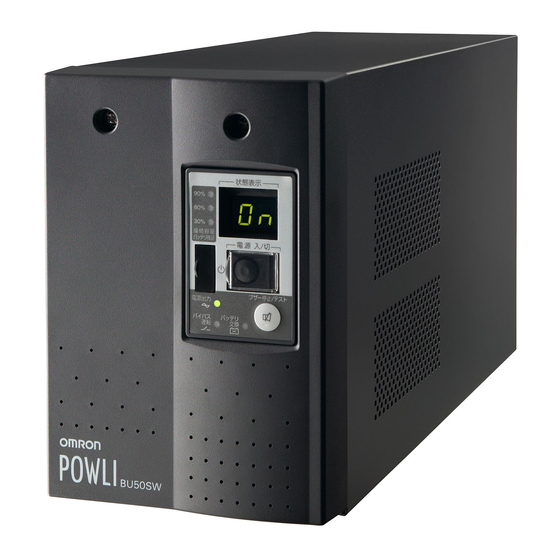
. Preparation Name of each par This section describes the name of each part of the UPS. For information on the function of each part, refer to "2. Installation and connection" on page 5 and "3. Operation" on page 16 that provides the details. Front view [ Enlarged view of the display panel ] A. -
Page 16: Rear View
SW / BU SW / BU SW / BU Rear view <BU50SW/BU75SW> A. RS232C connector B. Contact signal card C. Power supply output receptacles (Backup is performed during power failure.) D. Grounding terminal E. AC input overcurrent protection F. AC input cable G. -
Page 17: Explanation Of Symbols Used On Unit
. Preparation Explanation of symbols used on unit Symbol Description Start the UPS. Stop the UPS. Suspend a beep. UPS output power enabled, supplied by operating on line mode, battery mode. Bypass output “ON”. Additional battery unit connected to the UPS. (For BU100SW,BU150SW only.) Batteries at end of useful life, necessary to replace the batteries. -
Page 18: Installation And Connection
SW / BU SW / BU SW / BU Installation and connection Precautions and notes on installation and connection Caution (for installation and connection) Carry the unit considering its weight and balance, and place it on a stable and robust base. ●... - Page 19 . Installation and Connection Caution (for installation and connection) Do not exceed the ranges specifi ed for environmental conditions during use/storage. Do not install or store the unit in the places listed below. ● Do not store in places where the humidity is lower than 10% or higher than 90%. ●...
- Page 20 SW / BU SW / BU SW / BU Caution (for installation and connection) Do not connect a standalone transformer such as a voltage transformer or isolating transformer to the output side. ● Overcurrent may damage the UPS. ● There is no problem in connecting a transformer to the input side. Do not connect devices that cannot be used with commercial power supply.
- Page 21 . Installation and Connection Notes Do not connect the AC input plug of the unit to its Power Supply Output Receptacle during the Battery Mode. ● The unit may fail. Do not connect a page printer (such as a laser printer) to the unit. ●...
-
Page 22: Installation And Connection
SW / BU SW / BU SW / BU Installation and connection This section describes how to install the UPS. Do not use this unit in any position other than the “correct po- sitions” indicated in the illustration below. Note Before installing this device, make a record of the serial number of this device. -
Page 23: Connecting The Equipment
. Installation and Connection Connecting the equipment (1) Disconnect the AC Input Plugs of all devices you want to back up such as your PC and modems from a wall outlet (commer- Wall outlet cial power). (commercial power) (2) Connect devices you want to back up to the Power Supply Output Receptacles of the UPS. - Page 24 SW / BU SW / BU SW / BU (4) When the installation and connection is complete, connect the AC Input Plug of the UPS to a wall outlet (commercial power). <BU150SW> ● The BU150SW comes equipped with a 15A input plug (NEMA 5-15) at shipment. If this plug is used, make sure the capacity of the connected devices stays below the maxi- mum capacities shown in the table below.
- Page 25 . Installation and Connection <BU50SW/BU75SW/BU100SW> J [ h @ @ @ RS232C p t @ INPUT AC100V-120V 50/60Hz ˝ d ‹ 3P receptacle OUTPUT AC100-120V 50/60Hz 1ø o ˝ d ˝ ¯ 500VA / 350W 2P receptacle Grounding terminal In some cases, the AC plug may have no ground.
-
Page 26: Checking The Operation
SW / BU SW / BU SW / BU Checking the operation After you fi nish connecting devices to the unit, make sure the backup function operates properly. Check that the Battery Mode is performed normally according to the following procedure. (This operation check simulates a power failure by disconnecting the AC input plug from a wall outlet.) (1) Turn ON the unit's power switch. - Page 27 . Installation and Connection (5) In Battery Mode, check the unit's LED display and beep sound. Does the status indicator appear as one of those shown below? indicates blinking) Status indicator Beep Output Charging Description Intermittent Backup is operating due to power failure or AC input error. 4-second Discharging Output will stop if Battery Mode continues.
-
Page 28: Charging The Battery
SW / BU SW / BU SW / BU Charging the battery When you connect the AC input plug of this unit to a wall outlet (commercial power), the battery charging automatically starts regardless of whether the power switch is ON or OFF, and it is fully charged within 8 hours. -
Page 29: Operation
. Operation Operation Precautions and notes for operation Caution (for use) ● Doing so may cause an electric shock or a fi re. ● If the unit becomes wet, stop using it and have it inspected and/or repaired. For repair, contact us:____________ When the battery is dead, replace it immediately or stop using the unit. - Page 30 SW / BU SW / BU SW / BU Notes Before stopping the commercial power to the unit, turn OFF the power switch of the unit. ● The unit enters Battery Mode when commercial power is stopped. If you frequently use the unit in Battery Mode, the battery life may be signifi...
-
Page 31: Start And Stop Procedures And Basic Operation
. Operation Start and stop procedures and basic operation ● When the power switch is OFF and the AC input plug is connected to a commercial power supply : • The status indicator displays " ". • Power output is stopped. •... - Page 32 SW / BU SW / BU SW / BU ● Operation after a power failure • If a power failure or abnormal input power supply occurs, the UPS automatically switches to Battery Mode, continuing power output from the Power Supply Output Receptacles supplied from the battery. •...
-
Page 33: Interpreting Beeps And Displays
. Operation ● Connection capacity/battery level meter In normal operation, the power consumption of devices connected to the capacity/battery level meter is displayed as a percentage. BU50SW: Displayed in 3 levels, with 500VA/350W as 100%. BU75SW: Displayed in 3 levels, with 750VA/500W as 100%. BU100SW: Displayed in 3 levels, with 1000VA/700W as 100%. - Page 34 SW / BU SW / BU SW / BU indicates the display is OFF) indicates the display is ON) 3. Displays and beeps during power failure or AC input error indicates blinking) Bypass Power supply Battery Status operation Beep Charging Description Solution output...
- Page 35 . Operation indicates the display is OFF) indicates the display is ON) 4. Displays and beeps when there is an equipment failure (Continued) indicates blinking) Bypass Power supply Battery Status operation Beep Charging Description Solution output replacement indicator Moved to bypass operation due Displays the details of the error that occurred only while pressing the beep Continuous...
-
Page 36: Ups Functions
SW / BU SW / BU SW / BU UPS functions Suspending a beep When the beep is sounding, you can suspend it by pressing and holding the beep stop/test switch for 0.5 seconds or longer. Testing the UPS (Self-diagnosis test) This test performs a failure diagnosis on the unit and performs a simple test to check for battery deteriora- tion. -
Page 37: Description Of The Auto Battery Test Function
. UPS functions Description of the auto battery test function This test performs a failure diagnosis on the unit and checks for battery deterioration (it tends to detect bat- tery deterioration earlier than the self-diagnostic test does). This test is performed automatically. (You do not have to perform any special operations.) The test is performed once every 4 weeks after the AC input is connected to commercial power and power distribution begins. - Page 38 SW / BU SW / BU SW / BU ● Auto restart setting (setting switch 2 ) … Factory setting: OFF OFF: Automatically restarts when power is restored. After a power failure occurs and the UPS is shut down using the shutdown software or contact signal, the UPS automatically starts up and begins to output when the commercial power is restored.
- Page 39 . UPS functions AC input BS signal UPS output This timing is 10 ms or 10 sec. Shutdown delay timing Timing corresponds to the settings This delay corresponds to the settings for switch 7 . for switch 5 and switch 6 . The UPS delays the shutdown timing.
- Page 40 SW / BU SW / BU SW / BU 2. UPS operation mode settings The settings available for this operation are shown below. • Cold start ON/OFF setting When ON, it is possible to start up the unit even when there is no AC input plug. (It is not possible, however, to start up the unit by the remote signals.) Normal operation occurs when AC input is ON.
- Page 41 . UPS functions N o rm a l sta tus T h e re is A C inp ut (w h e n a th e sta tus ind ica tor is O N ) Pow e r sw itch “O F F ” (Sta tus N o. 2 ) (A ) (B ) Se tting m od e...
-
Page 42: Measuring The Backup Time
SW / BU SW / BU SW / BU Measuring the backup time How to measure backup time (1) When the AC input plug is connected to a wall outlet (commercial power), the battery automatically starts charging, taking up to 8 hours to complete (24 hours when an additional battery unit is connected). - Page 43 . Measuring the backup time * These backup times are for reference only. Times may vary according to battery life and external environmental conditions (temperature, etc.).
-
Page 44: Maintenance And Inspection
SW / BU SW / BU SW / BU Measuring and Inspection Caution (for maintenance) When maintaining the connected equipment, turn OFF the power switch and disconnect the AC input plug. ● Even if you disconnect the AC input plug while the UPS is operating, the power output of this unit does not stop and power is supplied from the outlet during a power failure. -
Page 45: Replacing The Battery
. Measuring and Inspection 3. Guidelines for how often to check the battery (measure the backup time) Check once a month Ambient temperature Check once every 6 months When 3 or more years have passed since purchase 20°C For the fi rst 3 years after purchase When 1.5 or more years have passed since purchase 30°C For the fi... - Page 46 SW / BU SW / BU SW / BU Caution (for battery replacement) Do not put the battery into fi re and do not break it. ● The battery may explode or leak dilute sulfuric acid. Do not use a new battery and an old battery at the same time. ●...
- Page 47 . Measuring and Inspection ➀ Turn the 2 screws that fi x the plate cover counterclockwise to remove them. ➁ ➂ Pull the plate cover towards you and lift it up to remove it. Remove the 2 screws. Hold the pullout label at the bottom of the battery pack and remove the battery pack. Do not hold the connector or cable of the battery pack.
- Page 48 SW / BU SW / BU SW / BU ➀ Insert a new battery into the UPS as far as it will go. ● Replacement battery pack For BU50SW/BU75SW: Model BP70XS For BU100SW: Model BP100XS For BU150SW: Model BP150XS Attach the plate cover. ➁...
- Page 49 . Measuring and Inspection Attach the front panel. Insert the lug at the bottom of the front panel into the hole in the main body ➀ and push it towards the main body. ➁ ➂ Use a screwdriver to securely tighten (clockwise) the 2 screws at the top of the front panel. Battery replacement is now complete.
-
Page 50: Replacing The Fan
SW / BU SW / BU SW / BU Replacing the fan The fan in the unit has an expected lifespan of approximately 5 years. Replace it when the Error Lamp is lit and the fan is stopped. Caution When this product is used in compliance with UL standards or CE marking, do not replace the fan. -
Page 51: Cleaning
. Measuring and Inspection ➁ While pressing down on the tip of the fan connector ➀, pull it toward you to disconnect it. The beep stops, and the error lamp turns OFF. ➂ Insert the new fan connector until it clicks into place. The beep stops, and the "EF"... -
Page 52: Using The Ups Monitoring Software And Contact Signal
(Note 5) (10.3, 10.4) Note 1: The most recent version can be downloaded from our homepage (http://www.omron.co.jp/ese/). Note 2: Files cannot be automatically saved. Note 3: To automatically stop the UPS, it may be necessary to change the PC’s BIOS settings. -
Page 53: When Using The Included Ups Monitoring Software To Perform Auto Shutdown
. Using the UPS monitoring software and contact signal When using the included UPS monitoring software to perform auto shutdown "PowerAct Pro" UPS monitoring software The included "PowerAct Pro" UPS monitoring software allows you to automatically save fi les and perform shutdown processing of your PC when a power failure occurs. -
Page 54: When Performing Auto-Save Functions Using The Ups Service In Windows Server 2003/Xp/2000 + Ups Service Driver
SW / BU SW / BU SW / BU Explanation Scheduled operation using the UPS monitoring software ● When performing scheduled operation in which the UPS is stopped and a device such as a breaker is used to stop the UPS at the same time that commercial power stops, specify a period of no more than 3 months for the start of the next operation. -
Page 55: When Performing Auto-Save Functions Using The Standard Ups Service In Windows Server 2003/Xp/2000/Nt
. Using the UPS monitoring software and contact signal When performing auto-save functions using the standard UPS service in Windows Server 2003/XP/2000/NT When using in combination with the BUC26 cable (sold separately), the OS standard UPS service in Windows Server 2003/XP/2000/NT can be used. When there is a power failure, the computer can be shut down. - Page 56 SW / BU SW / BU SW / BU ● How to set up UPS service (shut down Windows when low battery level is detected) 1) Double-click the "Power supply options" icon in "Control Panels". 2) Click the "UPS" tab in the "Power supply options" window. Click the "Select (S)"...
-
Page 57: Stopping The Ups
. Using the UPS monitoring software and contact signal 5) Click the "OK" button in the "Power supply options" window. Setup is complete. When a power failure occurs, Windows shutdown starts once the Low battery level signal is detected. If the power is restored before the Low battery level signal is detected, Windows shutdown does not start and the normal monitoring state is restored. - Page 58 SW / BU SW / BU SW / BU 2) In the "Warning" box, place a check mark in the box to the left of "Time from when battery drive starts until warning is issued (M)" by clicking on it. In the window to the right, set the amount of time to wait before starting Windows shutdown after a power failure occurs.
- Page 59 . Using the UPS monitoring software and contact signal <When using the Windows NT standard UPS service> ● How to set up UPS service 1) Double-click the "UPS" icon in "Control Panels". 2) Insert a check mark in the checkbox to the right of "Port where UPS is installed (U)..." by clicking on In the setting fi...
-
Page 60: Contact Signal
SW / BU SW / BU SW / BU Note Please note that in the case of incorrect interface voltage signal settings, Windows NT will not receive the signal from the UPS and the UPS will not stop when there is a power failure. Failure to put check marks in the boxes will lead to the same result. - Page 61 . Using the UPS monitoring software and contact signal 2. Input of the UPS Stop Signal (BS) BS-COM UPS stops Stops the output of the UPS after the time period specifi ed by the “power output stop delay time setting” (setting switches 5 and 6 ) has elapsed.
- Page 62 SW / BU SW / BU SW / BU ● Output delay time setting for backup signal output (BU) BL-COM ON when the battery is low Continues during a power failure, and turns ON (OFF). By setting the contact signal card’s setting switch as shown in the table on the right, the length of time from when the power failure occurs until the power failure signal is output can be delayed be-...
- Page 63 . Using the UPS monitoring software and contact signal How to insert/remove the contact signal card (1) Turn OFF the power switch, remove the top and bottom screws (2 screws) of the contact signal connec- tor on the back of the unit, and carefully remove the contact signal card. (2) After changing the settings, carefully reinsert the contact signal card and securely tighten the 2 screws.
- Page 64 SW / BU SW / BU SW / BU 7. Contact Signal ratings ● Signal output (BL, TR, BU, WB, BU) ● UPS Stop Signal input (BS) Photo coupler ratings Input voltage HIGH(ON) 5 to 12 VDC Appliable voltage: 35 VDC or less LOW(OFF) 0.7 VDC or less Maximum current: 20 mA...
- Page 65 . Using the UPS monitoring software and contact signal 10. Precautions and notes for the use of the Contact Signal Notes ● When connecting a device such as a relay that generates counter electromotive force to the signal output circuit, connect diodes that prevent counter electromotive force to both ends of the relay. Explanation ●...
-
Page 66: Using An Snmp/Web Card
SW / BU SW / BU SW / BU Using an SNMP/Web card Adding an SNMP/Web card An SNMP/Web card can be loaded into the card slot on the back of the unit. Remove the contact signal card that the unit came equipped with, and plug the SNMP/Web card in its place. Store the removed contact sig- nal card in a safe place. -
Page 67: Snmp/Web Card Outline
Max OS X v10.3*/Server 10.3 (*1) Max OS X v10.4*/Server 10.4 (*1) Compatible only with Macintosh computers equipped with PowerPC CPU. For more details, refer to the instruction manual included with the SNMP/Web card. The most recent fi rmware can be downloaded from our homepage(http://www.omron.co.jp/ese/). -
Page 68: Extending The Backup Time
SW / BU SW / BU SW / BU Extending the backup time Connecting an additional battery unit (BU100SW/ BU150SW only) You can extend the backup time by connecting an additional optional battery unit to the UPS. Additional battery unit You can connect only one additional battery unit. -
Page 69: Troubleshooting
. Troubleshooting Troubleshooting Perform the checks shown below if the unit is operating abnormally. If the unit continues to operate abnormally, please contact our Electronic System & Eqiuipment customer support center at _____. Problem Check and remedy UPS does not operate. 1. -
Page 70: References
SW / BU SW / BU SW / BU Reference A. Specifi cations BU50SW BU75SW BU100SW BU150SW Method Operation method Full-time inverter supply method Connectable devices PC, display, and peripherals Input Nominal Input voltage 100/110/115/120 VAC 75 4 to 144 4V AC (with 90% or less connection load) Input voltage range 85 4 to 144 4V AC (with 90% or less connection load) Input frequency... -
Page 71: Dimensions
Reference B. Dimensions ● BU50SW/BU75SW /BU100SW (unit : mm / Tolerance : ±1mm) ● BU150SW (unit : mm / Tolerance : ±1mm) -
Page 72: Circuit Block Diagram
SW / BU SW / BU SW / BU C. Circuit block diagram Commercial power bypass output Power supply Rectifier Power relay Inverter (high power Noise supply Filter (sine 100V AC factor output: filter input wave) converter) Input overcurrent 100V AC protection Output switching... -
Page 73: List Of Ups Monitoring Software Functions
Reference E. List of UPS monitoring software functions Possible Limited Network management applications SNMP management applications General applications Software title (Advanced functions, (Advanced functions, (Simple functions, standalone) network support) network support) Function UPS service driver SNMP/Web card Standard OS UPS service PowerAct Pro Required separately available option BUC26... - Page 74 No part or whole of this manual may be reproduced without permission. The contents of this manual are subject to change without notice. OMRON Corporation K1L-D-05095G...