Table of Contents
Advertisement
Uninterruptible Power Supply
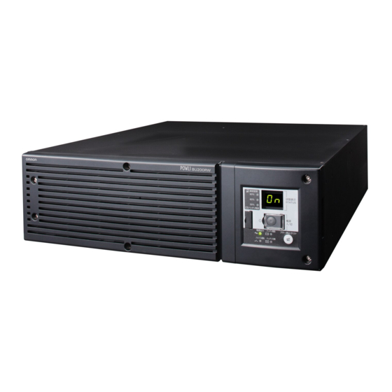
BU75RW/BU100RW/BU200RW/BU300RW
Instruction Manual
• This manual provides important safety-related information. Thoroughly read and understand
this manual before installing and using the product.
• Keep this manual in a convenient location so that you can refer to it whenever necessary.
• The contents of this manual are subject to change without notice.
BU300RW
Advertisement
Table of Contents

Related Manuals for Omron Powli BU75RW


Summary of Contents for Omron Powli BU75RW
- Page 1 Uninterruptible Power Supply BU75RW/BU100RW/BU200RW/BU300RW Instruction Manual BU300RW • This manual provides important safety-related information. Thoroughly read and understand this manual before installing and using the product. • Keep this manual in a convenient location so that you can refer to it whenever necessary. •...
-
Page 2: Introduction
Introduction Features of this product Thank you for purchasing Omron's Uninterruptible Power Supply (UPS). The UPS protects computers and other devices from power failures, voltage variations, in- stantaneous voltage drops, and surge voltage such as that caused by lightning (a phenom- enon in which extraordinary high voltage occurs instantaneously). -
Page 3: Important Safety Instruction
IMPORTANT SAFETY INSTRUCTION 1. SAVE THESE INSTRUCTIONS. This manual contains important instructions for BU100RW/BU200RW/ BU300RW that should be followed when using the UPS and batteries. 2. SYMBOL This symbol indicates earth ground. This symbol indicates turning on UPS. This symbol indicates turning off UPS. 3. -
Page 4: Preparation For Operation
Procedure from installation to operation Read “Safety precautions” Start Page v Remove the product from the package and check the contents Page 1 Installation/connection Perform installation and connection Page 5 Are you Read “Using the UPS using UPS monitoring monitoring software and software or contact contact signal”... -
Page 5: Table Of Contents
Table of Contents Table of Contents Introduction ............................i IMPORTANT SAFETY INSTRUCTION ....................ii Safety precautions ..........................v 1. Preparation .............................1 1-1 Unpacking the product .......................... 1 1-2 Checking the contents ........................... 1 1-3 Name of each part ..........................2 1-4 Explanation of symbols used on unit ..................... -
Page 6: Safety Precautions
RW/BU RW/BU RWBU Important information for safe operation is described. Safety precautions Be sure to read it before installation and start of use. The safety symbols and their meaning used in this manual are as follows: Warning Misuse may cause death or serious injury. Caution Misuse may cause injury or property damage. - Page 7 Safety precautions Caution (for installation and connection) When an abnormality (unusual sound or smell) occurs, turn OFF the unit’s power switch to stop the output, and stop the supply of commercial power. For the BU75RW/BU100RW, disconnect the AC input plug from the wall outlet.
- Page 8 RW/BU RW/BU RWBU Caution (for installation and connection) Do not use the unit where the maximum temperature exceeds 40°C. The battery deteriorates rapidly. Doing so may cause a failure or malfunction of the unit. Do not exceed the ranges specifi ed for environmental conditions during use/storage.
- Page 9 Safety precautions Caution (for use) Do not allow the unit to come in contact with water. If you drop the unit, stop using it. Doing so may cause an electric shock or a fi re. If the unit becomes wet or is dropped, immediately stop using it, disconnect the AC input plug from the wall outlet (commercial power) or, when using the BU200RW/BU300RW, turn OFF the INPUT PROTECTION switch (input overcurrent protection switch) on the back of the unit, and have it inspected and repaired.
- Page 10 RW/BU RW/BU RWBU Caution (for maintenance) When maintaining the connected equipment, turn OFF the unit’s power switch to stop the output, and stop the supply of commercial power. (For the BU75RW/BU100RW, disconnect the AC input plug from the wall outlet. For the BU200RW/BU300RW, disconnect the AC input plug from the wall outlet (commercial power) or turn OFF the INPUT PROTECTION switch (input overcurrent protection switch) on the back of the unit.) Even if commercial power to the UPS is stopped while it is in operation, the power output of...
- Page 11 Safety precautions Notes When moving the unit from a cold place to a warm place, leave it for several hours before using it. If the unit is promptly turned ON after being moved to a warmer place, condensation may form inside the unit and cause it to fail.
- Page 12 RW/BU RW/BU RWBU Notes Before stopping the commercial power to the unit, turn OFF the power switch of the unit. The unit enters Battery Mode when commercial power is stopped. If you frequently use the unit in Battery Mode, the battery life may be signifi cantly shortened. If this unit is used with an inductive device such as a coil or motor, check the operation beforehand.
-
Page 13: Preparation
Support angles compatible with EIA/ 1 set 1 set 1 set 1 set JIS 19-inch racks Omron contact info label Battery replacement date label Control display panel explanation label Rubber feet for horizontal placement 4 per set 4 per set... -
Page 14: Name Of Each Part
.Preparation Name of each part This section describes the name of each part of the UPS. For information on the function of each part, refer to "2. Installation and connection" on page 5 and "3. Operation" on page 25 that provides the details. Front view <BU75RW/BU100RW>... - Page 15 RW/BU RW/BU RW/BU Rear view <BU75RW/BU100RW> <BU200RW/BU300RW>...
-
Page 16: Explanation Of Symbols Used On Unit
.Preparation Explanation of symbols used on unit Symbol Description Start the UPS. Stop the UPS. Suspend a beep. UPS output power enabled, supplied by operating on line mode, battery mode. Bypass output “ON”. Additional battery unit connected to the UPS. Batteries at end of useful life, necessary to replace the batteries. -
Page 17: Installation And Connection
Installation and connection Precautions and notes on installation and connection Caution (for installation and connection) Two or more people should work together to carry, unpack and install the BU200RW/BU300RW. Because the unit is heavy, you may injure yourself or drop the unit, or it may fall over. Carry the unit considering its weight and balance, and place it on a stable and robust base. - Page 18 .Installation and connection Caution (for installation and connection) power capacity of 24A or more. When using the 30A plug (NEMAL5-30P) that is connected to the BU300RW at shipment, the maximum capacity connectable to the output is approximately 2400VA/1920W. When the power consumption exceeds this capacity, the input voltage becomes larger than 30A, which may lead to overheating or fi...
- Page 19 RW/BU RW/BU RW/BU Caution (for installation and connection) Do not connect a standalone transformer such as a voltage transformer or isolating transformer to the output side. Overcurrent may damage the UPS. There is no problem in connecting a transformer to the input side. Do not connect devices that cannot be used with commercial power supply.
- Page 20 .Installation and connection Notes Check system operation beforehand if the unit is used in combination with a device whose power supply frequency fluctuates widely, such as a personal electric generator. The unit automatically recognizes the input power frequency when input power is supplied.If the unit is connected when the input power frequency is not stable at the rated level, the unit may misidentify the power supply frequency and may fail to operate normally.
-
Page 21: Installation And Connection
RW/BU RW/BU RW/BU Installation and connection The UPS permits the following installing methods. Choose the one best suited for the environment. 2-2-1. Rackmount installation 2-2-2. Stationary installation Horizontal Upright intatllation Do not use this unit in any position other than the “correct positions” indicated in the illustration below. Note Before installing this device, make a record of the serial number of this device. - Page 22 .Installation and connection < BU200RW/BU300RW > Caution When connecting an additional battery unit (BUM300R), make sure it is installed below the BU200RW/BU300RW UPS.
- Page 23 RW/BU RW/BU RW/BU 2-2-1. Rackmount installation (EIA /JIS 19-inch rack/server rack) Caution When performing rack installation, ensure that the UPS is supported and stabilized by using both the support angles and the table clamps that were included. When connecting a battery unit and/or adding another battery unit, be sure to place the battery unit in a position lower than the main unit.
- Page 24 .Installation and connection (2) Adjust the length of support angles to suit the server rack, and then securely tighten the screws that were half-tightened in step 1. (3) Use the 4 included rack fi xing screws and nuts (medium-sized) to securely fasten the front (the side displaying “L”...
- Page 25 RW/BU RW/BU RW/BU (5) Place the UPS on the support angles and push it completely into the rack , and use the 2 included unit fi xing screws and unit fi xing nuts to securely fasten the ear brackets to the server rack.
- Page 26 .Installation and connection 2-2-2. Stationary installation Perform installation only as shown in the diagrams below. Horizontal installation Attach the included rubber feet for horizontal installation (14.5 mm depth) to the round stickers on the unit (4 locations) and position the unit horizontally. For stationary horizontal installation, make sure that this product does not slide or fall.
-
Page 27: Connecting The Equipment
RW/BU RW/BU RW/BU Connecting the equipment Caution Do not connect devices with rated voltage of 100 to 120 VAC or higher. The rated output voltage of this device is 100 to 120 VAC. Overcurrent may damage the connected devices. Before connecting the BU200RW and BU300RW to commercial power, make sure the input terminal block cover is attached. - Page 28 .Installation and connection Output ON Output OFF Power supply output group A Time setting Time setting Power supply output group B Time setting Time setting Power supply output group C 2-3-1. Connecting a device to the power supply output (BU75RW/BU100RW) (1) Connect devices (computer, server, peripherals, etc.) that require backup to the power supply out- put receptacle on the back of the unit.
- Page 29 RW/BU RW/BU RW/BU 2-3-2. Connecting a device to the power supply output (BU200RW/BU300RW) (1) Connect devices (computer, server, peripherals, etc.) that require backup to the power supply out- put receptacle on the back of the unit. Make sure that the total capacity of the devices connected to the output receptacle does not exceed the output rated capacity of the BU200RW/BU300RW.
-
Page 30: Connecting The Ac Input
.Installation and connection Connecting the AC input When installation and connection are complete, connect the unit’s AC input to a commercial power source. Caution Make sure to connect the AC input plug of the unit into a wall outlet (commercial power) with rated input voltage (100V to 120V AC). Connecting to a wall outlet (commercial power) of a different rated voltage may result in fi... - Page 31 RW/BU RW/BU RW/BU Caution When using the 15A plug (NEMA 5-15P) with the BU200RW, the maximum capacity connectable to the output is approximately 1100VA/880W. When the power consumption exceeds this capacity, the input voltage becomes larger than 15A, which may lead to overheating or fi re. When the overload display appears (“...
- Page 32 .Installation and connection <BU200RW/BU300RW> BU300RW BU200RW 3P receptacle 100 VAC 3P receptacle 3P receptacle Connect the grounding wire to earth in building BU300RW Input plug (L5-30P) Caution (Front view) When one wire is used to ground the AC input power supply, make sure to use this unit's N terminal (phase) side as the ground.
- Page 33 RW/BU RW/BU RW/BU Replacing the BU200RW/BU300RW AC input cable (1) Remove the terminal-cover at AC input. (Two screws) unscrew these Terminal-cover (2) Remove screws at terminals (L, N, G) connecting the cable to the terminals and remove the old AC input cable. (3) Run the newly connected cable through the included AC input terminal cover.
-
Page 34: Checking The Operation
.Installation and connection Checking the operation When you fi nish connecting the unit, confi rm that the backup operation works properly. Check that the Battery Mode is performed normally according to the following procedure. (In this operation check, the effects of a power failure are reproduced by disconnecting the AC input plug from the wall outlet (commercial power) or, when using the BU200RW/BU300RW, by turning OFF the INPUT PROTECTION switch (input overcurrent protection switch).) (1) Turn ON the unit's power switch. - Page 35 RW/BU RW/BU RW/BU (5) In Battery Mode, check the unit's LED display and beep sound. Does the status indicator appear as one of those shown below? indicates blinking) Status indicator Beep Output Charging Description Intermittent Backup is operating due to power failure or AC input er- 4-second Discharging ror.
-
Page 36: Charging The Battery
.Installation and connection Charging the battery For the BU75RW/BU100RW: The battery automatically starts charging when the AC input plug is connected to a wall outlet (commercial power). (This occurs regardless of whether the power switch is ON or OFF.) The charging takes 8 hours to complete (24 hours when additional battery unit is connected). For the BU200RW/BU300RW: The battery automatically starts charging when the AC input plug is connected and the INPUT PROTECTION switch (input overcurrent protection switch) is turned ON. -
Page 37: Operation
Operation Precautions and notes for operation Take notice of following items during operation. Caution (for use) Do not allow the unit to come in contact with water. Doing so may cause an electric shock or a fi re. If the unit becomes wet, immediately stop using it, disconnect the AC input cable from the wall outlet (commercial power) or, when using the BU200RW/BU300RW, turn OFF the INPUT PRO- TECTION switch (input overcurrent protection switch) on the back of the unit, and have it in- spected and repaired. - Page 38 .Operation Notes Before stopping the commercial power to the unit, turn OFF the power switch of the unit. The unit enters Battery Mode when commercial power is stopped. If you frequently use the unit in Battery Mode, the battery life may be signifi cantly shortened. Take measures for handling unforeseen accidents, such as data backup and system redundancy.
-
Page 39: Start And Stop Procedures And Basic Operation
RW/BU RW/BU RW/BU Start and stop procedures and basic operation When the power switch is OFF and the AC input plug is connected to a commercial power supply: (Turn ON the INPUT PROTECTION switch (input overcurrent protection switch) on the back of the BU200RW/BU300RW.) •... - Page 40 .Operation Operation after a power failure • If a power failure or abnormal input power supply occurs, the UPS automatically switches to Battery Mode, continuing power output from the Power Supply Output Receptacles supplied from the battery. • The status is displayed and the beeper sounds intermittently to alert the user. Setting switch can be used to turn the beeper ON/OFF.
- Page 41 RW/BU RW/BU RW/BU Operation during recovery from a power failure • The unit automatically resumes output via commercial power if it recovers from a pow er failure/input power supply error while it is providing power supply output. The spent battery starts charging.
-
Page 42: Interpreting Beeps And Displays
.Operation Interpreting beeps and displays indicates the display is OFF) 1. Displays and beeps in normal operation indicates the display is ON) (1) When power switch is OFF indicates blinking) Bypass Power supply Battery Status operation output Beep Charging Description Solution replacement indicator... - Page 43 RW/BU RW/BU RW/BU indicates the display is OFF) 4. Displays and beeps when there is an equipment failure indicates the display is ON) (1) When power switch is ON indicates blinking) Bypass Power supply Battery Status operation Beep Charging Description Solution output replacement...
- Page 44 Contact the shop of purchase or the Continuous of the error are displayed. OMRON Electronic Systems & Equipments Customer Support Center at: __________. Stopped charging due to Displays the details of the error that...
-
Page 45: Ups Functions
UPS functions Suspending a beep When the beep is sounding, you can suspend it by pressing and holding the beep stop/test switch for 0.5 seconds or longer. Self-diagnosis test This test performs a failure diagnosis on the unit and performs a simple test to check for battery dete- rioration. -
Page 46: Description Of The Auto Battery Test Function
. UPS functions Description of the auto battery test function This test performs a failure diagnosis on the unit and checks for battery deterioration (it tends to detect battery deterioration earlier than the self-diagnostic test does). This test is performed automatically. (You do not have to perform any special operations.) The test is performed once every 4 weeks after the AC input is connected to commercial power and power distribution begins. - Page 47 RW/BU RW/BU RW/BU Setting for beeper sound in the event of power failure, etc. (setting switch … Factory setting: OFF OFF: The beeper sounds when an alarm is necessary. The beeper does not sound for backup operation or battery replacement. The beeper sounds for other errors (connection capacity exceeded, operation error, etc.).
- Page 48 . UPS functions ) … Factory setting: OFF Auto startup mode setting (setting switch OFF: (Mode A) After UPS stopped, the UPS is automatically started immediately when “ON” is detected for the AC input. ON: (Mode B) After UPS stopped, the UPS is automatically started in the AC input’s “OFF to ON”...
- Page 49 RW/BU RW/BU RW/BU (2) When BS signal is used to shut down the UPS when AC input is ON 1 sec AC input Starts up when BS signal turns OFF BS signal Power output (Setting switch 4 OFF: Starts up when AC input Mode A) turns from OFF to ON Power output...
- Page 50 . UPS functions AC input plug selection (setting switch … Factory setting: Refer to the table below. Setting switch Setting switch BU75RW BU100RW BU200RW BU300RW Factory setting Factory setting Factory setting 30A or power switchboard con- Factory setting nection 35A or greater power switchboard connection BU75RW Use the factory settings for 7 and 8 (both OFF).
- Page 51 RW/BU RW/BU RW/BU 4-4-2. UPS operation mode settings 1. Settable items and explanations There are 4 items to select. 1) Cold start ON/OFF setting 2) Output voltage setting 3) Power output stop delay time setting 4) Signal input/output test The settings available for this operation are shown below. 1) Cold start ON/OFF setting •...
- Page 52 . UPS functions 4) Signal input/output test (BL/TR/BU/WB/BS/remote) Four types of output signal can be forcibly turned ON. The ON/OFF state of two types of input signal can be checked with the status indicator and the beeper. Signal input/output test end Signal input test While the signal is being Signal input/output test start...
- Page 53 RW/BU RW/BU RW/BU 2. Settings The UPS operation mode can be set if the power switch is turned ON while the beeper stop switch is pressed. Note: While in setting mode, output from the power supply output is OFF even if the power switch is ON.
- Page 54 . UPS functions Turn ON the power switch while the beep stop/test switch is pressed. Normal status There is AC input Turn OFF the power switch. Power switch “OFF” (Status No. 2) Press and hold the beep stop/test switch (for more than 1 seconds). Press the beep stop/test switch (for less than 1 seconds).
-
Page 55: Measuring The Backup Time
Measuring the backup time How to measure backup time (1) BU75RW/BU100RW: Connect the AC input plug to commercial power and charge the battery for 8 hours (24 hours if additional battery unit is connected). BU200RW/BU300RW: Connect the AC input plug, turn ON the INPUT PROTECTION switch (input overcurrent protection switch) on the back of the unit, and charge the battery for at least 8 hours (24 hours if an additional battery unit is connected). - Page 56 . Measuring the backup time (3) Calculate the initial value of the backup time for the total capacity of the connected devices from the graph below. Graph of backup time (graph of initial values for products that have not been used at 20°C) The backup time becomes shorter than the graph (table) below when temperature is lower.
-
Page 57: Maintenance And Inspection
Maintenance and Inspection Caution (for maintenance) When maintaining the connected equipment, turn OFF the BU75RW/ BU100RW’s power switch and disconnect the AC input plug. For BU200RW/BU300RW, make sure to turn OFF the power switch and either disconnect the AC input plug or turn OFF the INPUT PROTECTION switch (input overcurrent protection switch). -
Page 58: Replacing The Battery
. Maintenance and Inspection 3. Guidelines for how often to check the battery (measure the backup time) Ambient temperature Check once every 6 months Check once a month 20°C For the fi rst 3 years after purchase When 3 or more years have passed since purchase 30°C For the fi... - Page 59 RW/BU RW/BU RW/BU A battery can present a risk of electrical shock and high short circuit current.The following pre- cautions should be observed when working on batteries: 1) Remove watches, rings, or other metal objects from the hands. 2) Use tools with insulated handles. 3) Wear rubber gloves and boots.
- Page 60 . Maintenance and Inspection Remove the battery pack by pulling on the pullout labels at the top and bottom of the battery pack. Caution: Do not hold the battery pack by the connector or cable. Use the red tape on top of the battery pack, which is 10 cm from the inner edge of the battery, to gauge how much further you need to pull the battery to remove it.
- Page 61 RW/BU RW/BU RW/BU Attach the plate cover. Insert the tab on the left side of the plate cover into the hole in the BU75RW/BU100RW , and push the plate cover toward the BU75RW/BU100RW. Securely tighten the screw that was removed from the right side of the plate cover. Tighten the screw.
- Page 62 . Maintenance and Inspection <After replacing the battery during operation...> If the battery replacement indicator is displayed and the beeper sounds before replacement, press the beeper stop/test button once to stop the beeper, and hold it for 5 sec. to perform a self-diagnostic test.
- Page 63 RW/BU RW/BU RW/BU Battery recycling The unit uses lead acid batteries, which are a valuable recyclable resource. Please recycle. For information on recycling, please contact our Electronic Systems & Equipments repair center. Procedure for recycling the battery <BU200RW/BU300RW> Use a screwdriver to loosen (turn counter-clockwise) the 4 screws at the top of the front panel of the unit, until they turn freely.
- Page 64 . Maintenance and Inspection Remove (turn counter-clockwise) the 2 screws on either side that hold the plate cover in place. Pull the right side of the plate cover towards you to remove it. Hold the pullout label at the bottom of the battery pack and remove the battery pack. Do not hold the connector or cable of the battery pack.
- Page 65 RW/BU RW/BU RW/BU Insert a new battery into the UPS as far as it will go. Replacement battery pack For BU200RW/BU300RW: Model BUB300R Attach the plate cover. Insert the lug at the left of the cover into the hole in the main body and push it towards the main body. Use a screwdriver to securely tighten (clockwise) the 2 screws you removed.
- Page 66 . Maintenance and Inspection Attach the front panel. Move the front panel in the right and push it towards the main body. Use a screwdriver to securely tighten (clockwise) the 4 screws at the top of the front panel. Tighten the 4 screws. Battery replacement is now complete.
-
Page 67: Replacing The Fan
RW/BU RW/BU RW/BU Replacing the fan The fan in the unit has an expected lifespan of approximately 5 years. Replace it when the Error Lamp is lit and the fan is stopped. Caution When this product is used in compliance with UL standards or CE marking, do not replace the fan. - Page 68 . Maintenance and Inspection Fan replacement procedure Use a screwdriver to loosen (turn counter-clockwise) and remove the cooling fan screws 4 screws. (The diagram shows the BU200RW/BU300RW rear cooling fan.) → Page 55 See also Loosen the 4 Phillips-type screws. While pressing down on the tip of the fan connector , pull it toward you to disconnect it.
-
Page 69: Cleaning
RW/BU RW/BU RW/BU Cleaning 1. Cleaning the UPS Moisten a soft cloth with water or detergent, squeeze it tightly, and wipe the product lightly. Do not use chemicals such as thinner and benzene. (They cause deformation or discoloration.) 2. Removing dust from the AC input plug, power supply output receptacles of the UPS Stop all the connected devices and the UPS and disconnect the AC input plug from a wall outlet (commercial power). -
Page 70: Using The Ups Monitoring Software And Contact Signal
→ 10.4) See 8-1 Note 1: The most recent version can be downloaded from our homepage (http://www.omron.co.jp/ese/). Note 2: Files cannot be automatically saved. Note 3: To automatically stop the UPS, it may be necessary to change the PC’s BIOS settings. - Page 71 Note 2: Only the battery capacity can be monitored. Note 3: This function can be used with Windows only. It cannot be used with Linux. Note 4: For the latest information, check our website at: http://www.omron.co.jp/ese/ Note 5: Compatible only with Macintosh computers equipped with PowerPC CPU.
-
Page 72: When Using The Included Ups Monitoring Software To Perform Auto Shutdown
. Using the UPS monitoring software and contact signal When using the included UPS monitoring software to perform auto shutdown When using PowerAct Pro “UPS monitoring software for Windows/Linux” "PowerAct Pro" UPS monitoring software The included "PowerAct Pro" UPS monitoring software allows you to automatically save fi les and perform shutdown processing of your PC when a power failure occurs.(It is possible to shut down multiple computers on the network.) Also, you can perform desired operation by setting the automatic start/stop of the UPS based on... - Page 73 RW/BU RW/BU RW/BU * When connecting 2 or more computers to the UPS Power cable Power cable LAN connection PC server 3 Power cable Network PC server 2 Power cable Switching hub PC server 1 Remote connection The Included connection cable (RS-232C or USB) UPS (Image shows BU300RW.) 7-1-2.
- Page 74 . Using the UPS monitoring software and contact signal Explanation Scheduled operation using the UPS monitoring software When performing scheduled operation in which the UPS is stopped and a device such as a breaker is used to stop the UPS at the same time that commercial power stops, specify a period of no more than 3 months for the start of the next operation.
-
Page 75: When Performing Auto-Save Functions Using The Ups Service In Windows Server 2003/Xp/2000 + Ups Service Driver
XP/2000 can be used. When there is a power failure, fi les can automatically be saved and the com- puter can be shut down. Check our website for the most recent version (http://www.omron.co.jp/ese/). 7-2-1. Connect the UPS to a computer. -
Page 76: When Performing Auto-Save Functions Using The Standard Ups Service In Windows Server 2003/Xp/2000/Nt
. Using the UPS monitoring software and contact signal When performing auto-save functions using the standard UPS service in Windows Server 2003/XP/2000/NT When using in combination with the BUC26 cable (sold separately), the OS standard UPS service in Windows Server 2003/XP/2000/NT can be used. When there is a power failure, the computer can be shut down. - Page 77 RW/BU RW/BU RW/BU 7-3-2. Perform UPS service setup. You need to make Windows settings in order to perform auto shutdown. There is no need to install software. <When using the Windows Server 2003/XP/2000 standard UPS service> Start up the computer after connecting it with the UPS. Perform "Log on to Windows"...
-
Page 78: Stopping The Ups
. Using the UPS monitoring software and contact signal 4) In the "UPS signal polarity" box, click on the boxes to the right of "Power supply failure/battery drive (P)" and "Low battery (L)" signals to insert check marks. Set the polarity for each signal to "Negative". Click the "End" button. 5) Click the "OK"... - Page 79 RW/BU RW/BU RW/BU How to set up UPS service (set the time to shut down Windows) 1) After performing the setup described in the previous section, click the "Confi gure (C)" button in the "Power supply options" window. 2) In the "Warning" box, place a check mark in the box to the left of "Time from when battery drive starts until warning is issued (M)"...
- Page 80 . Using the UPS monitoring software and contact signal 3) Click the "OK" button in the "Power supply options" window. Setup is complete. When a power failure occurs, Windows shutdown starts once the set time is exceeded or the low battery voltage signal is detected. If the power is restored before the set time is exceeded, Windows shutdown does not start and the normal monitoring state is restored.
- Page 81 RW/BU RW/BU RW/BU 4) To set the time to shut down Windows, click on the checkboxes to the left of “Power failure sig- nal (P)” and “Remote uninterruptible power source shutdown signal (R)” to insert check marks. <Setting to detect low battery singal and shut down Windows after the set delay period> Set each signal interface voltage setting as shown below.
-
Page 82: Contact Signal
. Using the UPS monitoring software and contact signal Contact signal Contact Signal You can develop your unique system based on the following specifi cations to automate the process at a power failure. You can perform power-failure processing by allowing the system to detect the backup signal and also perform system shutdown processing by allowing the system to detect the Low battery level signal. - Page 83 RW/BU RW/BU RW/BU Remote ON/OFF Signal External contact Operate Open Start Remote ON/OFF signals can be used to start and stop the UPS, by using either an externally Close Stop connected contact or the ON/OFF status of the open collector circuit. To use this function, turn on the Power Switch of the UPS.
- Page 84 . Using the UPS monitoring software and contact signal BU/BL signal reverse output setting BU and BL signals are output in reverse. Setting switch 3 Backup signal output (BU) Normal output (factory setting) Reverse output AC input BU signal ((setting switch 3: OFF (normal output)) BU signal ((setting switch 3:...
- Page 85 RW/BU RW/BU RW/BU Insert/ removal method of contact signal card (1) Turn OFF the power switch, turn OFF the INPUT PROTECTION switch (input overcurrent protec- tion switch), remove the top and bottom screws (2 screws) of the contact signal card on the back of the unit, and carefully remove the contact signal card.
- Page 86 . Using the UPS monitoring software and contact signal 7-4-5. Remote ON/OFF connector Pin assignment Pin number Signal name Remote ON/OFF (+) Remote ON/OFF (-) Front view Screw size: Inch screw #4-40 UNC 7-4-6. Contact Signal ratings Signal output (BL, TR, BU, WB, BU) UPS Stop Signal input (BS) Photo coupler ratings...
- Page 87 RW/BU RW/BU RW/BU Remote ON/OFF circuit Example of remote ON/OFF remote ON/OFF ( + ) remote ON/OFF ( - ) UPS side 7-4-9. Precautions and notes for the use of the Contact Signal Notes When connecting a device such as a relay that generates counter electromotive force to the signal output circuit, connect diodes that prevent counter electromotive force to both ends of the relay.
- Page 88 . Using the UPS monitoring software and contact signal 7-4-10. Xserve RAID connection procedure Apple’s Xserve RAID can be controlled by changing the unit’s contact signal card settings. * Cable: Connection cable (BUC28), sold separately 1. UPS connection procedure (1) Turn OFF the unit’s power switch and remove the contact signal card from the rear of the unit. - How to insert/remove the contact signal card Page 73 See also (2) Change the contact signal card’s JP2 to JP9 jumper settings (8 settings) to “SC05/06.”...
- Page 89 RW/BU RW/BU RW/BU 2. Procedure for changing settings so that Xserve RAID performs auto startup when UPS starts up (1) Open RAID Admin. (2) Select the target Xserve RAID and log in to it. (3) After login is complete, the Settings button on the RAID Admin screen is enabled. Click this button to open the Settings screen.
-
Page 90: Using An Snmp/Web Card
Using an SNMP/Web card Adding an SNMP/Web card An SNMP/Web card can be loaded into the card slot on the back of the unit. Remove the contact signal card that the unit came equipped with, and plug the SNMP/Web card in its place. Store the re- moved contact signal card in a safe place. -
Page 91: Snmp/Web Card Outline
(*1) Compatible only with Macintosh computers equipped with PowerPC CPU. Unix Solaris 10 For more details, refer to the instruction manual included with the SNMP/Web card. The most recent fi rmware can be downloaded from our homepage(http://www.omron.co.jp/ese/). Visit our website for the latest information (http://www.omron.co.jp/ese/). -
Page 92: Extending The Backup Time
Extending the backup time Connecting an additional battery unit Additional battery unit You can connect only one additional battery unit. BU75RW BUM100R BU100RW BU200RW BUM300R BU300RW You can extend the backup time by connecting an additional optional battery unit to the UPS. For information on backup time, see the backup time table in “5-2 Estimated backup time”. - Page 93 RW/BU RW/BU RW/BU Adding a BUM300R to the BU200RW/BU300RW (1) Connect the battery connection cable to the battery connectors on the rear side of the unit and the battery unit. Connect the battery connection cable to the additional battery signal connector also. (2) Turn ON the overcurrent protection switch on the back of the battery unit.
-
Page 94: Troubleshooting
Troubleshooting Perform the checks shown below if the unit is operating abnormally. If the unit continues to operate abnormally, please contact our Electronic Systems & Equipments customer support center at _____. Problem Check and remedy The LED does not appear when 1. -
Page 95: References
References A. Specifi cations Model BU75RW BU100RW BU200RW BU300RW Operation method Full-time inverter supply method Cooling method Method Forced air cooling Connectable devices PC, display, and peripherals Rated input voltage 100 to 120 V Startup voltage range 70±4 to 146±4 VAC Input voltage range 75±4 to 143±4 VAC (with less than 90% connection load) 85±4 to 143±4 VAC (with 90% or more connection load) -
Page 96: Dimensions
References B. Dimensions • BU75RW/BU100RW <Unit: mm/ Tolerance: ±1mm> • Ear bracket • Rack rails MIN. 487 Rail length fixing screws MAX. 891 Rail length fixing screws... - Page 97 RW/BU RW/BU RW/BU • BU200RW/BU300RW • Ear bracket 21.5 13.5 • Rack rails...
-
Page 98: Circuit Block Diagram
References C. Circuit block diagram Commercial power bypass output Power supply output: Rectifier AC 100V Inverter AC100V Noise (high power Filter (sine input filter factor wave) Input Power converter) overcurrent supply protection relay Output switching (4 ms max.) Step-up converter Control Charging Power supply... - Page 99 No part or whole of this manual may be reproduced without permission. The contents of this manual are subject to change without notice. OMRON Corporation K1L-D-07118G...