Table of Contents
Advertisement
Quick Links
Advertisement
Table of Contents

Related Manuals for E-FLITE Mini Ultra Stick PNP


Summary of Contents for E-FLITE Mini Ultra Stick PNP
- Page 1 Mini Ultra Stick PNP Assembly Manual...
-
Page 2: Table Of Contents
Table of Contents Contents of Kit/Parts Layout .........3 Installing the Propeller ..........11 Required Radio Equipment ...........4 Tail Installation ............13 Battery and Charger ...........5 Wing Preparation .............14 Required Tools and Adhesives ........5 Quad Flap Modification (Optional) ......15 Optional Accessories ..........5 Radio Installation ............16 Warning ..............5 Final Assembly ............18 Before Starting Assembly ..........5... -
Page 3: Contents Of Kit/Parts Layout
Micro Control Horns EFL2253 Tail Set EFLA201 Micro Pushrod Keepers EFL2255 Landing Gear w/Wheels EFLA203 Micro Control Connectors EFL2256 Firewall Set EFLA213 E-flite/JR/Horizon Decals EFL2257 Hatch EFLP1070 10 x 7 Slow Flyer Prop (1 only) EFLAEC303 EC3 DEV & BATT, Male/Female... -
Page 4: Required Radio Equipment
Required Radio Equipment Or Purchase Separately SPM6000 AR6000 DSM 6CH Park Flyer Rx The Mini Ultra Stick PNP requires a 4-channel transmitter (7-channel w/mixing for quad flap option) and micro receiver. Users of Spektrum’s DX6 2.4GHz park flyer JSP30610 6-Channel UltraLite Rx w/o Crystal,... -
Page 5: Battery And Charger
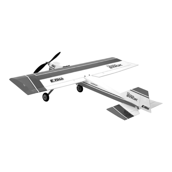
2100mAh 3-Cell 11.1V Li-Po, 16GA Thank you for purchasing the E-flite Mini Ultra Stick PNP ™ ™ The Mini Ultra Stick PNP is an electric park flyer version of EFLB1035 11.1V 2100mAh 3-Cell Li-Po, 16GA the popular Hangar 9 ®... - Page 6 Optional Accessories Before Starting Assembly EFLA110 Power Meter Before beginning final assembly of your Mini Ultra Stick PNP, EFLP1080E 10x8 Electric Prop remove each part from its bag for inspection. Closely inspect the fuselage, wing panels, rudder and stabilizer for damage.
-
Page 7: Note On Lithium Polymer Batteries
Limited Warranty Period Note on Lithium Polymer Batteries Horizon Hobby, Inc. guarantees this product to be free Lithium Polymer batteries are significantly from defects in both material and workmanship at the more volatile than alkaline or Ni-Cd/ date of purchase. Ni-MH batteries used in RC applications. -
Page 8: Limited Warranty & Limits Of Liability
Limited Warranty & Limits of Liability Pursuant to this Limited Warranty, Horizon Hobby, Inc. will, REPAIR OR REPLACEMENT AS PROVIDED UNDER at its option, (i) repair or (ii) replace, any product determined THIS WARRANTY IS THE EXCLUSIVE REMEDY OF THE by Horizon Hobby, Inc. -
Page 9: Questions, Assistance, And Repairs
Inspection or Repairs Questions, Assistance, and Repairs If your product needs to be inspected or repaired, please Your local hobby store and/or place of purchase cannot call for a Return Merchandise Authorization (RMA). Pack provide warranty support or repair. Once assembly, setup the product securely using a shipping carton. -
Page 10: Non-Warranty Repairs
Non-Warranty Repairs Should your repair not be covered by warranty and the expense exceeds 50% of the retail purchase cost, you will be provided with an estimate advising you of your options. You will be billed for any return freight for non-warranty repairs. -
Page 11: Landing Gear Installation
Landing Gear Installation 1. Locate the landing gear assembly. Attach the landing gear assembly to the fuselage using Required Parts two 4-40 x 1/2" socket head screws and two • Fuselage #4 washers. • Landing gear assembly with wheels •... -
Page 12: Installing The Propeller
Installing the Propeller Note: It is very important that you check to be sure the propeller is balanced before installing Required Parts onto the shaft. An unbalanced propeller will • Fuselage w/motor cause performance issues. Some propellers will • Prop adapter need the center hole drilled out to fit the shaft size of your outrunner. -
Page 13: Tail Installation
Tail Installation 2. Attach the stabilizer using two 3mm washers and two 3mm locknuts. Do not tighten the locknuts all Required Parts the way until after the wing is installed and you • Fuselage check the alignment. • Rudder/Fin •... -
Page 14: Wing Preparation
Wing Preparation 1. Detach the servo arm from the servo by loosening the servo screw. Temporarily plug the Y-harness Required Parts connecting the two servos into the receiver With • Fuselage the radio on, center the servo. Re-install the •... -
Page 15: Quad Flap Modification (Optional)
First, you will need at least a 7-channel or greater transmitter • Thin CA and receiver with servo reversing capability. Each servo The Mini Ultra Stick PNP wing is designed with optional should be connected separately to the 7-channel receiver. quad-flaps. The ailerons have been designed with the option This will mean you should use two 12-inch servo extensions of cutting in half using a hobby knife. -
Page 16: Radio Installation
Radio Installation Required Parts • Fuselage • Receiver • Hook and loop material • Micro pushrod keeper (2) Required Tools and Adhesives • Screwdriver, #0 Phillips • Wire cutters 1. Plug in the servos and ESC into the receiver. Note: See our Mini Ultra Stick website page for radio tips for quad flap operation Mount the receiver to the side of the fuselage... - Page 17 2. Install the pushrod into the elevator control horn. Secure the pushrod wire using a micro pushrod wire keeper. Note: Do not cut the antenna wire, as this will reduce the range of your radio system.
-
Page 18: Final Assembly
Final Assembly 3. Detach the servo arm from the servo. With the radio on, center the servo first. Install the elevator Required Parts servo arm onto the servo and secure with servo • Fuselage w/motor and ESC screw. Physically center the elevator so it is in line •... - Page 19 4. With the aircraft fully assembled, install the battery into the battery compartment. Secure the ™ We have included our E-flite EC3 battery connector for battery using the hook and loop tape and a hook your convenience. This will allow your battery to connect and loop strap.
- Page 20 6. Connect the ESC to the motor. 5. Install the battery hatch to the top of the fuselage. The magnet will hold the battery hatch in place. Note: Now would be a good time to check the operation of the motor. It should rotate Important Information About Your Brushless ESC counter-clockwise when viewed from the front Make sure your ESC brake is programmed...
- Page 21 7. Plug in the aileron (and flap) servo leads. Slide 8 Check your alignment of the wing to the the wing dowels into the holes at the front. Use horizontal stabilizer at this time. You should the two 4-40 x 3/4" socket head screws and two have some play in the stab holes.
-
Page 22: Center Of Gravity
1. Turn on the transmitter and receiver of your The recommended Center of Gravity (CG) location for Mini Ultra Stick PNP. Check the movement of the Mini Ultra Stick PNP is 2 " (63mm) behind the the rudder, elevator and ailerons using the leading edge of the upper wing against the fuselage. -
Page 23: Range Testing The Radio
Range Testing the Radio Low Rate High Rate Ailerons: Up/Down " (15mm) 5/8" (19mm) 1. Before each flying session, be sure to Elevator: range check your radio. This is accomplished Up/Down 9/16" (18mm) 7/8" (23mm) by turning on your transmitter with the antenna collapsed. -
Page 24: Preflight
Preflight Note: Keep loose items that can get entangled in the propeller away from the prop. These include loose clothing, or other objects such as Check Your Radio pencils and screwdrivers. Especially keep your Before going to the field, be sure that your batteries are hands away from the propeller. -
Page 26: 2006 Official Ama National Model Aircraft Safety Code
2006 Official AMA National Model Aircraft Safety Code GENERAL 5) I will not fly my model unless it is identified with my name and address or AMA number on or in the 1) I will not fly my model aircraft in sanctioned events, model. - Page 27 2006 Official AMA National Model Aircraft Safety Code 3) At all flying sites a straight or curved line(s) must Documents of agreement and reports may exist be established in front of which all flying takes place between (1) two or more AMA Chartered Clubs, with the other side for spectators.
- Page 28 © 2006 Horizon Hobby, Inc. 4105 Fieldstone Road Champaign, Illinois 61822 (877) 504-0233 horizonhobby.com E-fliteRC.com 8894...