
Related Manuals for Hyundai DHY6000LE


Summary of Contents for Hyundai DHY6000LE
- Page 1 DIESEL GENERATOR SERVICE MANUAL OPEN TYPE: DHY6000LE / DHY6000LE-3 SOUNDPROOF TYPE: DHY6000SE / DHY6000SE-3 Licensed by Hyundai Corporation, Seoul, South Korea...
- Page 2 POWER PRODUCTS This manual contains information how to maintain and how to do troubleshooting. Keep this owner’s manual handy, so you can refer to it at any time. This service manual describes correct method of the maintaining this equipment. As a result of this disregard of our rules caused by person casualty and equipment damaged, our company does not assume any responsibility.
-
Page 3: Table Of Contents
CONTENTS POWER PRODUCTS PREFACE 1-1 Generator Component Identification 1-2 Control Panel 1-3 Specifications of generator 1-4 Specifications of engine 1-5 Maintenance Standard Periodic Maintenance 2.1 Service Intervals 2.2 Routine Maintenance Procedures Engine Disassembly and Reassembly 3.1 Disassembly 3.2 Reassembly 3.3 Recoil Starter Assembly Inspection and Service 4.1 Cylinder Head 4.2 Piston and Piston Pin... -
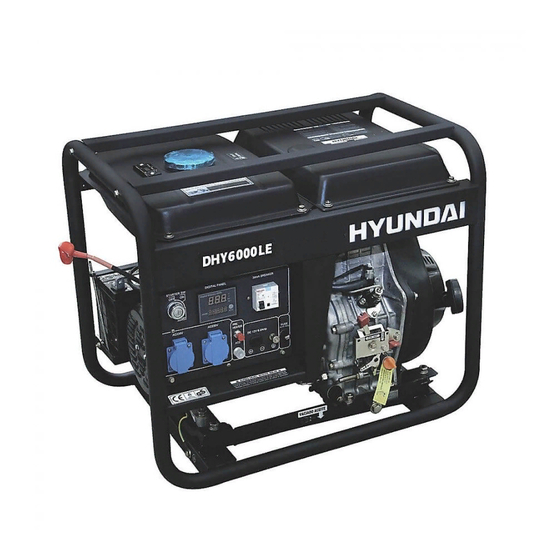
Page 4: Preface
POWER PRODUCTS 1. PREFACE 1-1 Generator Component Identification Open Type: DHY6000LE, DHY6000LE-3 FUEL TANK CAP UP COVER FRAME FUEL TANK DIESEL ENGINE CONTROL PANEL INJECTION PUMP RECOIL STARTER SPEED GOVERNOR ALTERNATOR COCK OF OIL DRANING RUBBER ABSORBER OIL PUMP BOTTOM FRAME... - Page 5 POWER PRODUCTS Soundproof Type: DHY6000SE, DHY6000SE-3 FUEL TANK CAP HOOK CONTROL PANEL AC OUTPUT SOCKET FRONT DOOR PUSH WHEELS FUEL LEVEL INDICATOR MUFFLER Changzhou ITC Power Equipment Manufacturing Co.,Ltd. Changzhou ITC Power Equipment Manufacturing Co.,Ltd.
-
Page 6: Control Panel
POWER PRODUCTS 1-2 CONTROL PANEL OPEN TYPE: DHY6000LE ELECTRIC START KEY LED4 DISPLAY LEAKAGE BREAKER PRE-HEATER BUTTON 12V DC FUSE GROUND TERMINAL SOCKET ATS SIGNAL SOCKET 12V DC SOCKET SUNDPROOF TYPE: DHY6000SE ELECTRIC START KEY LEAKAGE BREAKER E-STOP BUTTON LED4 DISPLAY... -
Page 7: Specifications Of Generator
POWER PRODUCTS 1-3 Specifications of generator open type DHY6000LE-3 Generator Model DHY6000LE Frequency 50 / 60 50 / 60 Rated power 4.5 / 5.0 5.6 / 6.3 4.5 / 5.0 4.5 / 5.0 Max. power 5.0 / 5.5 6.2 / 6.9... - Page 8 POWER PRODUCTS soundproof type Generator Model DHY6000SE DHY6000SE-3 Frequency 50 / 60 50 / 60 Rated power 4.5 / 5.0 5.6 / 6.3 4.5 / 5.0 4.5 / 5.0 Max. power 5.0 / 5.5 6.2 / 6.9 Voltage 230 / 240 400 / 420 Rated current 19.6 / 20.8...
-
Page 9: Specifications Of Engine
POWER PRODUCTS 1-4 Specificat ions of engine D400 D400 7.3kW(10.0hp) Air cooled diesel engine Performance Performance Curves Curves Kmg Nm °C PS kW D400/E Diesel Engine Model g/kWh g/PSh Single cylinder, vertical, 4-stroke, air-cooled Type 86x72 (3.39x2.83) BoreXstroke [mm(in)] 0.418 (418) Displacement [L(cc)] 1000 1200 1400 1600 1800 2000 2200 2400 2600 2800 3000 3200 3400 3600 3800 4000 19:1... -
Page 10: Maintenance Standard
POWER PRODUCTS 1-5 Maintenance Standard Diesel Engine Parts Item Standard Service limit Maximum Speed (No Load) 3150~3180rpm Diesel ≥1.17Mpa(1400rpm) Engine Cylinder Compression +0.035 Cylinder Sleeve I.D 86.185mm 86.0mm Cylinder Head Warpage 0.10mm Cover Skirt O.D. 85.94mm 85.80mm Piston-to-Cylinder Clearance 0.015-0.05mm 0.12mm -.0002 Piston... - Page 11 POWER PRODUCTS Cam Height 27.7mm 27.45mm Camshaft Cam Height 27.75mm 27.50mm Journal O.D 13.984mm 13.916mm Crankcase Camshaft Bracket I.D 14.0mm 14.048mm Cover Main Jet Carburetor Float Height 13.7±1.5mm Pilot Screw Opening 2-1/8 turns Spark Plug 0.7-0.8mm Spark Plug Resistance 5kΩ Resistance Primary Coil 0.8-1.0Ω...
-
Page 12: Periodic Maintenance
POWER PRODUCTS 2. Periodic Maintenance 2.1 Service Intervals Good maintenance is essential for safe, economical, and trouble-free operation. It will also help reduce air pollution. Exhaust gas contains poisonous carbon monoxide. Shut off the engine before WARNING perform any maintenance. If the engine must be run, make sure the area is well ventilated. -
Page 13: Routine Maintenance Procedures
POWER PRODUCTS 2-2 Routine Maintenance Procedures 2.2.1 Oil Change Drain the used oil while the engine is warm. Warm oil drains quickly and completely. 1. Place a suitable container below the engine to catch the used oil, and then remove the filler cap/dipstick and the drain plug. - Page 14 POWER PRODUCTS 2.2.3 Air Filter Service Remove the air cleaner cover and inspect the filter. Clean or replace dirty filter elements. Always replace damaged filter elements. 2.2.4 Fuel Filter Service 1. Drain out the fuel from the fuel tank. Turn the screw in the drain plug counter clockwise until fuel flows.
- Page 15 POWER PRODUCTS 2.2.5 Adjust the valve clearance (1) The clearance must be adjusted when the engine is cold. (2) Valve timing ° 4 Intake Close 50°after BDC ° 4 Exhaust Close 10°after TDC Changzhou ITC Power Equipment Manufacturing Co.,Ltd. Changzhou ITC Power Equipment Manufacturing Co.,Ltd. Changzhou ITC Power Equipment Manufacturing Co.,Ltd.
-
Page 16: Engine Disassembly And Reassembly
POWER PRODUCTS 3. Engine disassembly and reassembly 3.1 Disassembly 3.1.1 Fuel tank 1. Release the joint between the fuel line and fuel tank. 2. Release the hose clamp of the fuel line on the pump side. 3. Remove the tank. 3.1.2 Exhaust Muffler 1. - Page 17 POWER PRODUCTS 3.1.7 Air inlet pipe 3.1.8 Remove electric starter motor 3.1.9 Remove cylinder head cover 3.1.10 Valve rocker arm seat 3.1.11 Push rods 3.1.12 Fuel injector (1) Remove the high-pressure fuel line. (2) Remove fuel injector. (3) Be careful not to damage the nozzle washer and spacer. Changzhou ITC Power Equipment Manufacturing Co.,Ltd.
- Page 18 POWER PRODUCTS 3.1.7 Air inlet pipe 3.1.8 Remove electric starter motor 3.1.9 Remove cylinder head cover 3.1.10 Valve rocker arm seat 3.1.11 Push rods 3.1.12 Fuel injector (1) Remove the high-pressure fuel line. (2) Remove fuel injector. (3) Be careful not to damage the nozzle washer and spacer. Changzhou ITC Power Equipment Manufacturing Co.,Ltd.
- Page 19 POWER PRODUCTS 3.1.13 Remove the cylinder head 3.1.14 Remove the injection pump (1) Remove the pump together with the base. (2) Ensure the hooking part of control lever is at the meshing position before disassembling. (3) Pull out the flat tappet remaining inside the housing 3.1.15 Crankcase cover (1) Remove the engine oil injection pump cover.
- Page 20 POWER PRODUCTS (1) Remove the camshaft taking care not to damage the oil seal. (2) Note the position of the timing mark (3) Remove and store the intake and exhaust tappets separately. 3.1.17 Remove balance shaft 3.1.18 Piston and connecting rod assembly (1) Dismount the forcing nut of connecting rod.
- Page 21 POWER PRODUCTS 3.1.19 Flywheel (1) Loosen the flywheel nut. (2) Remove the flywheel. ·Use flywheel extractor ·Securely thread in the extractor bolts. 3.1.20 Crankshaft (1) Remove the flywheel key (2) Remove the main bearing thrust plate (3) Pull out the crankshaft taking care not to damage the oil seal.
-
Page 22: Reassembly
POWER PRODUCTS 3.2 Reassembly Reassembly procedures ·Thoroughly check and clean all parts. ·Apply fresh engine oil or assembly lube to all moving and rotating parts. ·Use new O rings and gaskets. ·Apply liquid sealant when no gasket is specified ·Be sure all clearances and specifications among parts are observed. ·Align matching marks while reassembling. - Page 23 POWER PRODUCTS Connecting Rod Nut Torque Value 38-42 N.m 3.2. 5 Camshaft and balance shaft (1) Insert the tappets. (2) Insert the cam shaft. (3) Insert the balance shaft. ·Do not confuse the intake and exhaust tappets. ·Check whether the matching marks of gear are aligned correctly. 3.2.6 Crankcase cover (1) Place an aluminum washer between the surface of crankcase and the cover.
- Page 24 POWER PRODUCTS Crankcase Cover Bolt and Stiffener Bolt Torque Value 20-23 N.m (3). Add the stiffener bolts to the crankcase cover for reducing vibration and noise, which should be tightened after other bolts around crankcase cover tightened. 3.2.7 Reassemble the fuel injection pump (preliminary assembly) (1) Align with the oil level marks on the injection pump (2) Insert the governor lever into the fork groove of the governor.
- Page 25 POWER PRODUCTS Tightening torque of cylinder head bolts n i l t i n l a i 30 N.m 3.2.10 Push rod Insert the push rod and check whether it is in proper position. 3.2.11 Rocker arm assembly (1). Reassemble the rocker arm assembly. (2).
- Page 26 POWER PRODUCTS 3.2.12 Cylinder head cover Install with a new gasket 3.2.13 Fuel injector (1) Install the fuel injector assembly. (2) Tighten the lock bolts. (3) Install the high-pressure fuel line. ·Be sure the installation direction of fuel injector is correct. ·Replace the nozzle washer when reassembling.
- Page 27 POWER PRODUCTS 3.2.16 Air cleaner (1) Install the air cleaner bottom case. (2) Install the element. (3) Install the air cleaner cover. ·Check whether the inlet pipe and gaskets are in the proper position. 3.2.17 Starting motor Install the electric starting motor. 3.2.18 Exhaust muffler Install the exhaust muffler.
-
Page 28: Recoil Starter Assembly
POWER PRODUCTS 3.3 Recoil starter assembly 3.3.1 Disassembly (1) Remove the recoil starter assembly from the engine. Note the direction of rotation. (2) Pull the rope out about 12 inches or 30 cm. When the gap of starter reel attaches the end of the starter rope, stop the reel with your finger and pull the rope out with an awl as show below in figure (a). - Page 29 POWER PRODUCTS (2) Wind the starter rope around the reel as per figure (g). Take the rope from the gap after two ½ revolutions and engage the spring’s inner end with the reel’s hook. Place the reel into the case. (3) Hold the starter rope as shown in figure (h).
- Page 30 POWER PRODUCTS 3.3.3 Inspection after reassembling (1) Pull out the starter rope three times. - Pull the rope slowly to check whether the parts are in proper position. - If the ratchet wheel does not move check whether the spring is in proper position.
-
Page 31: Inspection And Service
POWER PRODUCTS 4. INSPECTION AND MAINTENANCE 4.1 Cylinder head 4.1.1 Combustion chamber surface Disassemble the fuel injection valve, the intake valve and exhaust valve. Clean the combustion chamber surface and check for cracks and other damage. 4.1.2 Inlet and exhaust valve seats Freeze the valve seat with liquid nitrogen for improving durability, then insert it into the cylinder head. - Page 32 POWER PRODUCTS 4.1.5 Measure the top clearance of the piston (1) Remove the cylinder head and then place threeφ1.2 x 10mm fuses of the same length at three points on the upper limit level of the piston. (2) Reassemble the cylinder head and the gaskets then tighten the nuts at the specified tightening torque and specified order.
-
Page 33: Piston And Piston Pin
POWER PRODUCTS Outer diameter of the inlet/exhaust valve rocker arm 14.989-15.000 mm 14.94 mm pivot Inner diameter of the inlet/exhaust valve rocker arm . 15.016-15.034 mm 15.10 mm hole 4.1.7 Adjust the valve clearance (1) The clearance must be adjusted when the engine is cold. (2) Valve timing °... - Page 34 POWER PRODUCTS 4.2.2 Piston and Piston pin (1) Measure the piston pin outer diameter, if it worn out beyond the maintenance limit or already distorted into ladder shape, it should be replaced. Outer diameter of the piston 22.991-23.000 mm 22.91 mm 4.2.3 Piston Bore (1) If the bore is warped, elongated or otherwise damaged, it must be replaced.
-
Page 35: Connecting Rod
POWER PRODUCTS 4.2.4 Piston ring (1) Assemble and disassemble the piston ring with a piston ring compressor. (2) Face the section with the marks upward while assembling the piston ring. (3) Be sure that piston ring rotates smoothly after installation. (4) When inserting the helical elastic collar into the oil ring, be sure the joint of the helical elastic is at the opposite of the opening of oil ring. -
Page 36: Crankshaft, Main Bearing And Flywheel
POWER PRODUCTS 4.4 Crankshaft, main bearing and flywheel 4.4.1 Crankshaft (1). Coating check crank journals. - clean the crankshaft then check for cracks by magnafluxing. Replace if any cracks are discovered. (2). Measure the crank pin and the main journal Check the condition of the crank pin and the main journal. -
Page 37: Camshaft
POWER PRODUCTS 4.5 Camshaft 4.5.1 Camshaft (1) Check the thrust clearance of the camshaft (cylinder block side). The crankshaft bearing has been pressed into the cylinder block. Maintain the sinking clearance between the end face of the pressed bearing and the thrust surface of the cylinder body at 1.4-1.5mm. 4.5.2 Tappet (1) Check the condition of the tappet contacts. -
Page 38: Crankshaft Cover
POWER PRODUCTS 4.7 Crankcase cover Be careful of the aluminum gasket while disassembling, replace it if it damaged or distorted. Furthermore, be sure to tighten the crankcase cover bolts with the specified tightening torque below. Crankcase cover bolt tightening 20-23 N.m torque 4.7.1 Cleaning and inspection Rinse the cylinder block before reassembly. -
Page 39: Cylinder Sleeve And Block
POWER PRODUCTS LO flow path LO flow path LO filter LO pump Main bearing/Crank neck journal Intake pipe LO filter LO pump Connecting rod shaft journal Main bearing Crank neck journal Connecting rod shaft journal 4.7.2 Replace the crankshaft oil seal and the camshaft oil seal Replace the oil seal with a seal installation tool. - Page 40 POWER PRODUCTS 4.9.1 Lube oil pump (1). Measure the clearance between the outer rotator of the lube oil pump and the lube oil pump body on the crankcase cover. Replace the lube oil pump if the clearance exceeds the permitted limit. (2).
-
Page 41: Fuel System
POWER PRODUCTS 4.10 Fuel System 4.10.1 Fuel injection pump 4.10.2 Fuel injection valve (1) Clean the nozzle orifice when disassemble the fuel injection valve, what more, do not place the injection nozzle on the dirty ground. (2) Inspection: ① Carbon deposit (Flowering) The carbon on the injection nozzle will seriously reduce the combustion efficiency so avoid any pollution of the injection nozzle. -
Page 42: Governor
POWER PRODUCTS (5) Disassembly and reassembly Disassemble the fuel injection valve lock nut with a 15mm box wrench. (6) Adjustment The nominal fuel pressure is 2840 psi or 200kg/cm , but the fuel spraying pressure can be adjusted by adding or reducing spacer shims. The fuel spraying pressure will change 28.4 psi or 20kg/cm when adding or removing one 0.1mm shim. -
Page 43: Adjustments
POWER PRODUCTS 4.12 Adjustments 4.12.1 Fuel injection timing (1) Checking fuel injection timing: - Set the governor lever on “RUN” position. - Disassemble the high-pressure fuel line and install a line used for testing the fuel injection timing. - Turn the flywheel till the upper limit mark is aligned with the “V” scale mark on the radiating fin of the cylinder. - Page 44 POWER PRODUCTS (4) Remove the fitting that connects the fuel line from the injection pump to the injector. Pull the recoil starter or engage the electric starter until the fuel flow is steady. Retorque the fuel line. Repeat this step until the unit starts and runs. Be sure to contain any diesel fuel that spills as a result of this process.
-
Page 45: Troubleshooting
POWER PRODUCTS 5. TROUBLESHOOTING 5.1 No fuel delivery to injection pump a. Check there is sufficient fuel in the tank and the fuel valve is in the open position b. Ensure the governor lever is in the “Run” Position c. Check that the fuel filter is not clogged. d. -
Page 46: No Start Or Hard Start (Engine Cranks)
POWER PRODUCTS 5.5 No start or hard starting (engine cranks) Cause and remedy Main cause Remedy Special explanation Improper fuel (1) Poor quality fuel or wrong (1) Use the specified diesel (1).Use the recommend fuel blend (2) There’s water in the diesel (2) Replace the fuel (2) Follow the proper transport, storage and water... -
Page 47: Engine Over Speed
POWER PRODUCTS 5.6 Engine over speed If the engine over speeds while starting or operating, stop the engine immediately with the governor handle or decompression lever. A malfunction of the governing system will cause over speeding. Possible cause: Cause and remedy Main cause Remedy Special explanation... -
Page 48: Generator
POWER PRODUCTS Changzhou ITC Power Equipment Manufacturing Co.,Ltd. Changzhou ITC Power Equipment Manufacturing Co.,Ltd. Changzhou ITC Power Equipment Manufacturing Co.,Ltd. Changzhou ITC Power Equipment Manufacturing Co.,Ltd. Changzhou ITC Power Equipment Manufacturing Co.,Ltd. - Page 49 POWER PRODUCTS BLACK YELLOW GREEN BLACK GREEN Changzhou ITC Power Equipment Manufacturing Co.,Ltd. Changzhou ITC Power Equipment Manufacturing Co.,Ltd. Changzhou ITC Power Equipment Manufacturing Co.,Ltd. Changzhou ITC Power Equipment Manufacturing Co.,Ltd. Changzhou ITC Power Equipment Manufacturing Co.,Ltd.
- Page 50 POWER PRODUCTS Changzhou ITC Power Equipment Manufacturing Co.,Ltd. Changzhou ITC Power Equipment Manufacturing Co.,Ltd. Changzhou ITC Power Equipment Manufacturing Co.,Ltd. Changzhou ITC Power Equipment Manufacturing Co.,Ltd. Changzhou ITC Power Equipment Manufacturing Co.,Ltd.
- Page 51 POWER PRODUCTS BLACK D400 Changzhou ITC Power Equipment Manufacturing Co.,Ltd. Changzhou ITC Power Equipment Manufacturing Co.,Ltd. Changzhou ITC Power Equipment Manufacturing Co.,Ltd. Changzhou ITC Power Equipment Manufacturing Co.,Ltd. Changzhou ITC Power Equipment Manufacturing Co.,Ltd.
- Page 52 POWER PRODUCTS BLACK BLACK D400 Changzhou ITC Power Equipment Manufacturing Co.,Ltd. Changzhou ITC Power Equipment Manufacturing Co.,Ltd. Changzhou ITC Power Equipment Manufacturing Co.,Ltd. Changzhou ITC Power Equipment Manufacturing Co.,Ltd. Changzhou ITC Power Equipment Manufacturing Co.,Ltd.
- Page 53 POWER PRODUCTS Changzhou ITC Power Equipment Manufacturing Co.,Ltd. Changzhou ITC Power Equipment Manufacturing Co.,Ltd. Changzhou ITC Power Equipment Manufacturing Co.,Ltd. Changzhou ITC Power Equipment Manufacturing Co.,Ltd. Changzhou ITC Power Equipment Manufacturing Co.,Ltd.
-
Page 54: Circuit Diagram
POWER PRODUCTS 7 Circuit Diagram Open type: DHY6000LE Changzhou ITC Power Equipment Manufacturing Co.,Ltd. Changzhou ITC Power Equipment Manufacturing Co.,Ltd. Changzhou ITC Power Equipment Manufacturing Co.,Ltd. Changzhou ITC Power Equipment Manufacturing Co.,Ltd. Changzhou ITC Power Equipment Manufacturing Co.,Ltd. - Page 55 POWER PRODUCTS Open type: DHY6000SE Changzhou ITC Power Equipment Manufacturing Co.,Ltd. Changzhou ITC Power Equipment Manufacturing Co.,Ltd. Changzhou ITC Power Equipment Manufacturing Co.,Ltd. Changzhou ITC Power Equipment Manufacturing Co.,Ltd. Changzhou ITC Power Equipment Manufacturing Co.,Ltd.
-
Page 56: Appendix
POWER PRODUCTS Changzhou ITC Power Equipment Manufacturing Co.,Ltd. Changzhou ITC Power Equipment Manufacturing Co.,Ltd. Changzhou ITC Power Equipment Manufacturing Co.,Ltd. Changzhou ITC Power Equipment Manufacturing Co.,Ltd. Changzhou ITC Power Equipment Manufacturing Co.,Ltd. - Page 57 POWER PRODUCTS Changzhou ITC Power Equipment Manufacturing Co.,Ltd. Changzhou ITC Power Equipment Manufacturing Co.,Ltd. Changzhou ITC Power Equipment Manufacturing Co.,Ltd. Changzhou ITC Power Equipment Manufacturing Co.,Ltd. Changzhou ITC Power Equipment Manufacturing Co.,Ltd.