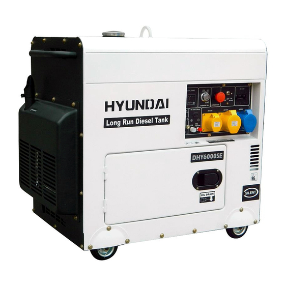
Hyundai DHY6000SE User Manual
Diesel generator - 3000rpm
Hide thumbs
Also See for DHY6000SE:
- User manual (32 pages) ,
- Service manual (57 pages) ,
- User manual (19 pages)
Table of Contents
Advertisement
Advertisement
Table of Contents

Related Manuals for Hyundai DHY6000SE


Summary of Contents for Hyundai DHY6000SE
- Page 1 DIESEL GENERATOR - 3000rpm Models DHY6000SE/LR -- - DHY8000SE/LR User Manual...
-
Page 2: Table Of Contents
CONTENTS Section Description Page N o’s 1. SAFETY 3 - 7 2. MACHINE LAYOUT 7 - 8 3. PREPARATION for STARTING 8 - 11 4. OPERATING THE GENERATOR 12 - 14 5. LOAD 14 - 15 6. STOPPING THE MACHINE 7. -
Page 3: Safety
1. SAFETY. 1.1. The operator of the machine is; 1.1.1. Responsible for and has a duty of care in making sure that the machine is operated safely and in accordance with the instructions in this user manual. 1.1.2. Should never be left it in a condition which would allow an untrained or unauthorised person/s to operate this machine. - Page 4 1.3. Carbon Monoxide 1.3.1. Carbon monoxide is a colourless and odourless gas. Breathing in this gas can cause death as well as serious long term health problems such as brain damage. 1.3.2. The symptoms of carbon monoxide poisoning can include the following; 1.3.2.1.
- Page 5 1.4.7. Dispose of waste fuels correctly. 1.4.8. Diesel safety. 1.4.8.1. Always fuel and defuel in well-ventilated area. 1.4.8.2. Always wear correct, suitable and fit for purpose Personal Protective Equipment (PPE), suggested items are as follows, but are not limited too. 1.4.8.3.
- Page 6 1.4.10.5. Never work on or near electricity with wet hands, wet clothing, and wet gloves. 1.4.10.6. Batteries present a risk if they become damage by the possible leaking of electrolyte. This electrolyte is an acid and can cause serious injuries. Care should be taken when working on or near them. 1.4.10.6.1.
-
Page 7: Machine Layout
1.5.4. AC Switch (Breaker) 1.5.4.1. The AC Switch (Breaker) will turn ‘OFF’ automatically when the load exceeds the generator output. 1.5.4.2. If AC switch turns ‘OFF’ then before resetting remove some of the load and keep below the rated output of the machine. 1.5.5. -
Page 8: Preparation For Starting
3. PREPARATION for STARTING • DO NOT refill tank while engine is running or HOT. • Do not smoke or allow flames or sparks in the area where the engine is refueled or where the fuel is stored. • Do not overfill the diesel tank and make sure the filler cap is securely closed after refueling. - Page 9 • If an insufficient amount of engine oil is used, damage to the engine may result. • Do not overfill the engine with oil. • This generator is equipped with a low oil pressure switch this system will stop the engine automatically when the oil pressure falls below the minimum pressure required.
- Page 10 3.3.1. Remove the access panel to reveal air filter cover. 3.3.2. Undo the nut (anti- clockwise) and remove the air cleaner cover and take out the element. 3.3.3. Clean the air filter. 3.3.4. Reattach the air filter cover and screw on the nut.
- Page 11 3.6. Battery. • Do not connect tools or any other appliances to the generator before starting. • Explosive gases are given off when charging battery. Only charge in a well-ventilated area, away from sparks and naked flames. 3.6.1. Battery. 3.6.1.1. When you first install the battery, ensure that the battery's polarity is the same as the generator's battery leads - Black = negative, Red = positive.
-
Page 12: Operating The Generator
4. OPERATING THE GENERATOR • Do not loosen or readjust either the engine speed limiting bolt or the fuel injection limiting bolt as this will cause the performance of the generator to be affected. 4.1. Starting. 4.1.1. Turn the main AC switch to the 'OFF' position. 4.1.2. - Page 13 4.1.9. Always leave the key in the ‘ON’ position whilst the engine is running. 4.1.10. Run machine for two minutes before applying load 4.1.11. Insert the plug into the socket you are about to use. 4.1.12. Turn the main AC switch to the 'ON' position and turn the electrical appliance ‘ON’. •...
-
Page 14: Load
4.2.8. The following are possible causes for a NO start, 4.2.8.1. STOP/START lever in STOP position. 4.2.8.2. Emergency STOP button activated. 4.2.8.3. Low or no fuel. 4.2.8.4. Flat battery. 4.3. Checks whilst generator is running. 4.3.1. After each use make sure that there are no abnormal sounds or vibration. 4.3.2. -
Page 15: Stopping The Machine
5.1.6. To reset the breaker do the following; 5.1.6.1. Turn OFF and disconnect all loads. 5.1.6.2. Reset breaker, and add load onto the circuit to within 50% to 75% of rated output. 5.1.7. Wait a few minutes before resuming operation. 5.2. -
Page 16: Periodic Maintenance
7. PERIODIC MAINTENANCE • Ensure the engine is off before performing any service. • If the engine must be run, make sure that the area is well ventilated. • The exhaust contains poisonous carbon monoxide gas. 7.1. Maintenance chart. All work/s should be carried out by a competent person – if you need technical advice contact Genpower First Every Every... -
Page 17: Long Term Storage
8. LONG TERM STORAGE • After running the engine the oil will be very hot. • Wear correct PPE minimum of gloves and overalls. 8.1. If storing the generator for long periods of time, make the following operations. 8.1.1. Operate the engine for 10 minutes and then stop. 8.1.2. -
Page 18: Troubleshooting
9. TROUBLESHOOTING. 9.1. Troubleshooting - N.B. all corrective actions should be carried out by suitably qualified person/s. Problem Possible fault/cause Remedy The governer lever is not at Set lever to START position START position Emergency STOP button Re-set emergency STOP activated (depressed) button Insufficient fuel... -
Page 19: Specifications
Fuel Tank capacity (Litres) DC Output Volts - 12V 8.3A Amps Battery 12 v 36Ah Engine Type Diesel Hyundai D400, Forced Air- Hyundai D500, Forced Air- Engine cooled, OHV cooled, OHV Power Output HP 10 HP 12 HP Start method... -
Page 20: Wiring Diagram
11. WIRING DIAGRAM 11.1. (N.B. Subject to change without prior notice). Page 20 Rev 2... -
Page 21: Service Record Sheet
12. SERVICE RECORD SHEET Date Hours Maintenance undertaken Name Page 21 Rev 2... -
Page 22: Genpower Contact Details
13. GENPOWER CONTACT DETAILS 13.1. Postal address; Genpower Limited, Isaac Way, Pembroke Dock, Pembrokeshire, SA72 4RW, UK. 13.2. Telephone and Fax contact numbers; Office +44 (0) 1646 687880 13.3. Email contact; Technical service@genpower.co.uk 13.4. Web site; www.hyundaipowerequipment.co.uk Page 22 Rev 2... -
Page 23: Declarations Of Conformity
14. DECLARATIONS OF CONFORMITY 14.1. Genpower Ltd confirms that these Hyundai products conform to the following CE Directives; 14.1.1. 2006/42/EC Machinery Directive 14.1.2. 2004/108/EC EMC Directive 14.1.3. 2000/14/EC Noise Emissions Directive 14.1.4. 97/68/EC NRMM Emissions Directive 14.1.5. 2006/95/EC Low Voltage Directive... - Page 24 Isaac Way, London Road Pembroke Dock, UNITED KINGDOM, SA72 4RW T: +44 (0) 1646 687 880 F: +44 (0) 1646 686 198 E: info@hyundaipowerequipment.co.uk www.hyundaipowerequipment.co.uk...