
Related Manuals for Canon CR-1


Summary of Contents for Canon CR-1
- Page 1 Digital Retinal Camera CR-1 Operation Manual Before using the instrument, be sure to read this manual thoroughly. Keep the manual where it is easily accessible.
- Page 2 Be sure to avoid having objects such as these, which affect this product, brought near the product. 6. In no event will Canon be liable for direct or indirect consequential damage arising out of the use of this product. Canon will not be liable for loss of image data due to any reason.
- Page 3 This instrument conforms to IEC 60601-1-2:2001. For U.S.A. and Canada • When the CR-1 is going to be operated at a voltage of 240V in USA or Canada, be sure to connect the instrument to a center tapped voltage source.
-
Page 4: Guidance And Manufacturer's Declaration For Emc Directive
Guidance and Manufacturer’s Declaration for EMC Directive Electromagnetic Emissions The CR-1 is intended for use in the electromagnetic environment specified below. The user of the CR-1 should assure that it is used in such an environment. Emission Test Compliance Electromagnetic Environment – Guidance The CR-1 uses RF energy only for its internal function. -
Page 5: Electromagnetic Immunity
Safety Information Electromagnetic Immunity The CR-1 is intended for use in the electromagnetic environment specified below. The user of the CR-1 should assure that it is used in such an environment. IEC 60601 Test Compliance Electromagnetic Environment – Immunity Test... - Page 6 RF transmitters, an electromagnetic site survey should be considered. If the measured field strength in the location where the CR-1 is used exceeds the applicable RF compliance level above, the CR-1 should be observed to verify normal operation. If abnormal performance is observed, additional measures may be necessary, such as reorienting or relocating the CR-1.
- Page 7 Safety Information Recommended Separation Distances The CR-1 is intended for use in an electromagnetic environment in which radiated RF distur- bances are controlled. The user of the CR-1 can help prevent electromagnetic interference by maintaining a minimum distance between portable and mobile RF communications equipment (transmitters) and the CR-1 as recommended below, according to the maximum output power of the communications equipment.
-
Page 8: General Safety Information
Safety Information General Safety Information Follow the safety instructions in this manual and all warnings and cautions printed on the warning labels. Ignoring such cautions or warnings while handling the product may result in injury or accident. Be sure to read and fully understand the manual before using this product. Keep this manual for future reference. -
Page 9: Power Supply
Also, when other equipment is going to be connected to the instrument using WARNING the connector for interface, be sure to check after the connection that leakage current is within the tolerable value. For details, please contact a Canon rep- resentative or distributor. Power Supply... - Page 10 Safety Information Power Supply Be sure to hold the plug to disconnect the power cable. If you pull the cable, the core wire may be damaged, resulting in fire or electric WARNING shock. Do not cut or process the cables. Also, do not place anything heavy, including the instrument on it, step on it, pull it, bend it, or bundle it.
-
Page 11: Maintenance And Inspection
When Problem Occurs Should any of the following occur, immediately turn OFF the power of each instrument, unplug the power cable from the AC outlet, and contact a Canon representative or distributor. • When there is smoke, odd smell or abnormal sound. -
Page 12: Labels And Markings On The Instrument
Safety Information Labels and Markings on the Instrument The CR-1 has a label on it. The label contents and its position are indicated below. (10) -
Page 13: Table Of Contents
Contents Safety Information..................(1) Regulations ....................(1) Guidance and Manufacturer’s Declaration for EMC Directive ....(2) General Safety Information ..............(6) Labels and Markings on the Instrument ..........(10) 1. Features...................... 1 2. Notes for Using the Instrument ..............2 3. Description ....................4 3.1 Main Unit ................... 4 3.2 Operation Panel ................. - Page 14 Contents 6.6 Attaching and Removing the EOS Digital Camera ......33 6.6.1 Attaching the EOS Digital Camera ........33 6.6.2 Removing the EOS Digital Camera ........34 6.7 Connecting the USB Cable .............. 36 6.8 Carrying the Instrument ..............37 7.
-
Page 15: Safety Information
1. Features The Canon CR-1 digital retinal camera is used to take digital photographic retinal images of patient’s eyes across a wide range (photographic angle of view of 45 degrees) in a naturally dilated state without the use of mydriatics. It has the following features. -
Page 16: Notes For Using The Instrument
2. Notes for Using the Instrument Before Use • Check and clean the objective lens before taking an image, as any stains or scratches on it will appear as white spots. • Sudden heating of the room in cold areas will cause condensation to form on the objective lens or on optical parts inside the instrument. - Page 17 Federal law restricts this device to sale by or on the order of a licensed practitioner. Intended Use: CR-1 is intended to be used for taking digital images of retina of human eye without a mydriatic. For European Union Intended Use: This medical device is intended to observe image and record retinal fundus through the pupil without contact with subject’s eye for the purpose of diagnosis by way of producing fundus image information.
-
Page 18: Description
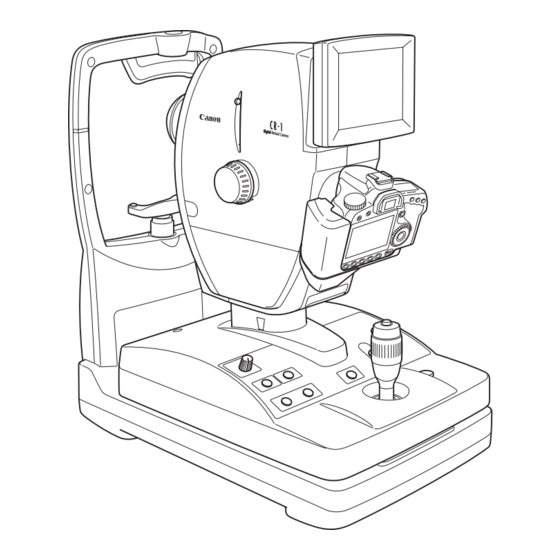
3. Description 3.1 Main Unit Symbol Name Function Diopter compensation Used when the target is not brought into focus by turning the lever focus knob. Adjust so that the height of the patient’s eye is aligned with this Height adjustment mark mark. - Page 19 3. Description Symbol Name Function External eye fixation unit Accepts the external eye fixation unit (sold separately). terminal Objective lens Lens used for photography. Stage unit lock button Locks and unlocks the stage unit. The power turns ON when pressed to the I side, and the power Power switch turns OFF when pressed to the O side.
-
Page 20: Operation Panel
3. Description 3.2 Operation Panel Symbol Name Function Brightness adjuster Used for adjusting brightness in field of view for observation. × Switches the ×2 photography function ON and OFF. 2 switch SP (Small pupil Switches the function for photographing small pupil diameters photography) switch ON and OFF. -
Page 21: Monitor Display Screens
3. Description 3.3 Monitor Display Screens STEREO STEREO Anterior eye observation screen Retina observation screen Symbol Name Function The photographic preparation status (see page 18) is indicated Photographic status by colors. × Appears when the ×2 photography function is ON. 2 photography Appears when the small pupil photography function is ON. - Page 22 3. Description...
-
Page 23: Operation
4. Operation Concerning the power-saving function The power-saving function is activated under the following circumstances. • When none of the switches on the operation panel has been operated, when the stage unit has not been switched to the left or right or when the diopter correction slider has not been operated for 10 or more minutes while power is supplied to the camera When the power-saving function has been activated, the POWER lamp on the operation panel blinks. - Page 24 4. Operation Unlock the stage unit. Press the stage unit lock button to release the lock. Adjust the height of the main unit. Turn the operation lever, and align the main unit with the center position of the height adjustment mark.
-
Page 25: Adjusting The Position And Focusing
4. Operation 4.2 Adjusting the Position and Focusing Have the patient sit down. Have the patient place his or her chin against the chin rest and his or her forehead against the forehead rest. Align the height of the patient’s eye. Move the chin rest up or down so that the patient’s eye is aligned with the height adjustment mark by operating the CHIN REST switches. - Page 26 4. Operation Align the position of the pupil. When adjusting the position of the main unit in the front-back direction, slowly bring the main unit closer to the patient while looking at the patient’s CAUTION eye from the side. You may injure the patient’s eye if the objective lens makes contact with it. Do not put your fingers or hands between the sliding part and base of the stage unit .
- Page 27 4. Operation Concerning the SP function Use the SP (small pupil photography) function if the pupil of the patient’s eye fails to become larger than the inside pupil position alignment mark even after waiting for a while in the darkened room.
- Page 28 4. Operation Display the retina observation screen. Press the ALIGNMENT switch. The internal eye fixation lamp flashes for 3 seconds. Note: When the stage unit is slid toward the other eye on the retina observation screen, the anterior eye observation screen is displayed. Concerning the stereo mode The stereo mode can be set to ON or OFF using the [Set menu] .Refer to 5.
- Page 29 4. Operation Decide on the area to be photographed. Have the patient stare at the green internal eye fixation lamp. If necessary, while viewing the monitor, press the FIX TARGET switch to move the internal eye fixation lamp, and guide the patient’s eye. The internal eye fixation lamp moves up and down and toward the left and right.
- Page 30 4. Operation Bring the eye into focus. Turn the focus knob and align the split lines into a single straight line. Split lines Working distance dots In the event of the following: When the split lines are not visible: If this is the case, refer to 6.2.1 Troubleshooting (see page 26). When the split lines are not aligned into a single straight line: If the split lines are not aligned: Use the diopter compensation lever to insert the diopter compensation lens, and take the...
- Page 31 4. Operation Note: When operating the diopter compensation lever, set it precisely to the 0, “–” or “+” position. If the lever is set to a position midway between two settings, fundus images will not be taken properly. Adjust the position of the retinal image. Tilt the operation lever forward or backward so that the left and right working distance dots are made as small as possible.
-
Page 32: Photography
4. Operation 4.3 Photography Take a photograph. Check that the photography status display is green. Shutter release In a flare-free status, check the focus again, and press button the shutter release button. A retinal image is now taken, and the anterior eye observation screen is displayed. However, the retina observation screen will remain on the monitor if the stereo mode is established. - Page 33 4. Operation Review the image. The fundus images and study information are displayed in the control software. Check the images. When the images taken are not clear If this is the case, refer to 6.2.1 Troubleshooting (see page 26). Now take a photography of the other eye. Taking photographs of one eye will cause the pupils of both eyes to contract excessively.
- Page 34 4. Operation -20-...
-
Page 35: Settings
5. Settings The various settings can be established on the setup menu screen. Display the setup menu screen. Press the SET switch on the anterior eye observation screen. The setup menu screen is now displayed. SET MENU >MONITOR PANEL ON . OFF STEREO ON . - Page 36 5. Settings Selection item Function Used to select whether to take photographs at low flash intensity levels. LOW FLASH ON: Photographs are taken at low flash intensity levels. OFF: Photographs are not taken at low flash intensity levels. Used to select whether to display the split lines for focusing. ON: The split lines are displayed.
-
Page 37: Daily Inspection And Maintenance
In order to ensure that the instrument is used safely and normally, please be sure to inspect the instrument before use. If the inspection finds a fault, and you are unable to correct the problem, please contact a Canon representative or distributor. - Page 38 6. Daily Inspection and Maintenance Result Inspection Month Month Month Remedy Check that the cover and parts Contact a Canon representative or Pass/ Pass/ Pass/ are not damaged and are not distributor if the cover and parts Fail Fail Fail loose.
-
Page 39: Turning On The Power
Turn on the power of all the equipment which has been connected as a system. Result Inspection Remedy Month Month Month Contact a Canon representative or Check whether the POWER Pass/ Pass/ Pass/ distributor if the power cable is lemp lights. -
Page 40: Before Calling A Service Technician
If performing the remedy still does not fix the problem, or the warning is still displayed, turn OFF the power, and contact a Canon representative or distributor. Please be sure to describe the problem or warning message in detail. - Page 41 Set to the no compensation position. set to the - side or + side. The LED used to display the split Contact a Canon representative or lines has been burnt out. distributor. Turn the focus knob to focus so that the The split lines do not The diopter of the patient’s eye is...
-
Page 42: What To Do When These Displays Appear
6. Daily Inspection and Maintenance 6.2.2 What to Do when These Displays Appear If a message fails to be cleared even after taking the remedial action suggested below, contact a Canon representative or distributor, and provide full details of the message which is displayed. -
Page 43: Cleaning And Disinfection
Note: Do not let the tip of a blower touch the objective lens. Use the procedure below to clean the objective lens when it is dirty. Please order the lens cleaning paper, lens cleaner, and blower from a Canon representative or distributor. Check for any dust or dirt. -
Page 44: Forehead Rest
6. Daily Inspection and Maintenance 6.3.2 Forehead Rest To prevent the risk of infection, wipe the forehead rest with disinfecting ethanol, glutaraldehyde solution, or other disinfectant whenever changing patients. CAUTION For more details on the disinfection procedure, please consult a specialist. Please also consult a specialist when using a disinfectant other than those specified above and then adding another disinfectant to ethanol since this could damage the forehead rest. -
Page 45: Refilling The Chin Rest Paper
6. Daily Inspection and Maintenance 6.4 Refilling the Chin Rest Paper Note: If the chin rest paper will not be used, be sure to disinfect the chin rest whenever the patient is changed in the same way as the forehead rest. Pull out the chin rest right and left holding pins. -
Page 46: Power Cable Connections
6. Daily Inspection and Maintenance 6.5 Power Cable Connections Be sure to operate this instrument using the power supply described in the WARNING specifications. Otherwise, it may result in fire or electric shock. Be sure to turn OFF the power before plugging or unplugging the cables as WARNING indicated in this manual. -
Page 47: Attaching And Removing The Eos Digital Camera
Mount the EOS digital camera to the main unit. Align the EF lens mount index of the EOS digital camera with the CR-1 positioning mark. Positioning mark EF lens mount index Fit the lens mount of the EOS digital camera into the camera mount, and turn the camera unit clockwise until it clicks into place. -
Page 48: Removing The Eos Digital Camera
6. Daily Inspection and Maintenance Attach the cable to the EOS digital camera. Open the terminal cover of the EOS digital camera, and connect the respective cables to the digital terminal, PC terminal, remote control terminal and video out terminal. Attach the camera cover to the EOS digital camera. - Page 49 6. Daily Inspection and Maintenance Remove the EOS digital camera. Turn the EOS digital camera counter-clockwise while holding down the lens release button on the EOS digital camera to detach the camera. Remove the DC coupler. Open the battery compartment cover on the EOS digital camera, and then slide the battery lock lever to remove the DC coupler.
-
Page 50: Connecting The Usb Cable
Note: Use the following type of USB cable. Communication may not be possible if any other kind of cable is used. • Cable with type AB connector plug supporting USB 2.0 Hi-Speed, maximum length of 3 meters For further details, contact a Canon representative or the distributor from which you purchased the unit. -36-... -
Page 51: Carrying The Instrument
Note: If this product will be transported in a automobile or shipped a long distance, protective measures need to be taken for vibrations and shocks. Ask a Canon representative or distributor for more information. - Page 52 6. Daily Inspection and Maintenance -38-...
-
Page 53: Service Information
7. Service Information Repair If problem cannot be solved even after taking the measures indicated in Section 6, contact a Canon representative or distributor for repair. When requesting repair, please provide us with the following information by referring to the rating label on the main unit. -
Page 54: Main Specifications
5.9 EV (Standard) Linked to photography mode Can be set manually (–1.5 to +0.9 EV 0.3 EV increments) Focusing Split line alignment type Camera used for photography Canon EOS digital camera (sold separately) Camera used for observation and CCD camera alignment Eye fixation lamp... -
Page 55: Components
9. Components CR-1 main unit ......................... 1 Power cable (3 m, Non-Shielded) .................... 1 Chin rest paper.......................... 100 Objective lens cap........................1 Camera mount cap ........................1 Dust cover..........................1 CD-ROM (Retinal imaging control software NM) ..............1 Optional Units... - Page 58 CANON INC. Medical Equipment Group 30-2, Shimomaruko 3-chome, Ohta-ku, Tokyo, Japan Telephone: (81)-3-3758-2111 CANON U.S.A., INC. CANON MEDICAL SYSTEMS Eye Care Systems Department 15975 Alton Parkway, Irvine, CA 92618, U.S.A. Telephone: (1)-949-753-4000 CANON EUROPA N.V. Medical Products Division Bovenkerkerweg 59-61, 1185 XB Amstelveen, The Netherlands Telephone: (31)-20-545-8926 CANON (CHINA) CO., LTD.