Table of Contents
Advertisement
Quick Links
Advertisement
Table of Contents

Related Manuals for Intel D975XBX


Summary of Contents for Intel D975XBX
- Page 1 Intel® Desktop Board D975XBX Product Guide Order Number: D31531-003...
-
Page 2: Revision History
Intel products including liability or warranties relating to fitness for a particular purpose, merchantability, or infringement of any patent, copyright or other intellectual property right. Intel products are not intended for use in medical, life saving, or life sustaining applications. Intel may make changes to specifications and product descriptions at any time, without notice. -
Page 3: Intended Audience
The Product Guide is intended only for technically qualified personnel. Intended Uses All Intel desktop boards are evaluated as Information Technology Equipment (I.T.E.) for use in personal computers (PCs) for installation in homes, offices, schools, computer rooms, and similar locations. The suitability of this product for other PC or embedded non-PC applications or other environments, such as medical, industrial, alarm systems, test equipment, etc. -
Page 4: Box Contents
Intel Desktop Board D975XBX Product Guide Terminology The table below gives descriptions to some common terms used in the product guide. Term Description Gigabyte (1,073,741,824 bytes) Gigahertz (one billion hertz) Kilobyte (1024 bytes) Megabyte (1,048,576 bytes) Mbit Megabit (1,048,576 bits) -
Page 5: Table Of Contents
PCI and PCI Express* Auto Configuration ...18 Security Passwords ...18 Chassis Intrusion...18 Power Management Features ...18 ACPI...19 Fan Connectors...19 Fan Speed Control (Intel Suspend to RAM (Instantly Available PC Technology) ...19 Resume on Ring...20 Wake from USB...20 Wake from PS/2* Keyboard/Mouse ...20 PME# Wakeup Support ...20 Speaker...21... - Page 6 Microsoft Windows* XP or 2000 and SATA Hard Drive(s) Configuring the BIOS for Intel Matrix Storage Technology...61 Creating Your RAID Set ...61 Loading the Intel Matrix Storage Technology RAID Drivers and Software ...61 Setting Up a “RAID Ready” System...62 ®...
- Page 7 Product Certifications ...76 Board-Level Certification Markings ...76 Chassis and Component Certifications ...77 Figures 1. Desktop Board D975XBX Components ...11 2. LAN Connector LEDs...16 3. Location of Standby Power Indicator...20 4. Installing the I/O Shield ...25 5. Location of Mounting Screw Holes...26 6.
- Page 8 Intel Desktop Board D975XBX Product Guide Tables 1. Feature Summary ...9 2. Desktop Board D975XBX Components ...12 3. Power Supply Requirements...13 4. RJ-45 10/100/1000 Gigabit Ethernet LAN Connector LEDs ...16 5. Front Panel Audio Header Signal Names...41 6. IEEE 1394a Header Signal Names ...41 7.
-
Page 9: Desktop Board Features
1 Desktop Board Features This chapter briefly describes the main features of Intel summarizes the major features of the desktop board. Table 1. Feature Summary ATX (304.80 millimeters [12.00 inches] x 243.84 millimeters [9.60 inches]) Form Factor Support for an Intel... -
Page 10: Supported Operating Systems
Wake on USB, PCI, PCI Express, PS/2, LAN, and front panel Hardware monitor with: Hardware Management Related Links For more information about Intel Desktop Board D975XBX, including the Technical Product Specification (TPS), BIOS updates, and device drivers, go to: http://support.intel.com/support/motherboards/desktop/ Supported Operating Systems The desktop board supports the following operating systems: •... -
Page 11: Desktop Board Components
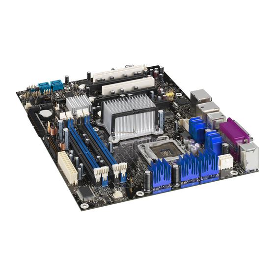
Desktop Board Components Figure 1 shows the approximate location of the major components on Desktop Board D975XBX. Figure 1. Desktop Board D975XBX Components IEEE 1394 Coaxial Digital Line Out G H I Channel A Channel B Desktop Board Features RJ45... -
Page 12: Desktop Board D975Xbx Components
Intel Desktop Board D975XBX Product Guide Table 2. Desktop Board D975XBX Components Label Description Auxiliary rear chassis fan header (4-pin) PCI bus add-in card connector 2 (SMBus routed) PCI Express x16 connector 3 (electrical x4) PCI bus add-in card connector 1... -
Page 13: Processor
The desktop board D975XBX supports an Intel not included with the desktop board and must be purchased separately. The processor connects to the Intel desktop board through the LGA775 socket. The supported processors list for Desktop Board D975XBX is located on the web at: http://support.intel.com/support/motherboards/desktop/... -
Page 14: Intel ® 975X Express Chipset
Go to the following link for more information about the Intel 975X Express Chipset: http://www.intel.com/products/desktop/chipsets Audio Subsystem The desktop board D975XBX includes a flexible 8-channel audio subsystem based on an Intel High Definition Audio codec: The audio subsystem features: •... -
Page 15: Input/Output (I/O) Controller
Support for RJ-45 connector with status indicator LEDs • Configurable EEPROM that contains the MAC address LAN Subsystem Software For LAN software and drivers, refer to the D975XBX link on Intel’s World Wide Web site at: http://support.intel.com/support/motherboards/desktop http://support.intel.com/support/motherboards/desktop/ Desktop Board Features... -
Page 16: Rj-45 Lan Connector Leds
Intel Desktop Board D975XBX Product Guide RJ-45 LAN Connector LEDs Two LEDs are built into the RJ-45 LAN connector located on the back panel (see Figure 2). Table 4 describes the LED states when the board is powered up and the 10/100/1000 Gigabit Ethernet LAN subsystem is operating. -
Page 17: Enhanced Ide Interface
Enhanced IDE Interface The ICH7 IDE interface handles the exchange of information between the processor and peripheral devices like hard disks, CD-ROM drives, and Iomega Zip* drives inside the computer. The interface supports: • Up to two IDE devices (such as hard drives) •... -
Page 18: Pci And Pci Express* Auto Configuration
Intel Desktop Board D975XBX Product Guide PCI and PCI Express* Auto Configuration If you install a PCI/PCI Express add-in card in your desktop board, the PCI/PCI Express auto- configuration utility in the BIOS automatically detects and configures the resources (IRQs, DMA channels, and I/O space) for that add-in card. -
Page 19: Acpi
The use of ACPI with the desktop board requires an operating system that provides full ACPI support. Fan Connectors Desktop Board D975XBX has three chassis fan connectors (two 3-pin and one 4-pin) and one processor fan connector (4-pin). ®... -
Page 20: Resume On Ring
Intel Desktop Board D975XBX Product Guide Figure 3. Location of Standby Power Indicator Related Links For more information on standby current requirements for the desktop board, go to the link below, select the desktop board name, and then select Technical Documentation: http://developer.intel.com/design/motherbd/... -
Page 21: Speaker
Speaker A speaker is mounted on the desktop board. The speaker provides audible error code (beep code) information during the Power-On Self-Test (POST). Battery A battery on the desktop board keeps the values in CMOS RAM and the clock current when the computer is turned off. - Page 22 Intel Desktop Board D975XBX Product Guide...
-
Page 23: Installing And Replacing Desktop Board Components
2 Installing and Replacing Desktop Board Components This chapter tells you how to: • Install the I/O shield • Install and remove the desktop board • Install and remove a processor • Install and remove memory • Install and remove a PCI Express x16 add-in card •... -
Page 24: Installation Precautions
Intel Desktop Board D975XBX Product Guide Installation Precautions When you install and test the Intel desktop board, observe all warnings and cautions in the installation instructions. To avoid injury, be careful of: • Sharp pins on connectors • Sharp pins on printed circuit assemblies •... -
Page 25: Installing The I/O Shield
Installing and Replacing Desktop Board Components Installing the I/O Shield The desktop board comes with an I/O shield. When installed in the chassis, the shield blocks radio frequency transmissions, protects internal components from dust and foreign objects, and promotes correct airflow within the chassis. Install the I/O shield before installing the desktop board in the chassis. -
Page 26: Installing And Removing The Desktop Board
Refer to Appendix B for regulatory requirements. Refer to your chassis manual for instructions on installing and removing the desktop board. Figure 5 shows the location of the 10 mounting screw holes for Desktop Board D975XBX. Figure 5. Location of Mounting Screw Holes... -
Page 27: Installing And Removing A Processor
Installing and Removing a Processor Instructions on how to install the processor on the desktop board are given below. Installing a Processor CAUTION Before installing or removing the processor, make sure that AC power has been removed by unplugging the power cord from the computer; the standby power LED should not be lit (see Figure 3 on page 20). -
Page 28: Remove The Protective Socket Cover
Intel Desktop Board D975XBX Product Guide 4. Remove the protective socket cover from the load plate. Do not discard the protective socket cover. Always replace the socket cover if the processor is removed from the socket (see Figure 8, E). -
Page 29: Install The Processor
6. Hold the processor with your thumb and index fingers oriented as shown in Figure 10. Make sure fingers align to the socket cutouts (see Figure 10, F). Align notches (see Figure 10, G) with the socket (see Figure 10, H). Lower the processor straight down without tilting or sliding it in the socket. -
Page 30: Installing The Processor Fan Heat Sink
For instructions on how to attach the processor fan heat sink to the integrated processor fan heat sink RM, refer to the boxed processor manual or the Intel World Wide Web site at: Integration of the Boxed Intel® Pentium® 4 Processor in the 775-Land Package Connecting the Processor Fan Heat Sink Cable Connect the processor fan heat sink cable to the 4-pin processor fan header (see Figure 12). -
Page 31: Installing And Removing Memory
Installing and Removing Memory Desktop Board D975XBX has four 240-pin DIMM sockets arranged as DIMM 0 and DIMM 1 in both Channel A and Channel B, as shown in Figure 17. Guidelines for Dual Channel Memory Configuration Before installing DIMMs, read and follow these guidelines for dual channel configuration. -
Page 32: Installing Dimms
Intel Desktop Board D975XBX Product Guide Three DIMMs Install a matched pair of DIMMs equal in speed and size in DIMM 0 (blue) and DIMM 1 (black) of channel A. Install a DIMM equal in speed and total size of the DIMMs installed in channel A in either DIMM 0 or DIMM 1 of channel B (see Figure 15). -
Page 33: Use Ddr2 Dimms
Installing and Replacing Desktop Board Components DDR2 OM18185 Figure 16. Use DDR2 DIMMs... -
Page 34: Installing A Dimm
Intel Desktop Board D975XBX Product Guide To install DIMMs, follow these steps: 1. Observe the precautions in "Before You Begin" on page 23. 2. Turn off all peripheral devices connected to the computer. Turn off the computer and disconnect the AC power cord. -
Page 35: Removing Dimms
Removing DIMMs To remove a memory module, follow these steps: 1. Observe the precautions in "Before You Begin" on page 23. 2. Turn off all peripheral devices connected to the computer. Turn off the computer. 3. Remove the AC power cord from the computer. 4. -
Page 36: Installing A Pci Express X16 Card
Intel Desktop Board D975XBX Product Guide Installing a PCI Express x16 Card If you are installing a single PCI Express Graphics card, install it in PCI Express connector 1 (see Figure 18, A) for optimum performance. However, if you are installing two PCI Express Graphics cards, install them in PCI Express connectors 1 and 2 (see Figure 18, B). -
Page 37: Removing The Pci Express X16 Card
Removing the PCI Express x16 Card Follow these instructions to remove the PCI Express x16 card from the RM: 1. Observe the precautions in "Before You Begin" on page 23. 2. Remove the screw that secures the card’s metal bracket to the chassis back panel (Figure 19, A). -
Page 38: Connecting The Ide Cable
Intel Desktop Board D975XBX Product Guide Connecting the IDE Cable The IDE cable can be used to connect two drives to the desktop board. The cable supports the ATA-66/100 transfer protocol. Figure 20 shows the correct installation of the cable. -
Page 39: Connecting The Serial Ata Cable
Installing and Replacing Desktop Board Components Connecting the Serial ATA Cable The SATA cable (4-conductor) supports the Serial ATA protocol and connects a single drive to the desktop board. Either end of the cable can be connected to the SATA drive or the connector on the board. -
Page 40: Connecting Internal Headers
Intel Desktop Board D975XBX Product Guide Connecting Internal Headers Before connecting cables to the internal headers, observe the precautions in "Before You Begin" on page 23. +5 V On/Off Reset Power HD LED Alternate Front Panel Power LED TPA1+ TPA1–... -
Page 41: Front Panel Audio Header
Front Panel Audio Header Figure 22, A on page 40 shows the location of the yellow front panel audio header. Table 5 shows the pin assignments for the front panel audio header. Table 5. Front Panel Audio Header Signal Names Signal Name Port1L Port1R... -
Page 42: Front Panel Header
Intel Desktop Board D975XBX Product Guide Front Panel Header Figure 22, E on page 40 shows the location of the multi-colored front panel header. Table 8 shows the pin assignments for the front panel header. Table 8. Front Panel Header Signal Names... -
Page 43: Installing The Rear Panel Usb 2.0 Adapter
Installing and Replacing Desktop Board Components Installing the Rear Panel USB 2.0 Adapter Follow these instructions to install the rear panel USB 2.0 adapter (see Figure 23): 1. Observe the precautions in "Before You Begin" on page 23. 2. Attach the cable end with the connector to the USB 2.0 header on the desktop board. 3. -
Page 44: Installing The Front Panel Usb/Ieee 1394/Audio Adapter
Intel Desktop Board D975XBX Product Guide Installing the Front Panel USB/IEEE 1394/Audio Adapter To install the front panel USB/IEEE 1394/audio adapter cables to the headers, follow these steps (see Figure 24): 1. Observe the precautions in "Before You Begin" on page 23. -
Page 45: Connecting Chassis Fan Cables
Installing and Replacing Desktop Board Components Connecting Chassis Fan Cables Connect the chassis fan cables to the desktop board fan headers shown in Figure 25. OM18194 Figure 25. Location of Fan Headers... -
Page 46: Connecting Power Supply Cables
Intel Desktop Board D975XBX Product Guide Connecting Power Supply Cables NOTE Failure to use the appropriate power supply and/or not connecting the 12 V (2x4) power connector to the desktop board may result in damage to the board or the system may not function properly. -
Page 47: Connecting 2X12 Power Supply Cables
2. Connect the 12 V processor core voltage power supply cable to the 2x4 connector. Use the 2x2 to 2x4 adapter if needed. NOTE Do not use the 2x2 to 2x4 adapter when using an Intel Pentium processor Extreme Edition or a ®... -
Page 48: Other Connectors
Use the 2x2 to 2x4 adapter if needed. NOTE Do not use the 2x2 to 2x4 adapter when using an Intel processor that is not running at its default settings. Doing so may result in damage to the desktop board. -
Page 49: Setting The Bios Configuration Jumper
Setting the BIOS Configuration Jumper CAUTION Always turn off the power and unplug the power cord from the computer before changing the jumper. Moving the jumper with the power on may result in unreliable computer operation. The location of the desktop board’s BIOS configuration jumper block is shown in Figure 29. Figure 29. -
Page 50: Clearing Passwords
Intel Desktop Board D975XBX Product Guide Clearing Passwords This procedure assumes that the board is installed in the computer and the configuration jumper block is set to normal mode. 1. Observe the precautions in "Before You Begin" on page 23. -
Page 51: Back Panel Connectors
Back Panel Connectors NOTE The line out connector, located on the back panel, is designed to power either headphones or amplified speakers only. Poor audio quality may occur if passive (non-amplified) speakers are connected to this output. Figure 30 shows the back panel connectors. Installing and Replacing Desktop Board Components RJ45 IEEE... -
Page 52: Replacing The Battery
Intel Desktop Board D975XBX Product Guide Replacing the Battery A coin-cell battery (CR2032) powers the real-time clock and CMOS memory. When the computer is not plugged into a wall socket, the battery has an estimated life of three years. When the computer is plugged in, the standby current from the power supply extends the life of the battery. - Page 53 Installing and Replacing Desktop Board Components AVVERTIMENTO Esiste il pericolo di un esplosione se la pila non viene sostituita in modo corretto. Utilizzare solo pile uguali o di tipo equivalente a quelle consigliate dal produttore. Per disfarsi delle pile usate, seguire le istruzioni del produttore.
- Page 54 Intel Desktop Board D975XBX Product Guide AWAS Risiko letupan wujud jika bateri digantikan dengan jenis yang tidak betul. Bateri sepatutnya dikitar semula jika boleh. Pelupusan bateri terpakai mestilah mematuhi peraturan alam sekitar tempatan. OSTRZEŻENIE Istnieje niebezpieczeństwo wybuchu w przypadku zastosowania niewłaściwego typu baterii. Zużyte baterie należy w miarę...
-
Page 55: Removing The Battery
UYARI Yanlış türde pil takıldığında patlama riski vardır. Piller mümkün olduğunda geri dönüştürülmelidir. Kullanılmış piller, yerel çevre yasalarına uygun olarak atılmalıdır. OСТОРОГА Використовуйте батареї правильного типу, інакше існуватиме ризик вибуху. Якщо можливо, використані батареї слід утилізувати. Утилізація використаних батарей має бути виконана згідно місцевих норм, що регулюють охорону довкілля. To replace the battery, follow these steps: 1. - Page 56 Intel Desktop Board D975XBX Product Guide...
-
Page 57: Bios
For the latest BIOS Setup menu options, go to the Intel World Wide Web site: http://support.intel.com/support/motherboards/desktop/ Updating the BIOS The BIOS can be updated by either using the Intel Express BIOS Update utility or the Iflash Memory Update utility. Updating the BIOS with the Intel With the Intel Express BIOS Update utility you can update the system BIOS while in the Windows environment. -
Page 58: Updating The Bios With The Iflash Memory Update Utility
You can obtain the BIOS update file through your computer supplier or by navigating to the Desktop Board D975XBX page on the Intel World Wide Web site at: http://support.intel.com/support/motherboards/desktop Navigate to the D975XBX page, click “[view] Latest BIOS updates,” and select the Iflash BIOS Update utility file. NOTE Review the instructions distributed with the update utility before attempting a BIOS update. - Page 59 Recovering the BIOS It is unlikely that anything will interrupt the BIOS update; however, if an interruption occurs, the BIOS could be damaged. The following steps explain how to recover the BIOS if an update fails. The following procedure uses recovery mode for the Setup program. See page 49 for more information on Setup modes.
- Page 60 Intel Desktop Board D975XBX Product Guide...
-
Page 61: Configuring For Raid
Press <Ctrl-I> to enter the RAID Configuration Utility. Press <Ctrl-I> and enter the RAID Configuration Utility. 2. In the Intel Matrix Storage Manager option ROM Main Menu, select option #1: Create RAID Volume. Enter a volume name and press <Enter>. -
Page 62: Setting Up A "Raid Ready" System
Serial ATA drive to RAID without reinstalling the operating system, when a second SATA hard drive is added to the system. Follow the steps described in the headings from this section: "Configuring the BIOS for Intel Matrix Storage Technology" and "Loading the Intel Matrix Storage Technology RAID Drivers and Software". -
Page 63: Intel ® Quick Resume Technology Driver (Intel ® Qrtd)
® platform and has the following features: • Instantly turns the Intel Viiv platform off by pressing the power button on the PC or remote control. • Instantly turns the Intel Viiv platform on by moving the mouse, pressing a key on the keyboard, or pressing the on/off button on the remote control or computer. - Page 64 When using the Microsoft* Windows* XP Media Center Edition remote control, the power button on the remote is controlled by the sleep button option on this properties page. If these options are not selected, the Intel Quick Resume Technology Driver off and on states cannot be accessed from the power button.
- Page 65 6. Verify the Return the computer from Away mode on mouse or keyboard activity is selected. If this is not selected, the Intel Viiv platform can only be turned on by pressing the power button on the PC or remote control. The keyboard, remote, and mouse will not turn the system on.
- Page 66 Intel Desktop Board D975XBX Product Guide...
-
Page 67: A Error Messages And Indicators
A Error Messages and Indicators Desktop Board D975XBX reports POST errors in two ways: • By sounding a beep code • By displaying an error message on the monitor BIOS Beep Codes The BIOS beep codes are listed in Table 10. The BIOS also issues a beep code (one long tone followed by two short tones) during POST if the video configuration fails (a faulty graphics card or no card installed) or if an external ROM module does not properly checksum to zero. - Page 68 Intel Desktop Board D975XBX Product Guide...
-
Page 69: B Regulatory Compliance
Product Ecology statements • Electromagnetic Compatibility (EMC) regulations • Product certifications Safety Regulations Desktop Board D975XBX complies with the safety regulations stated in Table 12 when correctly installed in a compatible host system. Table 12. Safety Regulations Regulation UL 60950-1:2003/ CSA C22.2 No. -
Page 70: European Union Declaration Of Conformity Statement
European Union Declaration of Conformity Statement We, Intel Corporation, declare under our sole responsibility that the product Intel D975XBX is in conformity with all applicable essential requirements necessary for CE marking, following the provisions of the European Council Directive 89/336/EEC (EMC Directive) and Council Directive 73/23/EEC (Safety/Low Voltage Directive). -
Page 71: Product Ecology Statements
Como parte de su compromiso de responsabilidad medioambiental, Intel ha implantado el programa de reciclaje de productos Intel, que permite que los consumidores al detalle de los productos Intel devuelvan los productos usados en los lugares seleccionados para su correspondiente reciclado. - Page 72 Intel Desktop Board D975XBX Product Guide Français Dans le cadre de son engagement pour la protection de l'environnement, Intel a mis en œuvre le programme Intel Product Recycling Program (Programme de recyclage des produits Intel) pour permettre aux consommateurs de produits Intel de recycler les produits usés en les retournant à des adresses spécifiées.
-
Page 73: Lead-Free Desktop Board
Türkçe Intel, çevre sorumluluğuna bağımlılığının bir parçası olarak, perakende tüketicilerin Intel markalı kullanılmış ürünlerini belirlenmiş merkezlere iade edip uygun şekilde geri dönüştürmesini amaçlayan Intel Ürünleri Geri Dönüşüm Programı’nı uygulamaya koymuştur. Bu programın ürün kapsamı, ürün iade merkezleri, nakliye talimatları, kayıtlar ve şartlar v.s dahil bütün ayrıntılarını... -
Page 74: Emc Regulations
Intel Desktop Board D975XBX Product Guide EMC Regulations Desktop Board D975XBX complies with the EMC regulations stated in Table 14 when correctly installed in a compatible host system. Table 14. EMC Regulations Regulation FCC Class B ICES-003 (Class B) EN55022: 1998... -
Page 75: Ensure Electromagnetic Compatibility (Emc) Compliance
Japanese Kanji statement translation: This is a Class B product based on the standard of the Voluntary Control Council for Interference from Information Technology Equipment (VCCI). If this is used near a radio or television receiver in a domestic environment, it may cause radio interference. -
Page 76: Product Certifications
Intel Desktop Board D975XBX Product Guide Product Certifications Board-Level Certification Markings Desktop Board D975XBX has the following product certification markings: Table 15. Product Certification Markings Description UL joint US/Canada Recognized Component mark. Includes adjacent UL file number for Intel desktop boards: E210882. -
Page 77: Chassis And Component Certifications
Regulatory Compliance Chassis and Component Certifications Ensure that the chassis and certain components; such as the power supply, peripheral drives, wiring, and cables; are components certified for the country or market where used. Agency certification marks on the product are proof of certification. Typical product certifications include: In Europe The CE marking signifies compliance with all applicable European requirements. - Page 78 Intel Desktop Board D975XBX Product Guide...