Table of Contents
Advertisement
Quick Links
Download this manual
See also:
Instruction Manual
Advertisement
Table of Contents

Related Manuals for Digimerge DPV24DL


Summary of Contents for Digimerge DPV24DL
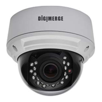
- Page 1 INSTRUCTION MANUAL Ultra Resolution Day & Night IR Dome Camera Ultra Resolution Vandal Model: DPV24DL Day & Night IR Dome Camera Indoor Model: DPD24DL P/N 01.BMS.11.0071401 Please read this manual thoroughly before use and keep it handy for future reference.
- Page 2 -ii-...
-
Page 3: Specifications
INTRODUCTION Features DPD24DL All Models Feature: • 1/3” Sony Super HAD™ II CCD • Indoor Dome Model • 2.8-10.5mm Varifocal Day/Night Lens F1.4 DC Iris • Camera Mounting: Surface / Flush mounting • 600 TV lines of resolution • Advanced Digital Noise Reduction (DNR) DPV24DL • Shadow Reduction (ATR) • Vandal Dome Model • Smart IR technology • Camera Mounting: Surface Mount • OSD menu control • Privacy Masking / Motion Detection • VIDEO OUT(BNC) • Operates in 12VDC or 24VAC • Test Monitor Output (RCA) • 0 Lux with IR LED SPECIFICATIONS... -
Page 4: Packing Contents
MEASUREMENTS PACKING CONTENTS 97.0 mm Indoor Dome package contains the following: 3.82 in Camera in housing ---------------------------------1 Camera Locking screw (PA3 Type) ------------1 55.5 mm Instruction guide (This Document) -------------1 2.19 in 3.4" Surface & Flush Mounting Templates----------2 Locking Conduit Star Shape 87 mm Screw... -
Page 5: Junction Box Installation Types
JUNCTION BOX INSTALLATION TYPES VANDAL DOME FITTINGS a. 2S Fitting requires only 2pcs of base Screws attachment screws. Note: You have a reduced space in which to hide cables using this type of installation. Recommended for indoor dome only. Cable Entry Pendant Cap - model # MNTV2XPC Note: All plate fittings are put so screw holes... -
Page 6: Installation. Vandal Dome
INSTALLATION. VANDAL DOME INSTALLATION. INTERNAL DOME a) Remove the three tamper screws using the Hex key provided. a) Press down on the tab marked with an arrow to lift up the dome cover slightly b) Use included mounting template to mark and pre-drill the required holes. -
Page 7: Camera Adjustment
CAMERA ADJUSTMENT CAMERA ADJUSTMENT MANUAL WB USER1 WB SPEED LEVEL B-GAIN DELAY CNT R-GAIN RCA Service Connector ATW FRAME x1.00 ENVIRONMENT OUTDOOR Use supplied RCA - BNC cable OSD function joystick. Pressing down If you require BNC output. on joystick acts as ENTER function. MENU TREE SUMMARY RETURN ... -
Page 8: Setup Menu
CAMERA ADJUSTMENT CAMERA ADJUSTMENT OSD MENU control Select the language in which to display the OSD menu. Note: Selection changes the language displayed immediatley. Press down on the function joystick to access the setup menu. LANGUAGE: English,Japanese,German, French • Main setup menu is displayed on the monitor screen. Russian, Portuguese, Spanish, Chinese. -
Page 9: White Bal
CAMERA ADJUSTMENT CAMERA ADJUSTMENT WHITE BAL USER1 WB SETUP MENU B-GAIN LANGUAGE ENGLISH R-GAIN LENS AUTO WHITE BAL ATW PICT ADJUST White Balance can be set to following: RETURN NEXT EXIT SAVE ALL ATW / PUSH / USER1 / USER2 / ANTI CR / MANUAL / PUSH LOCK • ... -
Page 10: Pict Adjust
CAMERA ADJUSTMENT CAMERA ADJUSTMENT LEVEL: 000-255 Specifies the R and B gain values for manual WB. The actual variable range is limited to the range from the low color temperature SETUP MENU (approx. 1800K) to the high color temperature (approx. 10500K). LANGUAGE ENGLISH LENS... - Page 11 CAMERA ADJUSTMENT CAMERA ADJUSTMENT •LUMINANCE Sets the extent of the luminance compression (MID/HIGH/LOW) SETUP MENU •CONTRAST Sets the extent of the contrast enhancement BACKLIGHT (MID/MIDHIGH/HIGH/LOW/MIDLOW) PRIVACY MOTION DET PRIVACY OFF / ON CAMERA ID Hide an area so that it is not displayed on the monitor. SYNC CAMERA RESET PRIVACY...
-
Page 12: Motion Det
CAMERA ADJUSTMENT CAMERA ADJUSTMENT MOTION DET OFF / ON BOTTOM: Set the bottom side of the monitoring frame selected by the AREA SEL parameter Motion Detection is defined by rectangular areas. This give a visual identification LEFT: Set the left side of the monitoring frame selected by the AREA SEL of motion areas. -
Page 13: Troubleshooting
CAMERA ADJUSTMENT TROUBLE SHOOTING Refer to the following table if you are experiencing trouble with your camera. Contact an authorized technician if the table does not provide you with a solution to the trouble. PHASE Nothing appears on the screen. Check that the power cord and line connection between the camera and monitor are connected properly.